EP0303956A2 - Hachoir à viande - Google Patents
Hachoir à viande Download PDFInfo
- Publication number
- EP0303956A2 EP0303956A2 EP88112983A EP88112983A EP0303956A2 EP 0303956 A2 EP0303956 A2 EP 0303956A2 EP 88112983 A EP88112983 A EP 88112983A EP 88112983 A EP88112983 A EP 88112983A EP 0303956 A2 EP0303956 A2 EP 0303956A2
- Authority
- EP
- European Patent Office
- Prior art keywords
- locking
- housing
- segment
- conveyor housing
- conveyor
- Prior art date
- Legal status (The legal status is an assumption and is not a legal conclusion. Google has not performed a legal analysis and makes no representation as to the accuracy of the status listed.)
- Granted
Links
Images


Classifications
-
- B—PERFORMING OPERATIONS; TRANSPORTING
- B02—CRUSHING, PULVERISING, OR DISINTEGRATING; PREPARATORY TREATMENT OF GRAIN FOR MILLING
- B02C—CRUSHING, PULVERISING, OR DISINTEGRATING IN GENERAL; MILLING GRAIN
- B02C18/00—Disintegrating by knives or other cutting or tearing members which chop material into fragments
- B02C18/30—Mincing machines with perforated discs and feeding worms
- B02C18/305—Details
-
- B—PERFORMING OPERATIONS; TRANSPORTING
- B02—CRUSHING, PULVERISING, OR DISINTEGRATING; PREPARATORY TREATMENT OF GRAIN FOR MILLING
- B02C—CRUSHING, PULVERISING, OR DISINTEGRATING IN GENERAL; MILLING GRAIN
- B02C18/00—Disintegrating by knives or other cutting or tearing members which chop material into fragments
- B02C18/30—Mincing machines with perforated discs and feeding worms
- B02C18/301—Mincing machines with perforated discs and feeding worms with horizontal axis
- B02C18/302—Mincing machines with perforated discs and feeding worms with horizontal axis with a knife-perforated disc unit
Definitions
- the invention relates to a meat grinder with a housing, a drive unit consisting of a motor and gearbox, a rotary switch for switching the motor on and off, a receptacle bushing that is firmly connected to the gearbox and has a filler shaft, a feed housing that can be inserted into the receptacle bushing in the conveyor housing rotatable screw conveyor, which is connected at one end to the gearbox by a plug-in coupling, a cutting set associated with the conveyor housing and the screw conveyor and a locking device that can be engaged and disengaged for precisely fixing the conveyor housing in the receiving bushing.
- the locking device comprises a locking shaft which can be moved back and forth between an engaging and a disengaging position and which allows the motor to be switched on only in the engaging position and when the conveyor housing is fixed in position in the receiving bushing.
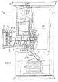
- the meat grinder 1 shown schematically in FIG. 1 essentially consists of a machine housing 2 with a filling bowl 3 releasably connected thereto, to which a filling shaft 4 is fastened.
- the feed chute 4 merges into a receiving bushing 5, which serves for the storage of a delivery housing 6.
- a screw conveyor 7 is rotatably arranged in the conveyor housing 6, a screw conveyor 7 is rotatably arranged.
- the screw conveyor 7 is driven by a drive motor 13 (shown in broken lines), a belt drive 14 and a gear 15, the gear 15 being fixedly connected to the receiving bush 5.
- the screw conveyor is driven by a plug-in coupling. This consists of a square shoulder 16 of the worm 7, which penetrates into a corresponding recess in a drive shaft 17 of the gear 15 designed as a hollow shaft.
- the conveyor housing 6 rests against a stop collar 18 of the receiving bush 5.
- the screw conveyor 7 has at its drive end a collar 19 which is arranged at a safety distance S with respect to a rear wall 20 of the conveyor housing 6.
- the conveyor housing 6 is locked in the receiving bush 5 while maintaining the safety distance S by means of a locking shaft 21 which can be pivoted back and forth between an engagement and disengagement position via a lever 22 rigidly connected to it.
- the axis of rotation of the locking shaft 21 is perpendicular to the longitudinal axis of the receiving bush 5 and the conveyor housing 6, so that the shaft 21 tangentially cuts the at least partially circular-cylindrical components 5 and 6.
- the wall of the receiving bushing 5 and the conveying housing 6 each have tangential "half-bores" 45 and 24, which enclose the circular-cylindrical locking shaft 21.
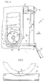
- This in turn has - compare FIGS. 2 and 3 - a recess 23 in the area of these half-bores, which in the engaged position of the locking shaft 21 fixes the conveyor housing 6 in the receiving bush 5, depending on the disengaged position against insertion or extraction of the conveyor housing 6 with respect to the receiving bush 5.
- the recess 23 is adapted to the shape of the outer circumference of the conveyor housing 6 accordingly.
- the locking shaft 21 can be moved back and forth by the lever 22 between the engagement and disengagement position.
- a first locking segment 25 is connected in a rotationally fixed manner to the locking shaft 21.
- a conventional rotary switch 27 arranged on the machine housing 2 for switching the electric motor 13 on and off has a switching shaft 26 with a switching handle 29 arranged thereon.
- a second locking segment 28 is connected in a rotationally fixed manner to the switching shaft 26 and has a guide surface 30 curved concavely about the axis of rotation of the locking shaft 21 and an elongated leg 31.
- Two bolts 32 protrude from the first locking segment 25 towards the second locking segment 28 and are in abutment against the guide surface 30 in the disengaged position of the locking shaft 21.
- the bolts 32 act as stops and prevent the second blocking segment 28 and the rotary switch 27 from rotating, so that the motor 13 of the meat grinder 1 cannot be switched on. Only when the shaft 21 is pivoted into the engaged position and thereby the conveyor housing 6 is locked in the receiving bush 5 (shown in broken lines in FIG. 4) can the second locking segment and with it the rotary switch 27 be brought into the switched-on position (also shown in broken lines in FIG. 4) shown).
- the arrangement of the bolts 32 and the guide surface 30 is designed so that when the first locking segment 25 is pivoted back out of the moved into the engaged position, the second locking segment 28 and thus the rotary switch 27 are taken automatically and thereby the meat grinder 1 is switched off.
- the locking device according to FIGS. 1 to 4 thus provides double security in that it becomes effective both when the motor 13 is switched on and when the lock is released.
- the receiving bushing 5 and the conveying housing 6 are locked together by a displaceable bolt 34 which is prestressed by a spring 33, the bolt 34 being guided in the receiving bushing 5 and being able to penetrate into a corresponding recess 35 in the conveying housing 6.
- an eccentric disk 36 is arranged, by means of which the bolt 34 can be engaged and disengaged by pivoting the shaft 21.
- the embodiment according to FIG. 5 corresponds to the embodiment according to FIGS. 1 to 4.
- the locking shaft is designed as a screw spindle 38 which can be rotated in a screw thread of the receiving bushing 5 and can thus be moved axially back and forth with respect to this bushing.
- a rotary handle 37 is seated on one end of the screw spindle 38, the other end of the screw spindle is designed as a fixing pin 39 which, when the spindle 38 is rotated, penetrates into a corresponding recess 40 in the feed housing 6 and locks it with the receiving bush 5.
- the screw spindle 38 is seated and the selector shaft 26 each rotatably locking segments 41 and 42, the shape of which is best seen in Figure 7.
- the locking segment 41 (see FIG. 6) is axially displaced with respect to the locking segment 42, so that the locking segment 42 and thus the rotary switch 27 can be actuated without hindrance.
- the fixing pin 39 is not in engagement with the recess 40 and therefore the conveyor housing 6 is not locked with the receiving bush 5, the first locking segment 41 engages in a corresponding recess 44 in the second locking segment, so that it is blocked and the Rotary switch 27 can not be turned on (dash-dotted lines in Figure 7).
- FIGS. 6 and 7 is simplified compared to the embodiments according to FIGS. 1 to 5, because when the screw spindle 38 is moved from the engaged to the disengaged position, there is no inevitable return of the rotary switch 27 from the switch-on to the switch-off position.
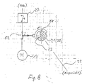
- FIG. 8 schematically shows a further embodiment of the invention.
- a switch cam 51 which interrupts the electrical current flow from the mains via a safety limit switch 52 and via the switch 27 to the motor 13 if the shaft 21 is not in the engagement position and the conveyor housing 6 is not fixed in position in the receiving socket 5 is. Switching on the motor 13 is therefore only possible with the conveyor housing 6 properly fixed.
- switch 27 can also in this embodiment a self-holding circuit with a switch protection can be used in a manner known per se.
Landscapes
- Engineering & Computer Science (AREA)
- Food Science & Technology (AREA)
- Crushing And Pulverization Processes (AREA)
- Meat, Egg Or Seafood Products (AREA)
Priority Applications (1)
| Application Number | Priority Date | Filing Date | Title |
|---|---|---|---|
| AT88112983T ATE96056T1 (de) | 1987-08-20 | 1988-08-10 | Fleischwolf. |
Applications Claiming Priority (2)
| Application Number | Priority Date | Filing Date | Title |
|---|---|---|---|
| DE19873727751 DE3727751A1 (de) | 1987-08-20 | 1987-08-20 | Fleischwolf |
| DE3727751 | 1987-08-20 |
Publications (3)
| Publication Number | Publication Date |
|---|---|
| EP0303956A2 true EP0303956A2 (fr) | 1989-02-22 |
| EP0303956A3 EP0303956A3 (en) | 1990-01-17 |
| EP0303956B1 EP0303956B1 (fr) | 1993-10-20 |
Family
ID=6334113
Family Applications (1)
| Application Number | Title | Priority Date | Filing Date |
|---|---|---|---|
| EP88112983A Expired - Lifetime EP0303956B1 (fr) | 1987-08-20 | 1988-08-10 | Hachoir à viande |
Country Status (3)
| Country | Link |
|---|---|
| EP (1) | EP0303956B1 (fr) |
| AT (1) | ATE96056T1 (fr) |
| DE (2) | DE3727751A1 (fr) |
Cited By (4)
| Publication number | Priority date | Publication date | Assignee | Title |
|---|---|---|---|---|
| EP0695581A1 (fr) * | 1994-08-04 | 1996-02-07 | Braun Aktiengesellschaft | Hachoir à viande |
| EP1832346A3 (fr) * | 2006-03-07 | 2009-03-11 | La Minerva Di Chiodini Mario S.R.L. | Dispositif de sécurité pour hachoir à viande et similaires |
| ITVI20100352A1 (it) * | 2010-12-28 | 2012-06-29 | Felsinea S R L | Dispositivo automatizzato di sicurezza per tritacarne |
| ITBO20110463A1 (it) * | 2011-07-29 | 2013-01-30 | Essedue S R L | Dispositivo di sicurezza per tritacarne o simili. |
Family Cites Families (6)
| Publication number | Priority date | Publication date | Assignee | Title |
|---|---|---|---|---|
| DE450116C (de) * | 1926-11-13 | 1927-09-29 | Wommer Maschinenfabrik Geb | Ein-, Ausschalt- und Ausstossvorrichtung bei Fleischwoelfen |
| DE923952C (de) * | 1953-03-08 | 1955-02-24 | Krauss Maffei Ag | Fleischwolf mit Drehstromantrieb |
| DE8320586U1 (de) * | 1983-07-16 | 1983-12-22 | Samix-Umwelttechnik-Maschinenbau GmbH, 6330 Kufstein | Vorrichtung zum zerkleinern von haeckselgut |
| DE3503718A1 (de) * | 1985-02-04 | 1985-07-25 | Bosch-Siemens Hausgeräte GmbH, 7000 Stuttgart | Elektrische kuechenmaschine |
| DE8526418U1 (de) * | 1985-09-16 | 1986-02-13 | Robert Stahlschmidt RST Motorenwerk GmbH, 4800 Bielefeld | Gerät mit umlaufendem Werkzeug |
| DE8526857U1 (de) * | 1985-09-19 | 1985-10-31 | Atika-Maschinenfabrik Wilhelm Pollmeier GmbH & Co, 4730 Ahlen | Gartenhäcksler |
-
1987
- 1987-08-20 DE DE19873727751 patent/DE3727751A1/de not_active Withdrawn
-
1988
- 1988-08-10 EP EP88112983A patent/EP0303956B1/fr not_active Expired - Lifetime
- 1988-08-10 DE DE88112983T patent/DE3885039D1/de not_active Expired - Fee Related
- 1988-08-10 AT AT88112983T patent/ATE96056T1/de not_active IP Right Cessation
Cited By (5)
| Publication number | Priority date | Publication date | Assignee | Title |
|---|---|---|---|---|
| EP0695581A1 (fr) * | 1994-08-04 | 1996-02-07 | Braun Aktiengesellschaft | Hachoir à viande |
| EP1832346A3 (fr) * | 2006-03-07 | 2009-03-11 | La Minerva Di Chiodini Mario S.R.L. | Dispositif de sécurité pour hachoir à viande et similaires |
| ITVI20100352A1 (it) * | 2010-12-28 | 2012-06-29 | Felsinea S R L | Dispositivo automatizzato di sicurezza per tritacarne |
| EP2471601A1 (fr) * | 2010-12-28 | 2012-07-04 | La Felsinea S.r.L. | Dispositif de sécurité automatisé pour hachoirs |
| ITBO20110463A1 (it) * | 2011-07-29 | 2013-01-30 | Essedue S R L | Dispositivo di sicurezza per tritacarne o simili. |
Also Published As
| Publication number | Publication date |
|---|---|
| ATE96056T1 (de) | 1993-11-15 |
| EP0303956B1 (fr) | 1993-10-20 |
| EP0303956A3 (en) | 1990-01-17 |
| DE3885039D1 (de) | 1993-11-25 |
| DE3727751A1 (de) | 1989-03-02 |
Similar Documents
| Publication | Publication Date | Title |
|---|---|---|
| DE69409134T2 (de) | Halterungssystem für ein Sägeblatt | |
| EP0650805B1 (fr) | Outil électrique | |
| EP0401548B1 (fr) | Dispositif à outil de vissage | |
| DE3741484C1 (de) | Handwerkzeugmaschine mit automatischer Arretierung der Arbeitsspindel | |
| EP0023951B1 (fr) | Outil à main entraîné par un moteur, en particulier outil à usages multiples pour bricoleurs | |
| DE2613065C3 (de) | Automatische Kupplungsvorrichtung für ein Handrad | |
| EP0716896A1 (fr) | Dispositif de perçage | |
| EP1092379B1 (fr) | Mixeur à main électrique | |
| DE69218823T2 (de) | Lageeinstell- und Begrenzungsvorrichtung für ein zentrifugales Betätigungselement eines Elektromotors | |
| EP1572403B1 (fr) | Mandrin de serrage et tige de serrage destinee a celui-ci | |
| DE102014116705B4 (de) | Laborrührer | |
| DE2904535C2 (de) | Drehantrieb für eine Schneidvorrichtung zum Zerkleinern von Nahrungsmitteln | |
| EP0303956B1 (fr) | Hachoir à viande | |
| DE3305632C2 (de) | Reibungskupplungs- und Bremskombination | |
| EP0237857B1 (fr) | Dispositif d'entraînement pour un sectionneur électrique | |
| EP0054912B1 (fr) | Dispositif, en particulier dispositif portatif, pour l'usinage de pièces en forme de tubes et/ou de barres et analogues | |
| DE29502032U1 (de) | Preßwerkzeug | |
| DE2755401A1 (de) | Anordnung zum absenken der leerlaufdrehzahl eines elektromotors | |
| EP0095572A1 (fr) | Dispositif de blocage du sens de rotation du rotor d'un moteur synchrone | |
| DE102016015728B4 (de) | Parksperren-Aktuatoreinheit | |
| DE4208474C2 (de) | Handrad-Stellvorrichtung für Offset-Druckmaschinen | |
| DE1654887C3 (de) | Werkzeug-Auswerfvorrichtung für eine elektrische Küchenmaschine, insbesondere einen Handquirl | |
| DE1009886B (de) | Handrad fuer die Feinverstellung der Schlitten von Werkzeugmaschinen, insbesondere Fraesmaschinen | |
| EP4480650B1 (fr) | Coupe-bordures, ensemble d'accouplement associé et utilisation associée | |
| DE3347968C2 (de) | Zigaretten-Stopfgerät |
Legal Events
| Date | Code | Title | Description |
|---|---|---|---|
| PUAI | Public reference made under article 153(3) epc to a published international application that has entered the european phase |
Free format text: ORIGINAL CODE: 0009012 |
|
| AK | Designated contracting states |
Kind code of ref document: A2 Designated state(s): AT DE FR GB |
|
| PUAL | Search report despatched |
Free format text: ORIGINAL CODE: 0009013 |
|
| AK | Designated contracting states |
Kind code of ref document: A3 Designated state(s): AT DE FR GB |
|
| 17P | Request for examination filed |
Effective date: 19900628 |
|
| 17Q | First examination report despatched |
Effective date: 19910822 |
|
| GRAA | (expected) grant |
Free format text: ORIGINAL CODE: 0009210 |
|
| AK | Designated contracting states |
Kind code of ref document: B1 Designated state(s): AT DE FR GB |
|
| REF | Corresponds to: |
Ref document number: 96056 Country of ref document: AT Date of ref document: 19931115 Kind code of ref document: T |
|
| REF | Corresponds to: |
Ref document number: 3885039 Country of ref document: DE Date of ref document: 19931125 |
|
| GBT | Gb: translation of ep patent filed (gb section 77(6)(a)/1977) |
Effective date: 19931109 |
|
| ET | Fr: translation filed | ||
| PLBE | No opposition filed within time limit |
Free format text: ORIGINAL CODE: 0009261 |
|
| STAA | Information on the status of an ep patent application or granted ep patent |
Free format text: STATUS: NO OPPOSITION FILED WITHIN TIME LIMIT |
|
| 26N | No opposition filed | ||
| PGFP | Annual fee paid to national office [announced via postgrant information from national office to epo] |
Ref country code: FR Payment date: 20010801 Year of fee payment: 14 |
|
| PGFP | Annual fee paid to national office [announced via postgrant information from national office to epo] |
Ref country code: GB Payment date: 20010810 Year of fee payment: 14 |
|
| PGFP | Annual fee paid to national office [announced via postgrant information from national office to epo] |
Ref country code: AT Payment date: 20010818 Year of fee payment: 14 |
|
| PGFP | Annual fee paid to national office [announced via postgrant information from national office to epo] |
Ref country code: DE Payment date: 20010924 Year of fee payment: 14 |
|
| REG | Reference to a national code |
Ref country code: GB Ref legal event code: IF02 |
|
| PG25 | Lapsed in a contracting state [announced via postgrant information from national office to epo] |
Ref country code: GB Free format text: LAPSE BECAUSE OF NON-PAYMENT OF DUE FEES Effective date: 20020810 Ref country code: AT Free format text: LAPSE BECAUSE OF NON-PAYMENT OF DUE FEES Effective date: 20020810 |
|
| PG25 | Lapsed in a contracting state [announced via postgrant information from national office to epo] |
Ref country code: DE Free format text: LAPSE BECAUSE OF NON-PAYMENT OF DUE FEES Effective date: 20030301 |
|
| GBPC | Gb: european patent ceased through non-payment of renewal fee |
Effective date: 20020810 |
|
| PG25 | Lapsed in a contracting state [announced via postgrant information from national office to epo] |
Ref country code: FR Free format text: LAPSE BECAUSE OF NON-PAYMENT OF DUE FEES Effective date: 20030430 |
|
| REG | Reference to a national code |
Ref country code: FR Ref legal event code: ST |