EP0304061A2 - Länglicher Formkörper aus supraleitender Keramik und Verfahren zu seiner Herstellung - Google Patents
Länglicher Formkörper aus supraleitender Keramik und Verfahren zu seiner Herstellung Download PDFInfo
- Publication number
- EP0304061A2 EP0304061A2 EP88113445A EP88113445A EP0304061A2 EP 0304061 A2 EP0304061 A2 EP 0304061A2 EP 88113445 A EP88113445 A EP 88113445A EP 88113445 A EP88113445 A EP 88113445A EP 0304061 A2 EP0304061 A2 EP 0304061A2
- Authority
- EP
- European Patent Office
- Prior art keywords
- superconducting
- ceramics
- ceramics elongated
- elongated body
- elongated substrate
- Prior art date
- Legal status (The legal status is an assumption and is not a legal conclusion. Google has not performed a legal analysis and makes no representation as to the accuracy of the status listed.)
- Granted
Links
Images



Classifications
-
- C—CHEMISTRY; METALLURGY
- C04—CEMENTS; CONCRETE; ARTIFICIAL STONE; CERAMICS; REFRACTORIES
- C04B—LIME, MAGNESIA; SLAG; CEMENTS; COMPOSITIONS THEREOF, e.g. MORTARS, CONCRETE OR LIKE BUILDING MATERIALS; ARTIFICIAL STONE; CERAMICS; REFRACTORIES; TREATMENT OF NATURAL STONE
- C04B35/00—Shaped ceramic products characterised by their composition; Ceramics compositions; Processing powders of inorganic compounds preparatory to the manufacturing of ceramic products
- C04B35/622—Forming processes; Processing powders of inorganic compounds preparatory to the manufacturing of ceramic products
- C04B35/62222—Forming processes; Processing powders of inorganic compounds preparatory to the manufacturing of ceramic products obtaining ceramic coatings
-
- C—CHEMISTRY; METALLURGY
- C01—INORGANIC CHEMISTRY
- C01G—COMPOUNDS CONTAINING METALS NOT COVERED BY SUBCLASSES C01D OR C01F
- C01G3/00—Compounds of copper
- C01G3/006—Compounds containing copper, with or without oxygen or hydrogen, and containing two or more other elements
-
- C—CHEMISTRY; METALLURGY
- C04—CEMENTS; CONCRETE; ARTIFICIAL STONE; CERAMICS; REFRACTORIES
- C04B—LIME, MAGNESIA; SLAG; CEMENTS; COMPOSITIONS THEREOF, e.g. MORTARS, CONCRETE OR LIKE BUILDING MATERIALS; ARTIFICIAL STONE; CERAMICS; REFRACTORIES; TREATMENT OF NATURAL STONE
- C04B35/00—Shaped ceramic products characterised by their composition; Ceramics compositions; Processing powders of inorganic compounds preparatory to the manufacturing of ceramic products
- C04B35/01—Shaped ceramic products characterised by their composition; Ceramics compositions; Processing powders of inorganic compounds preparatory to the manufacturing of ceramic products based on oxide ceramics
- C04B35/45—Shaped ceramic products characterised by their composition; Ceramics compositions; Processing powders of inorganic compounds preparatory to the manufacturing of ceramic products based on oxide ceramics based on copper oxide or solid solutions thereof with other oxides
-
- C—CHEMISTRY; METALLURGY
- C04—CEMENTS; CONCRETE; ARTIFICIAL STONE; CERAMICS; REFRACTORIES
- C04B—LIME, MAGNESIA; SLAG; CEMENTS; COMPOSITIONS THEREOF, e.g. MORTARS, CONCRETE OR LIKE BUILDING MATERIALS; ARTIFICIAL STONE; CERAMICS; REFRACTORIES; TREATMENT OF NATURAL STONE
- C04B35/00—Shaped ceramic products characterised by their composition; Ceramics compositions; Processing powders of inorganic compounds preparatory to the manufacturing of ceramic products
- C04B35/01—Shaped ceramic products characterised by their composition; Ceramics compositions; Processing powders of inorganic compounds preparatory to the manufacturing of ceramic products based on oxide ceramics
- C04B35/45—Shaped ceramic products characterised by their composition; Ceramics compositions; Processing powders of inorganic compounds preparatory to the manufacturing of ceramic products based on oxide ceramics based on copper oxide or solid solutions thereof with other oxides
- C04B35/4504—Shaped ceramic products characterised by their composition; Ceramics compositions; Processing powders of inorganic compounds preparatory to the manufacturing of ceramic products based on oxide ceramics based on copper oxide or solid solutions thereof with other oxides containing rare earth oxides
-
- C—CHEMISTRY; METALLURGY
- C04—CEMENTS; CONCRETE; ARTIFICIAL STONE; CERAMICS; REFRACTORIES
- C04B—LIME, MAGNESIA; SLAG; CEMENTS; COMPOSITIONS THEREOF, e.g. MORTARS, CONCRETE OR LIKE BUILDING MATERIALS; ARTIFICIAL STONE; CERAMICS; REFRACTORIES; TREATMENT OF NATURAL STONE
- C04B35/00—Shaped ceramic products characterised by their composition; Ceramics compositions; Processing powders of inorganic compounds preparatory to the manufacturing of ceramic products
- C04B35/01—Shaped ceramic products characterised by their composition; Ceramics compositions; Processing powders of inorganic compounds preparatory to the manufacturing of ceramic products based on oxide ceramics
- C04B35/45—Shaped ceramic products characterised by their composition; Ceramics compositions; Processing powders of inorganic compounds preparatory to the manufacturing of ceramic products based on oxide ceramics based on copper oxide or solid solutions thereof with other oxides
- C04B35/4504—Shaped ceramic products characterised by their composition; Ceramics compositions; Processing powders of inorganic compounds preparatory to the manufacturing of ceramic products based on oxide ceramics based on copper oxide or solid solutions thereof with other oxides containing rare earth oxides
- C04B35/4508—Type 1-2-3
-
- C—CHEMISTRY; METALLURGY
- C04—CEMENTS; CONCRETE; ARTIFICIAL STONE; CERAMICS; REFRACTORIES
- C04B—LIME, MAGNESIA; SLAG; CEMENTS; COMPOSITIONS THEREOF, e.g. MORTARS, CONCRETE OR LIKE BUILDING MATERIALS; ARTIFICIAL STONE; CERAMICS; REFRACTORIES; TREATMENT OF NATURAL STONE
- C04B41/00—After-treatment of mortars, concrete, artificial stone or ceramics; Treatment of natural stone
- C04B41/009—After-treatment of mortars, concrete, artificial stone or ceramics; Treatment of natural stone characterised by the material treated
-
- C—CHEMISTRY; METALLURGY
- C04—CEMENTS; CONCRETE; ARTIFICIAL STONE; CERAMICS; REFRACTORIES
- C04B—LIME, MAGNESIA; SLAG; CEMENTS; COMPOSITIONS THEREOF, e.g. MORTARS, CONCRETE OR LIKE BUILDING MATERIALS; ARTIFICIAL STONE; CERAMICS; REFRACTORIES; TREATMENT OF NATURAL STONE
- C04B41/00—After-treatment of mortars, concrete, artificial stone or ceramics; Treatment of natural stone
- C04B41/45—Coating or impregnating, e.g. injection in masonry, partial coating of green or fired ceramics, organic coating compositions for adhering together two concrete elements
- C04B41/50—Coating or impregnating, e.g. injection in masonry, partial coating of green or fired ceramics, organic coating compositions for adhering together two concrete elements with inorganic materials
- C04B41/5072—Coating or impregnating, e.g. injection in masonry, partial coating of green or fired ceramics, organic coating compositions for adhering together two concrete elements with inorganic materials with oxides or hydroxides not covered by C04B41/5025
- C04B41/5074—Copper oxide or solid solutions thereof
-
- C—CHEMISTRY; METALLURGY
- C04—CEMENTS; CONCRETE; ARTIFICIAL STONE; CERAMICS; REFRACTORIES
- C04B—LIME, MAGNESIA; SLAG; CEMENTS; COMPOSITIONS THEREOF, e.g. MORTARS, CONCRETE OR LIKE BUILDING MATERIALS; ARTIFICIAL STONE; CERAMICS; REFRACTORIES; TREATMENT OF NATURAL STONE
- C04B41/00—After-treatment of mortars, concrete, artificial stone or ceramics; Treatment of natural stone
- C04B41/45—Coating or impregnating, e.g. injection in masonry, partial coating of green or fired ceramics, organic coating compositions for adhering together two concrete elements
- C04B41/52—Multiple coating or impregnating multiple coating or impregnating with the same composition or with compositions only differing in the concentration of the constituents, is classified as single coating or impregnation
-
- C—CHEMISTRY; METALLURGY
- C04—CEMENTS; CONCRETE; ARTIFICIAL STONE; CERAMICS; REFRACTORIES
- C04B—LIME, MAGNESIA; SLAG; CEMENTS; COMPOSITIONS THEREOF, e.g. MORTARS, CONCRETE OR LIKE BUILDING MATERIALS; ARTIFICIAL STONE; CERAMICS; REFRACTORIES; TREATMENT OF NATURAL STONE
- C04B41/00—After-treatment of mortars, concrete, artificial stone or ceramics; Treatment of natural stone
- C04B41/80—After-treatment of mortars, concrete, artificial stone or ceramics; Treatment of natural stone of only ceramics
- C04B41/81—Coating or impregnation
- C04B41/85—Coating or impregnation with inorganic materials
-
- C—CHEMISTRY; METALLURGY
- C04—CEMENTS; CONCRETE; ARTIFICIAL STONE; CERAMICS; REFRACTORIES
- C04B—LIME, MAGNESIA; SLAG; CEMENTS; COMPOSITIONS THEREOF, e.g. MORTARS, CONCRETE OR LIKE BUILDING MATERIALS; ARTIFICIAL STONE; CERAMICS; REFRACTORIES; TREATMENT OF NATURAL STONE
- C04B41/00—After-treatment of mortars, concrete, artificial stone or ceramics; Treatment of natural stone
- C04B41/80—After-treatment of mortars, concrete, artificial stone or ceramics; Treatment of natural stone of only ceramics
- C04B41/81—Coating or impregnation
- C04B41/89—Coating or impregnation for obtaining at least two superposed coatings having different compositions
-
- H—ELECTRICITY
- H10—SEMICONDUCTOR DEVICES; ELECTRIC SOLID-STATE DEVICES NOT OTHERWISE PROVIDED FOR
- H10N—ELECTRIC SOLID-STATE DEVICES NOT OTHERWISE PROVIDED FOR
- H10N60/00—Superconducting devices
- H10N60/01—Manufacture or treatment
- H10N60/0268—Manufacture or treatment of devices comprising copper oxide
- H10N60/0296—Processes for depositing or forming copper oxide superconductor layers
- H10N60/0324—Processes for depositing or forming copper oxide superconductor layers from a solution
-
- H—ELECTRICITY
- H10—SEMICONDUCTOR DEVICES; ELECTRIC SOLID-STATE DEVICES NOT OTHERWISE PROVIDED FOR
- H10N—ELECTRIC SOLID-STATE DEVICES NOT OTHERWISE PROVIDED FOR
- H10N60/00—Superconducting devices
- H10N60/01—Manufacture or treatment
- H10N60/0268—Manufacture or treatment of devices comprising copper oxide
- H10N60/0296—Processes for depositing or forming copper oxide superconductor layers
- H10N60/0381—Processes for depositing or forming copper oxide superconductor layers by evaporation, e.g. MBE
-
- H—ELECTRICITY
- H10—SEMICONDUCTOR DEVICES; ELECTRIC SOLID-STATE DEVICES NOT OTHERWISE PROVIDED FOR
- H10N—ELECTRIC SOLID-STATE DEVICES NOT OTHERWISE PROVIDED FOR
- H10N60/00—Superconducting devices
- H10N60/01—Manufacture or treatment
- H10N60/0268—Manufacture or treatment of devices comprising copper oxide
- H10N60/0296—Processes for depositing or forming copper oxide superconductor layers
- H10N60/0436—Processes for depositing or forming copper oxide superconductor layers by chemical vapour deposition [CVD]
-
- H—ELECTRICITY
- H10—SEMICONDUCTOR DEVICES; ELECTRIC SOLID-STATE DEVICES NOT OTHERWISE PROVIDED FOR
- H10N—ELECTRIC SOLID-STATE DEVICES NOT OTHERWISE PROVIDED FOR
- H10N60/00—Superconducting devices
- H10N60/01—Manufacture or treatment
- H10N60/0268—Manufacture or treatment of devices comprising copper oxide
- H10N60/0296—Processes for depositing or forming copper oxide superconductor layers
- H10N60/0548—Processes for depositing or forming copper oxide superconductor layers by deposition and subsequent treatment, e.g. oxidation of pre-deposited material
-
- H—ELECTRICITY
- H10—SEMICONDUCTOR DEVICES; ELECTRIC SOLID-STATE DEVICES NOT OTHERWISE PROVIDED FOR
- H10N—ELECTRIC SOLID-STATE DEVICES NOT OTHERWISE PROVIDED FOR
- H10N60/00—Superconducting devices
- H10N60/01—Manufacture or treatment
- H10N60/0268—Manufacture or treatment of devices comprising copper oxide
- H10N60/0296—Processes for depositing or forming copper oxide superconductor layers
- H10N60/0576—Processes for depositing or forming copper oxide superconductor layers characterised by the substrate
- H10N60/0632—Intermediate layers, e.g. for growth control
-
- H—ELECTRICITY
- H10—SEMICONDUCTOR DEVICES; ELECTRIC SOLID-STATE DEVICES NOT OTHERWISE PROVIDED FOR
- H10N—ELECTRIC SOLID-STATE DEVICES NOT OTHERWISE PROVIDED FOR
- H10N60/00—Superconducting devices
- H10N60/01—Manufacture or treatment
- H10N60/0268—Manufacture or treatment of devices comprising copper oxide
- H10N60/0801—Manufacture or treatment of filaments or composite wires
-
- H—ELECTRICITY
- H10—SEMICONDUCTOR DEVICES; ELECTRIC SOLID-STATE DEVICES NOT OTHERWISE PROVIDED FOR
- H10W—GENERIC PACKAGES, INTERCONNECTIONS, CONNECTORS OR OTHER CONSTRUCTIONAL DETAILS OF DEVICES COVERED BY CLASS H10
- H10W20/00—Interconnections in chips, wafers or substrates
- H10W20/40—Interconnections external to wafers or substrates, e.g. back-end-of-line [BEOL] metallisations or vias connecting to gate electrodes
- H10W20/41—Interconnections external to wafers or substrates, e.g. back-end-of-line [BEOL] metallisations or vias connecting to gate electrodes characterised by their conductive parts
- H10W20/44—Conductive materials thereof
- H10W20/4484—Superconducting materials
-
- C—CHEMISTRY; METALLURGY
- C01—INORGANIC CHEMISTRY
- C01P—INDEXING SCHEME RELATING TO STRUCTURAL AND PHYSICAL ASPECTS OF SOLID INORGANIC COMPOUNDS
- C01P2002/00—Crystal-structural characteristics
- C01P2002/30—Three-dimensional structures
- C01P2002/34—Three-dimensional structures perovskite-type (ABO3)
-
- C—CHEMISTRY; METALLURGY
- C04—CEMENTS; CONCRETE; ARTIFICIAL STONE; CERAMICS; REFRACTORIES
- C04B—LIME, MAGNESIA; SLAG; CEMENTS; COMPOSITIONS THEREOF, e.g. MORTARS, CONCRETE OR LIKE BUILDING MATERIALS; ARTIFICIAL STONE; CERAMICS; REFRACTORIES; TREATMENT OF NATURAL STONE
- C04B2111/00—Mortars, concrete or artificial stone or mixtures to prepare them, characterised by specific function, property or use
- C04B2111/00474—Uses not provided for elsewhere in C04B2111/00
- C04B2111/00844—Uses not provided for elsewhere in C04B2111/00 for electronic applications
-
- C—CHEMISTRY; METALLURGY
- C04—CEMENTS; CONCRETE; ARTIFICIAL STONE; CERAMICS; REFRACTORIES
- C04B—LIME, MAGNESIA; SLAG; CEMENTS; COMPOSITIONS THEREOF, e.g. MORTARS, CONCRETE OR LIKE BUILDING MATERIALS; ARTIFICIAL STONE; CERAMICS; REFRACTORIES; TREATMENT OF NATURAL STONE
- C04B2111/00—Mortars, concrete or artificial stone or mixtures to prepare them, characterised by specific function, property or use
- C04B2111/50—Flexible or elastic materials
-
- Y—GENERAL TAGGING OF NEW TECHNOLOGICAL DEVELOPMENTS; GENERAL TAGGING OF CROSS-SECTIONAL TECHNOLOGIES SPANNING OVER SEVERAL SECTIONS OF THE IPC; TECHNICAL SUBJECTS COVERED BY FORMER USPC CROSS-REFERENCE ART COLLECTIONS [XRACs] AND DIGESTS
- Y10—TECHNICAL SUBJECTS COVERED BY FORMER USPC
- Y10S—TECHNICAL SUBJECTS COVERED BY FORMER USPC CROSS-REFERENCE ART COLLECTIONS [XRACs] AND DIGESTS
- Y10S428/00—Stock material or miscellaneous articles
- Y10S428/922—Static electricity metal bleed-off metallic stock
- Y10S428/9265—Special properties
- Y10S428/93—Electric superconducting
-
- Y—GENERAL TAGGING OF NEW TECHNOLOGICAL DEVELOPMENTS; GENERAL TAGGING OF CROSS-SECTIONAL TECHNOLOGIES SPANNING OVER SEVERAL SECTIONS OF THE IPC; TECHNICAL SUBJECTS COVERED BY FORMER USPC CROSS-REFERENCE ART COLLECTIONS [XRACs] AND DIGESTS
- Y10—TECHNICAL SUBJECTS COVERED BY FORMER USPC
- Y10S—TECHNICAL SUBJECTS COVERED BY FORMER USPC CROSS-REFERENCE ART COLLECTIONS [XRACs] AND DIGESTS
- Y10S505/00—Superconductor technology: apparatus, material, process
- Y10S505/70—High TC, above 30 k, superconducting device, article, or structured stock
- Y10S505/701—Coated or thin film device, i.e. active or passive
-
- Y—GENERAL TAGGING OF NEW TECHNOLOGICAL DEVELOPMENTS; GENERAL TAGGING OF CROSS-SECTIONAL TECHNOLOGIES SPANNING OVER SEVERAL SECTIONS OF THE IPC; TECHNICAL SUBJECTS COVERED BY FORMER USPC CROSS-REFERENCE ART COLLECTIONS [XRACs] AND DIGESTS
- Y10—TECHNICAL SUBJECTS COVERED BY FORMER USPC
- Y10S—TECHNICAL SUBJECTS COVERED BY FORMER USPC CROSS-REFERENCE ART COLLECTIONS [XRACs] AND DIGESTS
- Y10S505/00—Superconductor technology: apparatus, material, process
- Y10S505/70—High TC, above 30 k, superconducting device, article, or structured stock
- Y10S505/701—Coated or thin film device, i.e. active or passive
- Y10S505/702—Josephson junction present
-
- Y—GENERAL TAGGING OF NEW TECHNOLOGICAL DEVELOPMENTS; GENERAL TAGGING OF CROSS-SECTIONAL TECHNOLOGIES SPANNING OVER SEVERAL SECTIONS OF THE IPC; TECHNICAL SUBJECTS COVERED BY FORMER USPC CROSS-REFERENCE ART COLLECTIONS [XRACs] AND DIGESTS
- Y10—TECHNICAL SUBJECTS COVERED BY FORMER USPC
- Y10S—TECHNICAL SUBJECTS COVERED BY FORMER USPC CROSS-REFERENCE ART COLLECTIONS [XRACs] AND DIGESTS
- Y10S505/00—Superconductor technology: apparatus, material, process
- Y10S505/70—High TC, above 30 k, superconducting device, article, or structured stock
- Y10S505/701—Coated or thin film device, i.e. active or passive
- Y10S505/703—Microelectronic device with superconducting conduction line
-
- Y—GENERAL TAGGING OF NEW TECHNOLOGICAL DEVELOPMENTS; GENERAL TAGGING OF CROSS-SECTIONAL TECHNOLOGIES SPANNING OVER SEVERAL SECTIONS OF THE IPC; TECHNICAL SUBJECTS COVERED BY FORMER USPC CROSS-REFERENCE ART COLLECTIONS [XRACs] AND DIGESTS
- Y10—TECHNICAL SUBJECTS COVERED BY FORMER USPC
- Y10S—TECHNICAL SUBJECTS COVERED BY FORMER USPC CROSS-REFERENCE ART COLLECTIONS [XRACs] AND DIGESTS
- Y10S505/00—Superconductor technology: apparatus, material, process
- Y10S505/70—High TC, above 30 k, superconducting device, article, or structured stock
- Y10S505/704—Wire, fiber, or cable
Definitions
- the present invention relates to a superconducting ceramics elongated body comprising a longitudinally extending oxide ceramics superconducting layer and a method of manufacturing the same.
- the first problem to be solved for applying an oxide ceramics superconducting material to a power transmission medium or the like is how to elongate such a superconducting material. Further, a satisfactorily elongated superconducting material must have appropriate flexibility since the same is wound on a reel or the like in practice. Thus, the second problem to be solved for applying the oxide ceramics superconducting material to a power transmission medium or the like is how to provide appropriate flexibility.
- An object of the present invention is to provide a flexible superconducting ceramics elongated body and a method of manufacturing the same.
- the superconducting ceramics elongated body comprises a flexible ceramics elongated substrate and an oxide ceramics superconducting layer formed on at least a part of the surface of the ceramics elongated substrate to longitudinally extend along the ceramics elongated substrate.
- an oxide ceramics superconducting material forming the oxide ceramics superconducting layer which extends longitudinally along the surface of the ceramics elongated substrate, can be easily elongated with the ceramics elongated substrate serving as a matrix.
- the superconducting ceramics elongated body can be flexibly manufactured since the oxide ceramics superconducting layer can be formed in thickness not inhibiting flexibility of the ceramics elongated substrate.
- the superconducting ceramics elongated body according to the present invention preferably includes a protective layer of ceramics containing a nitride, which is adapted to at least cover surfaces of the superconducting layer exposed on the ceramics elongated substrate.
- a protective layer of ceramics containing a nitride which is adapted to at least cover surfaces of the superconducting layer exposed on the ceramics elongated substrate.
- the entire surfaces of the oxide ceramics material forming the superconducting layer are covered with the ceramics elongated substrate and the protective layer, whereby the oxide ceramics superconducting layer can be protected against moisture and humidity.
- the protective layer thus serving as a water- or moisture-resistant cover for the oxide ceramics superconducting layer, can be formed in thickness not inhibiting flexibility of the ceramics superconducting substrate, similarly to the oxide ceramics superconducting layer.
- the oxide ceramics superconducting material for forming the oxide ceramics superconducting layer included in the inventive superconducting ceramics elongated body has perovskite-type crystal structure, for example.
- examples of such an oxide ceramics superconducting material are Y-Ba-Cu oxides, Y-Sr-Cu oxides, La-Ba-Cu oxides, La-Sr-Cu oxides and the like. Elements forming these oxide ceramics materials may be partially replaced by other elements.
- Ceramics for forming a flexible ceramics elongated substrate are zirconia, alumina, magnesium oxide, strontium titanate and the like. Within these, known are those containing several percent of yttrium oxide for improving flexibility.
- the ceramics elongated substrate is not particularly restricted in configuration, but the same may be provided in the form of a tape or a round wire.
- the thickness of a tape-type substrate is preferably within a range of 30 to 500 ⁇ m while the diameter of a round-wire type substrate is also preferably within a range of 30 to 500 ⁇ m.
- a flexible ceramics elongated substrate in the form of a tape can be advantageously prepared by a zirconia tape having surface roughness Rmax of about 0.3 ⁇ m and rupture strength (at 25°C) of 11,000 kg/cm2 or an alumina tape having surface roughness of about 0.3 ⁇ m and rupture strength of 3,300 kg/cm2, to be employed in the present invention.
- a protective layer employed in a preferred mode of the present invention is formed of ceramics containing a nitride.
- a nitride is selected from AlN, TiN, TiCN, Si3N4, Si 6-z Al z O z N 8-z (0 ⁇ z ⁇ 4.3) and the like.
- the said nitirde Si 6-z Al z O z N 8-z (0 ⁇ z ⁇ 4.3) is abbreviated as "sialon", which is a compound obtained by replacing part of silicon by aluminum and part of nitrogen by oxygen within Si3N4 having ⁇ -type crystals.
- the superconducting ceramics elongated body according to the present invention must be obtained in a flexible state. Therefore, in case of employing a tape-type ceramics elongated substrate, for example, the thickness of the obtained superconducting ceramics elongated body is preferably not more than 500 ⁇ m, and more preferably, not more than 55 ⁇ m as a whole. When, on the other hand, a round-wire type ceramics superconducting substrate is employed, for example, the entire diameter of the obtained superconducting ceramics elongated body is preferably selected to be not more than 500 ⁇ m, and more preferably, not more than 55 ⁇ m.
- the superconducting ceramics elongated body according to the present invention may be coated with a strong material of a relatively low temperature, e.g., a metal such as titanium or copper, oxide ceramics such as alumina or magnesia, an organic substance such as polyamide, polyimide or polyamide-imide or the like.
- a strong material of a relatively low temperature e.g., a metal such as titanium or copper, oxide ceramics such as alumina or magnesia, an organic substance such as polyamide, polyimide or polyamide-imide or the like.
- the superconducting ceramics elongated body according to the present invention can be flexibly manufactured since the oxide ceramics superconducting layer and the protective layer can be formed while maintaining flexibility of the ceramics elongated substrate.
- the superconducting ceramics elongated body can be wound on a reel, for example, to be suitable for practical use.
- the protective layer When the protective layer is provided along the preferred mode, low water or moisture resistance of the oxide ceramics superconducting material forming the oxide ceramics superconducting layer can be compensated by high water or moisture resistance of the ceramics material containing a nitride forming the protective layer.
- the range of application of the inventive superconducting ceramics elongated body can be further widened.
- the protective layer has a possible effect of increasing mechanical strength of the entire superconducting ceramics elongated body.
- the substrate, the superconducting layer and the protective layer forming the inventive superconducting ceramics elongated body, all of which are prepared from ceramics materials, are approximate in thermal expansion coefficient to each other, to be resistant against a thermal shock, for example.
- the present invention also provides a method of manufacturing a superconducting ceramics elongated body.
- a longitudinally continuous superconducting layer is formed on at least a part of the surface of a flexible ceramics elongated substrate, to provide the superconducting ceramics elongated body.
- the manufacturing method comprises a step of applying a solution, which is obtained by adding water to an alcohol solution of a mixture at least containing compounds of either alkoxides or acetylacetonatos of respective metal elements for composing an oxide superconducting material and hydrolyzing the same or by adding water to alcohol solutions of compounds of the respective metal elements for separately hydrolyzing the same and mixing the hydrolyzed alcohol solutions, to at least a part of the surface of a ceramics elongated substrate and a step of heating and firing the coating layer thus formed on the ceramics elongated substrate thereby to provide a superconducting layer.
- a sol-gel method is employed.
- the sol-gel method is adapted to obtain target oxide ceramics by hydrolyzing starting materials of compounds of elements for forming the oxide ceramics. According to this method, the oxide ceramics can be applied to the elongated substrate in an appropriate stage of hydrolysis since its viscosity is increased with progress of the hydrolysis.
- the first aspect is based on such recognition of the inventor.
- alkoxides or acetylacetonatos of respective metal elements for forming the target oxide superconducting material are first prepared in the form of compounds. Then, a mixture of the alkoxides and/or acetylacetonatos thus prepared is dissolved in alcohol, and water is added to the alcohol solution to hydrolyze the same. Further, dehydration/condensation reaction is caused if necessary. Thus, a sol or gel solution is obtained. The alcohol solution is applied to the surface of the elongated substrate. At this time, preferably adjusted is viscosity which is increased with progress of hydrolysis. The surface of a film thus obtained is heated to obtain an oxide superconducting layer containing the respective metal elements contained in the compounds serving as starting materials.
- the compounds of the respective metal elements i.e., alcohol solutions containing the alkoxides or acetylacetonatos may be independently hydrolyzed to be thereafter mixed with each other.
- the alcohol solution may be applied to at least a part of the surface of the ceramics elongated substrate. It is not necessary to apply the alcohol solution to the entire surface, so far as a longitudinally continuous superconducting layer can be formed.
- the surface of the ceramics elongated substrate is preferably repeatedly coated with the alcohol solution and heated/fired at least twice, so that no cracking is caused in the superconducting layer after firing.
- the superconducting layer obtained by heating/firing in the first aspect of the present invention is excellent in adhesion to the ceramics elongated substrate and has high rupture strength, while no cracking nor disconnection is caused upon bending in prescribed curvature.
- the inventive method includes the step of previously mixing the solutions containing raw materials before or after hydrolysis in the first aspect, whereby the inventive method can be carried out under a lower temperature of less than 1,000°C, as compared with a method of heating/melting raw materials at a temperature exceeding 1,000°C to cause solid phase reaction.
- the raw materials, which are mixed with each other in the form of liquids are excellent in dispersibility, whereby a homogeneous superconducting layer is obtained as the final product.
- the method according to the first aspect of the present invention is adapted to form the superconducting layer by applying the alcohol solution to the ceramics elongated substrate and heating/firing the same, whereby the superconducting ceramics elongated body can be manufactured through simple steps.
- the manufacturing method comprises a step of applying superconducting ceramics powder to the surface of a ceramics elongated substrate and a step of heating and firing the superconducting ceramics powder thus applied, thereby to provide a superconducting layer.
- the superconducting ceramics powder may be applied to at least a part of the surface of the ceramics elongated substrate. It is not necessary to apply the superconducting ceramics powder to the entire surface of the ceramics elongated substrate, so far as a longitudinally continuous superconducting layer can be formed.
- fine particles are preferably compression-molded to be adhered to the surface of the ceramics elongated substrate.
- heat treatment is performed to sinter the fine particles on the ceramics elongated substrate, thereby to provide a continuous superconducting layer.
- the fine particles are sintered by the heat treatment to ensure continuity of the superconducting layer, while rupture strength is supplied to the superconducting layer, thereby to prevent occurrence of cracking or disconnection upon bending in prescribed curvature.
- an oxide superconducting material having perovskite structure is improved in superconductivity by heat treatment in oxygen.
- heat treatment is preferably performed under an oxygen gas atmosphere.
- oxygen gas partial pressure is preferably 200 to 1,000 mmHg, and more preferably, 760 mmHg. If the oxygen gas partial pressure is lower than 760 mmHg, nitrogen gas may be mixed to substantially equalize the pressure of the mixed gas to the atmospheric pressure.
- the method according to the second aspect of the present invention is adapted to form the superconducting layer by applying the superconducting ceramics fine particles to the ceramics elongated substrate and heating/sintering the same, whereby the superconducting ceramics elongated body can be manufactured through simple steps.
- the manufacturing method comprises a step of independently vaporizing simple substances or compounds containing respective metal elements for composing an oxide superconducting material under presence of oxygen ions and a step of depositing the vaporized simple substances or compounds on a ceramics elongated substrate to form a superconducting layer.
- the simple substances or compounds containing the respective metal elements for composing the oxide superconducting material are so independently vaporized that the elements, which are in the same ratios as the composition ratios of the simple substances or the compounds, reach the surface of the ceramics elongated substrate at desired rates respectively.
- the metal elements When the metal elements are employed in the form of simple substances and vaporized under presence of oxygen ions, oxygen is supplied in formation of the superconducting layer, to provide a homogeneous oxide superconducting layer.
- oxygen is supplied in formation of the superconducting layer, to provide a homogeneous oxide superconducting layer.
- compounds containing the metal elements such as compounds containing oxygen, i.e., oxides
- no oxygen deficiency is caused since the compounds are vaporized under presence of oxygen ions to be supplied with oxygen, thereby to provide a homogeneous oxide superconducting layer having no oxygen deficiency.
- the materials for forming the superconducting layer may be in the form of either simple substances or compounds, so far as the same contain the metal elements for composing the oxide superconducting material.
- the materials may be prepared from chlorides, nitrides, carbides, sulfides or fluorides. Within these, oxides and carbo-oxides, particularly oxides are preferable.
- the simple substances or the compounds containing the metal elements can be appropriately selected in response to desired characteristics of the superconducting layer.
- the amount of oxygen ions required to obtain a superconducting layer having excellent superconductivity depends on the materials employed as evaporation sources, i.e., either the simple substances or the compounds, as well as the contents of oxygen in the case of the compounds.
- An appropriate amount of oxygen ions is further varied with vapor pressures of the materials serving as evaporation sources, the degrees of decomposability of the compounds and the like.
- the amount of oxygen ions can be appropriately selected in response to the materials employed as the evaporation sources.
- Oxygen ions are thus applied with evaporation to supply oxygen while vaporizing the elements in the same ratios as the composition ratios of the simple substances or compounds respectively toward the substrate, thereby to obtain a superconducting layer which is homogeneous in composition and excellent in characteristic.
- the simple substances or compounds can be vaporized in desired ratios by setting heating conditions in response to the materials even if the simple substances or compounds, which are employed as evaporation sources, are different in vapor pressure from each other, thereby to control the entire composition of the evaporated substances.
- oxygen is supplied by application of the oxygen ions.
- the superconducting layer will not deviate in composition from the evaporation sources and no deficiency of oxygen is caused in the superconducting layer.
- a superconducting layer having homogeneous composition can be formed with excellent characteristics.
- a superconducting layer of excellent characteristics can be formed by simply independently vaporizing the respective simple substances, due to application of oxygen ions.
- Such vaporized simple substances can be ionized by various methods, such as ion plating, a direct current process of forming plasma around a substrate serving as a cathode and passing vaporized evaporation sources through the plasma, a high-frequency process of performing ionization by providing a high-frequency coil between a substrate and evaporation sources, a cluster ion beam method of ionizing vaporized evaporation sources by employing an ionizing grid and a hot cathode, a hot cathode method and the like.
- the evaporation sources are not restricted to simple substances but compounds can also be employed, while an oxygen ion source is not necessarily required since oxygen ions are generated upon introduction of oxygen gas into a chamber.
- the aforementioned method of applying oxygen ions which can continuously supply oxygen ions, is preferable in order to form an oxide superconducting layer having good characteristics.
- an oxide superconducting layer may be formed on a substrate by applying oxygen ions while vaporizing simple substances or compounds containing prescribed elements by various physical vapor phase deposition (PVD) methods such as molecular beam epitaxy, sputtering and ion plating.
- PVD physical vapor phase deposition
- the superconducting layer is formed under presence of oxygen ions, whereby oxygen is sufficiently supplied to cause no oxygen deficiency.
- oxygen is sufficiently supplied to cause no oxygen deficiency.
- the manufacturing method comprises a step of dissolving oxides for composing superconducting ceramics in a solution of at least one fluoride having a melting point lower than those of the oxides, a step of reacting the oxides in the fluoride solution to form a composite oxide composing the superconducting ceramics and a step of bringing the fluoride solution into contact with the surface of a ceramics elongated substrate while reducing temperature distribution of the fluoride solution toward the surface of the ceramics elongated substrate to deposit the composite oxide on the same, thereby to form a superconducting layer.
- the oxides for composing the superconducting ceramics are generally prepared by independent oxides of respective metal elements for forming the superconducting ceramics.
- oxides each containing two or more metal elements are also available.
- Such oxides serving as raw materials are dissolved in a solution of at least one fluoride having a melting point lower than those of the oxides.
- the oxides are rendered reactive with each other, to be capable of forming a composite oxide composing superconducting ceramics.
- the composite oxide can be formed at a temperature lower than melting points of the oxides, by utilizing such a solution of the fluoride.
- the fluoride can be arbitrarily selected so far as the same exerts no bad influence on superconductivity etc. of the formed superconducting ceramics.
- a fluoride can be selected from fluorides of metal elements for composing superconducting ceramics, for example.
- the mixing rates of the fluorides of the respective metal elements are preferably equal to those of the respective metal elements contained in the superconducting ceramics.
- the fluoride can be prepared by an element other than those for composing the superconducting ceramics.
- fluorides of lanthanoids are generally available in the case of the aforementioned Y-Ba-Cu oxides etc.
- the fluoride solution in which the raw-material oxides are dissolved, is brought into contact with the surface of the ceramics elongated substrate, and set in temperature distribution reduced toward the surface of the ceramics elongated substrate. Due to such a temperature gradient of the fluoride solution, the composite oxide formed by reaction of the raw-material oxides enters a saturated state of dissolution on the surface of the ceramics elongated substrate to be deposited on the said surface, thereby to form a superconducting layer.
- the superconducting layer formed in the fourth aspect of the present invention does not necessarily cover the entire surface of the ceramics elongated substrate, but may only be longitudinally continuous.
- the composite oxide deposited as the superconducting layer is not necessarily identical in composition rate to the oxides dissolved in the fluoride solution.
- the ratio Y:Ba:Cu is equal to 1:2:3, while YBa2Cu3O x can be deposited on the ceramics elongated substrate as primary crystals even if the contents of YO l.5 , Ba and CuO present in the fluoride solution are 0.8 to 1.2 mols, 1.3 to 2.3 mols and 2.3 to 3.3 mols respectively.
- Oxides of raw materials corresponding to those forming the deposited composite oxide are continuously supplied into the fluoride solution to be dissolved in the same, thereby to continuously form a superconducting layer of the composite oxide, which is in prescribed composition, on the ceramics elongated substrate.
- the superconducting layer is preferably heated under an oxygen atmosphere.
- the superconducting layer can be provided with a prescribed amount of oxygen by such heating under the oxygen atmosphere.
- Oxygen gas partial pressure is preferably 200 to 1,000 mmHg, and more preferably, 760 mmHg. If the oxygen gas partial pressure is lower than 760 mmHg, nitrogen gas may be mixed to substantially equalize the pressure of the mixed gas to the atmospheric pressure.
- the raw-material oxides are molten under a low temperature through use of the fluoride solution, whereby superconducting ceramics of homogeneous composition can be obtained while causing no problem of volatilization of volatile elements.
- the manufacturing method comprises a step of mixing fluorides of cations for composing oxide superconducting ceramics so that the respective cations are equal in ratio to those contained in the superconducting ceramics, a step of longitudinally continuously applying the mixture to at least a part of the surface of a flexible ceramics elongated substrate to form a coating layer and a step of heating the coating layer under an oxygen gas atmosphere to replace fluorine contained in fluorides forming the coating layer by oxygen thereby to convert the composition of the coating layer into that of superconducting ceramics.
- the cations for composing the oxide superconducting ceramics are generally prepared from metal elements contained in the oxide superconducting ceramics.
- fluorides are employed as raw materials since fluorides can be generally molten under a relatively low temperature. Due to such melting under a low temperature, the cations can be homogeneously mixed while volatilization of volatile elements can be restricted to arbitrarily control the composition ratio.
- the fluorides of the said cations are so mixed that the rates of the respective cations are equal to those of cations contained in the superconducting ceramics.
- respective fluorides are so mixed that the mole ratio of YF3:BaF2:CuF2 is equal to 1:2:3.
- the mixture may be obtained by mixing fine particles of respective fluorides and thereafter heating and melting the same, or by simply mixing the fine particles.
- the mixture may be applied to the ceramics elongated substrate in a state of a molten liquid or fine particles. In the latter case, the fine particles are heated and molten on the surface of the ceramics elongated substrate after application.
- the mixture is not adapted to cover the entire surface of the elongated substrate, but may be applied to at least a part of its surface so that the coating layer is continuous in the longitudinal direction.
- Oxygen gas partial pressure is preferably 200 to 1,000 mmHg, and more preferably, 760 mmHg.
- nitrogen gas may be mixed to substantially equalize the pressure of the mixed gas to the atmospheric pressure.
- oxide superconducting ceramics materials known is that containing fluorine. Therefore, fluorine contained in the fluorides may not be entirely replaced by oxygen, but may partially remain intact. Similarly, when the oxide superconducting ceramics contains anions other than oxygen and fluorine, compounds containing such anions may be mixed into the mixture of fluorides, to be left in the final superconducting ceramics forming the coating layer.
- the fluorides are employed as raw materials to be molten under a low temperature, whereby superconducting ceramics of homogeneous composition can be obtained.
- An alcohol solution containing alkoxides of respective metal elements for composing an oxide superconducting material was prepared by an isopropanol solution obtained by mixing 1 mol of yttrium-tri-3-ethyl-pentoxide: 2 mols of barium-tri-3-ethyl-pentoxide: and 3 mols of copper-tri-3-ethyl-3-pentoxide: A small amount of acetylacetone was further added to the mixed solution, which was then stirred/mixed under reflux at a temperature of 83°C. Thereafter water diluted by alcohol was added to the mixed solution to hydrolyze the same. At this time, water was added by an amount corresponding to 1.2 equivalent in mole ratio to each alkoxide. The mixed solution was further stirred under a temperature of 83°C for two hours, and then stood for cooling to the room temperature.
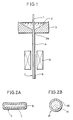
- This sol solution was employed to manufacture a superconducting ceramics elongated body according to the method of the present invention by an apparatus shown in Fig. 1.
- Fig. 1 is a block diagram showing an apparatus for illustrating the embodiment of the first aspect of the manufacturing method according to the present invention.
- the apparatus shown in Fig. 1 is formed by a crucible 3 containing a sol solution 2 and a heating furnace 5.
- a hole 3a is defined in a central portion of the crucible 3, to pass a ceramics elongated substrate 1.
- the sol solution 2 prepared in the aforementioned manner was introduced into the crucible 3.
- a zirconia tape of 50 ⁇ m in thickness and 3 mm in width was employed as the ceramics elongated substrate 1, which was introduced into the crucible 3 from above and passed through the sol solution 2, to be drawn out through the hole 3a of the crucible 3.
- the ceramics elongated substrate 1 thus extracted from the hole 3a of the crucible 3 was provided on its surface with a coating layer 4 by the sol solution 2.
- the thickness of the coating layer 4 was about 1 ⁇ m.
- the ceramics elongated substrate 1 thus provided with the coating layer 4 was then introduced into the downwardly provided heating furnace 5, to be heated up to 800°C.
- the ceramics elongated substrate 1 was then drawn out in the form of a tape-type linear body from a lower portion of the heating furnace, to provide a superconducting ceramics elongated body 7 which was formed on its surface with a superconducting layer 6 of a Y-Ba-Cu-O oxide.
- the superconducting layer of the superconducting ceramics elongated body obtained in the aforementioned manner was analyzed by X-ray diffraction, to recognize that the layer was in K2NiF4 type layer perovskite structure, which is typical crystal structure of high-temperature superconducting ceramics.
- This superconducting ceramics layer superconducted at a temperature exceeding 77 K, the boiling point of liquid nitrogen. Even if the superconducting ceramics layer was bent in a radius of curvature of 30 cm, no breakage of the ceramics elongated body nor cracking in the superconducting layer was caused, while superconductivity of the elongated body was not damaged.
- Fig. 2A is a sectional view showing the tape-type superconducting ceramics elongated body 7 obtained in the aforementioned manner.
- the superconducting layer 6 is provided on the outer peripheral surface of the tape-type ceramics elongated substrate 1.
- the superconducting ceramics elongated body 7 was provided in the form of a tape in this Example, another type of superconducting ceramics elongated body 17 may be prepared by forming a superconducting layer 16 on the surface of a ceramics elongated substrate 11 which is in the form of a round wire, as shown in Fig. 2B.
- a sol solution was prepared similarly to Example 1-1.
- a tape-type ceramics elongated substrate was prepared by a zirconia tape similarly to Example 1-1 and dipped in the sol solution, to be provided with a coating layer of about 1 ⁇ m in thickness.
- the ceramics elongated substrate was taken out from the solution and heated up to 800°C, to be provided on its surface with a superconducting layer of a Y-Ba-Cu-O oxide. Such dipping and heating were repeated several times, to finally obtain a superconducting ceramics elongated body provided with a superconducting layer of 5 ⁇ m in thickness.
- the superconducting ceramics elongated body superconducted at a temperature exceeding 77 K, the boiling point of liquid nitrogen, while no cracking nor disconnection was caused even if the same was bent in a radius of curvature of about 30 cm.
- Fine particles of superconducting ceramics were first prepared as follows: Raw materials were prepared from Y2O3 powder, BaCO3 powder and CuO powder, which were mixed and compression-molded under pressure of 100 atm. at the room temperature under the atmosphere. A compression-molded body thus obtained was preliminarily sintered in an atmosphere containing 760 mmHg of oxygen gas at 940°C for 24 hours. A preliminarily sintered ceramics body thus obtained was pulverized in a ball mill to be 0.5 to 1 ⁇ m in particle size.
- the pulverized fine particles were again compression-molded to repeat preliminary sintering. Such a series of steps were repeated until the ceramics powder was in composition of YBa2Cu3O 6.8 in X-ray diffraction.
- the most preferable condition for the gas atmosphere in preliminary sintering is oxygen gas partial pressure of 760 mmHg, as hereinabove described. However, the oxygen gas partial pressure may be within a range of 200 to 1,000 mmHg. If the oxygen partial pressure is lower than 760 mmHg, nitrogen gas may be mixed to equalize the pressure of the mixed gas to the atmospheric pressure.
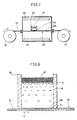
- the superconducting ceramics powder obtained in the aforementioned manner was employed to manufacture a superconducting ceramics elongated body according to the present invention, by an apparatus shown in Fig. 3.
- a ceramics elongated substrate 21 was inserted between rollers 25a and 25b and rightwardly moved in Fig. 3, to pass through a heating furnace 26.
- the ceramics elongated substrate 21 was prepared by a zirconia-tape type wire rod of 3 mm in width and 50 ⁇ m in thickness.
- Superconducting ceramics fine particles 22 were supplied to the upper surface of the ceramics elongated substrate 21 and rolled by the rollers 25a and 25b, to define a layer of 5 ⁇ m in thickness by compression molding on the ceramics elongated substrate 21. Thus, a compression-molded layer 23 was formed by the superconducting ceramics fine particles 22 on the ceramics elongated substrate 21.
- the ceramics elongated substrate 21 thus provided with the compression-molded layer 23 was introduced into the heating furnace 26, in the form of an elongated body 29 coated with the fine particles.
- a heater 27 was provided around the heating furnace 26 to heat the same.
- the heating furnace 26 was provided with an oxygen gas supply port 28a and an oxygen gas exhaust port 28b. Oxygen gas was supplied from the oxygen gas supply port 28a and exhausted from the oxygen gas exhaust port 28b, to provide an oxygen gas atmosphere in the heating furnace 26.
- the pressure of the oxygen gas was controlled to be identical to the atmospheric pressure of 760 mmHg.
- the compression-molded layer 23 was sintered in the heating furnace 26, to provide a superconducting layer 24.
- the ceramics elongated substrate 21 provided with the superconducting layer 24 on its one surface was delivered as a superconducting ceramics elongated body 30.
- the temperature-resistance characteristic of the superconducting ceramics elongated body obtained in the aforementioned manner was measured to confirm that it superconducted at a temperature exceeding 77 K, the boiling point of liquid nitrogen.
- Superconducting ceramics fine particles were prepared similarly to Example 2-1 and compression-molded by rolling as shown in Fig. 4, to be applied to the surface of a zirconia wire of 0.1 mm in diameter.
- numeral 31 indicates a ceramics elongated substrate in the form of a round wire and numeral 33 indicates a comrpession-molded layer.
- the superconducting ceramics fine particles were supplied between rollers 35 and 36 and compressed by the same to form the compression-molded layer 33, thereby to obtain an elongated body 39 coated with the fine particles.
- Fig. 5 is a top plan view showing the rollers 35 and 36.
- other rollers are preferably provided at various angles with respect to the ceramics elongated substrate 31, in order to uniformly compress the periphery thereof.
- Fig. 5 illustrates an exemplary roller 37, which is provided perpendicularly to the rollers 35 and 36.
- the roller 37 forms a counterpart to another roller (not shown), to compress the peripheral surface of the elongated body 39 coated with the fine particles as well as to deliver the same.
- the elongated body 39 coated with the fine particles may be supplied in a twisted manner to pass through a plurality of rollers, so that its peripheral surface is uniformly compressed.
- the compression-molded layer 33 of about 3 ⁇ m in thickness was thus formed by the superconducting ceramics fine particles on the ceramics elongated substrate 31, which was then introduced into a heating furnace under an oxygen atmosphere similarly to that shown in Fig. 3 to sinter the compression-molded layer 33 for providing a superconducting layer, thereby to manufacture a superconducting ceramics elongated body.
- the superconducting ceramics elongated body obtained in the aforementioned manner superconducted at a temperature exceeding 77 K, the boiling point of liquid nitrogen, while no cracking nor disconnection was caused even if the elongated body was bent in a radius of curvature of about 30 cm.
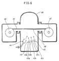
- Fig. 6 is a block diagram showing an exemplary apparatus employed for the method according to the third aspect of the present invention.
- a ceramics elongated substrate 41 is delivered from a supply reel 46 in a vacuum chamber 45. Upon formation of a superconducting layer 48, the ceramics elongated substrate 41 is wound on a take-up reel 47.
- Crucibles 42 containing simple substances or compounds 43 are provided in the vacuum chamber 45, which is decompressed at a high degree of vacuum.
- the crucibles 42 are formed by a plurality of independent crucibles 42a, 42b and 42c, which contain simple substances or compounds 43a, 43b and 43c respectively.
- the respective simple substances or compounds 43a, 43b and 43c contained in the crucibles 42a, 42b and 42c are separately heated to be independently vaporized toward the ceramics elongated substrate 41.
- the simple substances or compounds 43a, 43b and 43c are independently heated under conditions responsive to vapor pressures etc. thereof, so as to control the entire composition of the evaporated simple substances or compounds 43 and that of a superconducting layer formed on the ceramics elongated substrate 41.
- Heating conditions etc. can be appropriately selected in response to vapor pressures, speeds of growth, film thickness etc. of the simple substances or compounds 43 contained in the crucibles 42, while a heating method can be selected from various methods such as resistance heating, electron beam heating, induction heating and the like.
- the crucibles 42 may be arranged in response to the number of elements required for composing a desired superconducting material.
- the simple substances or compounds 43 are evaporated toward the ceramics elongated substrate 41 in the apparatus having the aforementioned structure.
- oxygen ions are applied to the ceramics elongated substrate 41 with the aforementioned evaporation, thereby to produce a desired oxide superconducting material.
- Application of oxygen ions can be performed by ionizing supplied oxygen molecules by an oxygen ion source 44 through a method such as electric field application and applying the ions to the ceramics elongated substrate 41.
- the vacuum evaporation apparatus shown in Fig. 6 was employed, to introduce La2O3 in the crucible 42a, BaO in the crucible 42b and CuO in the crucible 42c respectively in the vacuum chamber 45, which was then decompressed into a high vacuum state.
- the crucibles 42a, 42b and 42c were separately heated to independently adjust atmospheric pressures of the respective materials.
- the temperature of the crucible 42a containing La2O3 was controlled in a range of 1,800 to 2,000 K and that of the crucible 42b containing BaO was controlled in the range of 1,300 to 1,500 K while the temperature of the crucible 42c containing CuO was controlled in a range of 1,000 to 1,300 K.
- the ceramics elongated body 41 was prepared by a tape-type wire rod of zirconia of 3 mm in width and 50 ⁇ m in thickness.
- the ceramics elongated substrate 41 was delivered from the supply reel 46.
- an oxide superconducting layer 40 of about 3 ⁇ m in thickness was formed on the ceramics elongated substrate 41.
- the ceramics elongated substrate 41 provided with the superconducting layer 48 was wound on the take-up reel 47.
- the temperature-resistance characteristic of the superconducting ceramics elongated body obtained in the aforementioned manner was measured to confirm that it superconducted at a temperature exceeding 77 K, the boiling point of liquid nitrogen.
- Example 3-1 An apparatus similar to that of Example 3-1 was employed to introduce La in the crucible 42a, Ba in the crucible 42b and Cu in the crucible 42c respectively.
- the crucibles 42a, 42b and 42c were independently heated/temperature-controlled.
- the temperature of the crucible 42a containing La was controlled in a range of 1,400 to 1,600 K and that of the crucible 42b containing Ba was controlled in a range of 500 to 700 K, while the temperature of the crucible 42c containing Cu was controlled in a range of 1,100 to 1,200 K.
- the ceramics elongated substrate 41 was prepared by a material which was similar to that in Example 3-1.
- the materials in the crucibles 42a, 42b and 42c were independently evaporated while applying oxygen ions from the oxygen ion source 44 toward the ceramics elongated substrate 41 similarly to Example 3-1, thereby to form an oxide superconducting layer 48 on the ceramics elongated substrate 41.
- Fig. 7 is a block diagram showing an apparatus for illustrating an embodiment of the fourth aspect of the method according to the present invention.
- Fig. 8 is an enlarged sectional view of a crucible 55 shown in Fig. 7.
- a ceramics elongated substrate 51 supplied from a supply reel 52 passes through an oxygen atmosphere furnace 54, to be wound on a take-up reel 53.
- the crucible 55, containing a fluoride solution 56 is set on the ceramics elongated substrate 1.
- Raw-material oxides 57 are supplied on the fluoride solution 56.
- an upper portion of the fluoride solution 56 is at a temperature T1 while its lower portion, which is in contact with the surface of the ceramics elongated substrate 51, is at a temperature T2.
- Such a temperature gradient in the fluoride solution 56 is controlled by heaters 60 and 61, which are provided in upper and lower parts of the oxygen atmosphere furnace 54.
- the raw-material oxides were prepared by mixed powder of oxides containing 1 mol of YO 1.5 , 2 mols of BaO and 3 mols of CuO, and the fluoride solution was prepared by a fluoride containing 1 mol of YF3, 2 mols of BaF2 and 3 mols of CuF2.
- a fluoride mixed in such a ratio is generally molten in a temperature range of 1,300 to 1,150°C, while the fluoride was molten at 1,200°C in this Example.
- the mixed powder of the above oxides was supplied in the form of the raw-material oxides 57 on the fluoride solution 56.
- the temperature at the bottom portion of the crucible 55 was 1,100°C, and the heaters 60 and 61 were so controlled that the temperature T1 at the upper portion of the crucible 55 was 1,200°C and the temperature T2 at the lower portion, being in contact with the ceramics elongated substrate 51, was 1,150°C. It is to be noted that, when the temperature T1 is changed within a range of 1,300 to 1,150°C, the temperature at the bottom portion of the crucible 55 is preferably changed in a range of 1,200 to 980°C responsively.
- the ceramics elongated substrate 51 was prepared by a zirconia tape of 3 mm in width and 50 ⁇ m in thickness.
- the crucible 55 was made of platinum in this Example, a gold one is also employable.
- Oxygen gas partial pressure in the oxygen atmosphere furnace 54 was controlled to be 760 mmHg.
- the raw-material oxides 57 supplied on the fluoride solution 56 were dissolved in the fluoride solution 56.
- the process of such dissolution was not clear but it can be presumed that a composite oxide having a low melting point was formed by the raw-material oxides 57 and dissolved in the fluoride solution 56.
- the raw-material oxides 57 supplied to the fluoride solution 56 were rendered reactive between themselves, to produce a composite oxide composing a superconducting ceramics material.
- the fluoride solution 56 was set in the temperature gradient of T1 to T2, so that the surface of the ceramics elongated substrate 51 was under the temperature T2. Therefore, the composite oxide forming the superconducting ceramics material was saturated in the vicinity of the ceramics elongated substrate 51 to be deposited on the same, thereby to form the superconducting layer 58.
- Such a superconducting layer 58 was formed on the ceramics elongated substrate 51, which was continuously moved in a direction A. Thus, the superconducting layer 58 was continuously formed on the ceramics elongated substrate 51 and delivered as a superconducting ceramics elongated body 59, to be wound on the take-up reel 53.
- the temperature-resistance characteristic of the superconducting ceramics elongated body obtained in the above manner was measured to recognize that it superconducted at a temperature exceeding 77 K, the boiling point of liquid nitrogen.
- the fourth aspect of the present invention is not restricted to formation of the superconducting layer under such an oxygen atmosphere.
- the fluoride solution 56 may be slightly adhered to the superconducting layer 58 deposited on the surface of the ceramics elongated substrate 51. However, such adhesion causes no problem so far as the solution is prepared by a fluoride which exerts no bad influence on the superconducting ceramics material, as in the Example. Further, the fluoride adhered to the superconducting layer can be converted into an oxide under an oxygen atmosphere, as in the Example.
- Fig. 9 is a block diagram showing an apparatus for illustrating the method according to the fifth aspect of the present invention.
- the apparatus shown in Fig. 9 is formed by a melting furnace 74 and an oxygen gas atmosphere furnace 84, and a gold crucible 73 is provided in the melting furnace 74.
- a fluoride solution 72 prepared by a mixture is contained in the gold crucible 73.
- a hole 73a is defined in a central portion of the gold crucible 73, so that a ceramics elongated substrate 71 passes through the hole 73a.
- a heater 75 for heating the fluoride solution 72 is provided around the melting furnace 74.
- the melting furnace 74 is provided with an inert gas supply port 76 and an inert gas exhaust port 77.
- Another heater 85 is provided around the oxygen gas atmosphere furnace 84 to control the temperature in the furnace.
- the oxygen gas atmosphere furnace 84 is provided with an oxygen gas supply port 86 and an oxygen gas exhaust port 87.
- a mixture of fluorides, containing 1 mol of YF3, 2 mols of BaF2 and 3 mols of CuF2 was introduced into the gold crucible 73 and heated by the heater 75 to be molten at a temperature of 950°C, thereby to provide the fluoride solution 72.
- Viscosity of the fluoride solution 72 was 10 to 100 cps.
- Inert gas was prepared by argon gas, which was supplied from the inert gas supply port 76 and exhausted from the inert gas exhaust port 77, to provide an argon gas atmosphere in the melting furnace 74.
- a zirconia tape of 50 ⁇ m in thickness was employed as the ceramics elongated substrate 71, which was introduced into the melting furnace 74 from above to pass through the fluoride solution 72, and extracted from a lower portion of the melting furnace 74 through the hole 73a of the gold crucible 73.
- Coating layers 78 of the fluoride solution 72 were provided on both surfaces of the ceramics elongated substrate 71 thus extracted from the hole 73a of the crucible 73.
- the thickness of each coating layer 78 was about 5 ⁇ m.
- the ceramics elongated substrate 71 thus provided with the coating layers 78 was then introduced into the oxygen gas atmosphere furnace 84.
- oxygen gas was supplied from the oxygen gas supply port 86 and exhausted from the oxygen gas exhaust port 87, so that oxygen gas partial pressure was 760 mmHg.
- the oxygen gas atmosphere furnace 84 was heated and temperature-controlled by the heater 85. Fluorine contained in the fluorides forming the coating layers 78 was replaced by oxygen in the oxygen gas atmosphere furnace 84, whereby composition of the coating layers 78 was converted into that of superconducting ceramics.
- the ceramics elongated substrate 71, thus provided with the coating layers 78 composed of superconducting ceramics was extracted from the oxygen gas atmosphere furnace 84 as a superconducting ceramics elongated body 90.
- the coating layers of the superconducting ceramics elongated body obtained in the aforementioned manner were analyzed by powder X-ray diffraction, to recognize that crystals forming the coating layers were in K2NiF4 type perovskite structure, which is typical crystal structure of high-temperature superconducting ceramics.
- the superconducting ceramics elongated body superconducted at the temperature of liquid nitrogen.
- the coating layers were formed on both surfaces of the tape-type ceramics elongated substrate, such a coating layer may be formed only on one surface. Further, the tape-type ceramics elongated substrate may be replaced by that in the form of a round wire. A mixture of fluoride fine particles may be applied to a substrate to be heated/molten upon application, and then heated under an oxygen gas atmosphere to convert the composition of the coating layer into that of superconducting ceramics.
- Fig. 10 is an enlarged sectional view showing the embodiment of the superconducting ceramics elongated body having a protective layer.
- the superconducting ceramics elongated body shown in Fig. 10 comprises a tape-type elongated substrate 101, which is formed of ceramics to have flexibility.
- the elongated substrate 101 extends in a direction perpendicular to the plane of Fig. 10.
- a superconducting layer 103 is formed on one major surface 102 of the elongated substrate 101.
- the superconducting layer 103 is formed of oxide ceramics, and extends longitudinally along the elongated substrate 101.
- a protective layer 104 which is formed of ceramics containing a nitride.
- the protective layer 104 is in contact with both side edges of the major surface 102 of the elongated substrate 101, in order to cover the entire periphery of the superconducting layer 103, i.e., not only the upper surface but also the side surfaces of the superconducting layer 103, with the elongated substrate 101.
- a zirconia tape of 5 mm in width and 100 ⁇ m in thickness was prepared as the elongated substrate 101.
- the protective layer 104 was formed by magnetron type reactive high-frequency sputtering under conditions of the degree of vacuum of 10 ⁇ 2 to 10 ⁇ 3 Torr. and making power of 200 W.
- the protective layer 104 was prepared by Si3N4 or "sialon". In the sputtering process, the ratio of N to Ar in the atmosphere was 0.5 when Si3N4 was employed, while the ratio of (N + O) to Ar was 0.5 when "sialon" was employed.
- the superconducting ceramics elongated body thus obtained was introduced into a constant temperature/constant humidity bath having a temperature of 50°C and relative humidity of 95 %, to examine its moisture resistance.
- a reference example was prepared by an elongated body provided with no protective layer.
- Example and reference example superconducted at the temperature of liquid nitrogen immediately after formation.
- the superconducting layer was partially peeled off in the so-called disconnected state after introduction into the constant temperature/constant humidity bath for 24 hours.
- the superconducting ceramics elongated body provided with the protective layer maintained its superconductivity, which was attained immediately after formation, even if 48 hours were passed in the constant temperature/constant humidity bath.
- the samples were bent in a prescribed radius of curvature, for evaluation of flexibility.
- no disconnection was caused in the superconducting layers upon bending in a radius of curvature of 30 cm, and the superconducting states were maintained in the superconducting layers.
- the protective layer 104 was also adapted to improve mechanical strength of the superconducting ceramics elongated body.
- Fig. 11 is an enlarged sectional view showing another embodiment of the superconducting ceramics elongated body having a protective layer according to the present invention.
- an elongated substrate 111 is provided in the form of a round wire, and a superconducting layer 112 is formed to cover its outer peripheral surface. Further, a protective layer 113 is formed to cover the outer peripheral surface of the superconducting layer 112.
- a superconducting layer 112 is formed to cover its outer peripheral surface.
- a protective layer 113 is formed to cover the outer peripheral surface of the superconducting layer 112.
- Other structure of this embodiment is similar to that of the embodiment shown in Fig. 10, and hence redundant description is omitted.
- the entire sectional configuration of the superconducting ceramics elongated body according to the present invention and sectional configurations of the elongated substrate, the superconducting layer and the protective layer forming the same are not restricted to those described above, but may be arbitrarily modified.
- the superconducting ceramics elongated body according to the present invention is flexible since the superconducting layer is formed on at least a part of the surface of the flexible ceramics elongated substrate.
- the superconducting ceramics elongated body according to the present invention which can be wound on a reel, for example, is highly practicable.
- the superconducting ceramics elongated body according to the present invention is not restricted to a power transmission medium in the field of energy, but is also applicable to a switching element, a storage device, a magnetic flux sensor, an amplifying element or the like, which is employed as a device in the field of electronics.
Landscapes
- Chemical & Material Sciences (AREA)
- Engineering & Computer Science (AREA)
- Ceramic Engineering (AREA)
- Organic Chemistry (AREA)
- Manufacturing & Machinery (AREA)
- Materials Engineering (AREA)
- Structural Engineering (AREA)
- Inorganic Chemistry (AREA)
- Superconductors And Manufacturing Methods Therefor (AREA)
- Inorganic Compounds Of Heavy Metals (AREA)
- Compositions Of Oxide Ceramics (AREA)
- Oxygen, Ozone, And Oxides In General (AREA)
Priority Applications (3)
| Application Number | Priority Date | Filing Date | Title |
|---|---|---|---|
| EP95120042A EP0725448A3 (de) | 1987-08-20 | 1988-08-18 | Supraleitender keramischer verlängerter Gegenstand und dessen Herstellungsverfahren |
| EP95102180A EP0661763B1 (de) | 1987-08-20 | 1988-08-18 | Verfahren zur Herstellung länglicher Festkörper aus supraleitender Keramik |
| EP95102184A EP0657949B1 (de) | 1987-08-20 | 1988-08-18 | Verfahren zur Herstellung eines länglichen Festkörpers aus supraleitender Keramik |
Applications Claiming Priority (12)
| Application Number | Priority Date | Filing Date | Title |
|---|---|---|---|
| JP207743/87 | 1987-08-20 | ||
| JP207744/87 | 1987-08-20 | ||
| JP20774487 | 1987-08-20 | ||
| JP20774387 | 1987-08-20 | ||
| JP20892587 | 1987-08-21 | ||
| JP208924/87 | 1987-08-21 | ||
| JP208925/87 | 1987-08-21 | ||
| JP20892487 | 1987-08-21 | ||
| JP208887/87 | 1987-08-22 | ||
| JP20888687 | 1987-08-22 | ||
| JP208886/87 | 1987-08-22 | ||
| JP20888787 | 1987-08-22 |
Related Child Applications (5)
| Application Number | Title | Priority Date | Filing Date |
|---|---|---|---|
| EP95102184A Division EP0657949B1 (de) | 1987-08-20 | 1988-08-18 | Verfahren zur Herstellung eines länglichen Festkörpers aus supraleitender Keramik |
| EP95102180A Division EP0661763B1 (de) | 1987-08-20 | 1988-08-18 | Verfahren zur Herstellung länglicher Festkörper aus supraleitender Keramik |
| EP95102180.7 Division-Into | 1995-02-16 | ||
| EP95102184.9 Division-Into | 1995-02-16 | ||
| EP95120042.7 Division-Into | 1995-12-19 |
Publications (3)
| Publication Number | Publication Date |
|---|---|
| EP0304061A2 true EP0304061A2 (de) | 1989-02-22 |
| EP0304061A3 EP0304061A3 (de) | 1992-06-10 |
| EP0304061B1 EP0304061B1 (de) | 1997-10-29 |
Family
ID=27553839
Family Applications (4)
| Application Number | Title | Priority Date | Filing Date |
|---|---|---|---|
| EP95120042A Withdrawn EP0725448A3 (de) | 1987-08-20 | 1988-08-18 | Supraleitender keramischer verlängerter Gegenstand und dessen Herstellungsverfahren |
| EP88113445A Expired - Lifetime EP0304061B1 (de) | 1987-08-20 | 1988-08-18 | Länglicher Formkörper aus supraleitender Keramik und Verfahren zu seiner Herstellung |
| EP95102180A Expired - Lifetime EP0661763B1 (de) | 1987-08-20 | 1988-08-18 | Verfahren zur Herstellung länglicher Festkörper aus supraleitender Keramik |
| EP95102184A Expired - Lifetime EP0657949B1 (de) | 1987-08-20 | 1988-08-18 | Verfahren zur Herstellung eines länglichen Festkörpers aus supraleitender Keramik |
Family Applications Before (1)
| Application Number | Title | Priority Date | Filing Date |
|---|---|---|---|
| EP95120042A Withdrawn EP0725448A3 (de) | 1987-08-20 | 1988-08-18 | Supraleitender keramischer verlängerter Gegenstand und dessen Herstellungsverfahren |
Family Applications After (2)
| Application Number | Title | Priority Date | Filing Date |
|---|---|---|---|
| EP95102180A Expired - Lifetime EP0661763B1 (de) | 1987-08-20 | 1988-08-18 | Verfahren zur Herstellung länglicher Festkörper aus supraleitender Keramik |
| EP95102184A Expired - Lifetime EP0657949B1 (de) | 1987-08-20 | 1988-08-18 | Verfahren zur Herstellung eines länglichen Festkörpers aus supraleitender Keramik |
Country Status (4)
| Country | Link |
|---|---|
| US (1) | US5112802A (de) |
| EP (4) | EP0725448A3 (de) |
| JP (1) | JP2557486B2 (de) |
| DE (3) | DE3856170T2 (de) |
Cited By (7)
| Publication number | Priority date | Publication date | Assignee | Title |
|---|---|---|---|---|
| EP0385132A1 (de) * | 1989-02-04 | 1990-09-05 | Sumitomo Electric Industries, Ltd. | Supraleitender Draht |
| EP0431782A1 (de) * | 1989-12-04 | 1991-06-12 | Minnesota Mining And Manufacturing Company | Mit einem Supraleiter beschichtete, flexible Fasern |
| US5089455A (en) * | 1989-08-11 | 1992-02-18 | Corning Incorporated | Thin flexible sintered structures |
| US5104850A (en) * | 1990-02-28 | 1992-04-14 | The United States Of America As Represented By The Secretary Of The Navy | Preparation of high temperature superconducting coated wires by dipping and post annealing |
| US5122509A (en) * | 1990-04-30 | 1992-06-16 | Advanced Technology Materials, Inc. | High temperature superconductor/diamond composite article, and method of making the same |
| US5151407A (en) * | 1990-02-28 | 1992-09-29 | The United States Of America As Represented By The Secretary Of The Navy | Method of producing Bi-Sr-Ca-Cu-O superconducting materials in cast form |
| EP0718897A1 (de) * | 1994-12-19 | 1996-06-26 | Hitachi, Ltd. | Supraleitender Draht der Thallium-Gruppe |
Families Citing this family (9)
| Publication number | Priority date | Publication date | Assignee | Title |
|---|---|---|---|---|
| US5041321A (en) * | 1984-11-02 | 1991-08-20 | The Boeing Company | Fiberformed ceramic insulation and method |
| US5589441A (en) * | 1984-11-02 | 1996-12-31 | The Boeing Company | Superconductive fiberform ceramic composite |
| JPS63250881A (ja) * | 1987-04-07 | 1988-10-18 | Semiconductor Energy Lab Co Ltd | 超電導体の作製方法 |
| JP2651481B2 (ja) * | 1987-09-21 | 1997-09-10 | 株式会社 半導体エネルギー研究所 | 超伝導材料の作製方法 |
| JP3881732B2 (ja) * | 1996-10-16 | 2007-02-14 | 財団法人国際超電導産業技術研究センター | 酸化物超電導体複合体の製造方法 |
| US8361931B2 (en) * | 2012-01-04 | 2013-01-29 | Masoud Salavati-Niasari | Method for preparing yttrium barium copper oxide (YBCO) superconducting nanoparticles |
| US9257628B2 (en) * | 2012-03-21 | 2016-02-09 | Basf Se | Process for producing nanoparticles and their use in the production of high-temperature superconductors |
| CN104271310B (zh) * | 2012-05-08 | 2016-04-27 | 新日铁住金株式会社 | 超高强度钢焊接用药芯焊丝 |
| WO2022194354A1 (en) * | 2021-03-16 | 2022-09-22 | Ceramic Data Solutions GmbH | Data carrier, reading method and system utilizing super resolution techniques |
Family Cites Families (27)
| Publication number | Priority date | Publication date | Assignee | Title |
|---|---|---|---|---|
| US4014706A (en) * | 1972-05-12 | 1977-03-29 | Research Enterprises Corporation | Solid solution ceramic materials |
| US3861947A (en) * | 1972-10-02 | 1975-01-21 | Union Carbide Corp | Process for the preparation of zircon coated zirconia fibers |
| FR2275032A1 (fr) * | 1974-06-14 | 1976-01-09 | Siemens Ag | Procede pour fabriquer un supraconducteur comportant un compose intermetallique, supraconducteur, constitue par au moins deux elements |
| US4411959A (en) * | 1981-08-17 | 1983-10-25 | Westinghouse Electric Corp. | Submicron-particle ductile superconductor |
| US4419125A (en) * | 1982-10-22 | 1983-12-06 | Westinghouse Electric Corp. | Method for the preparation of brittle superconducting material in ultrafine particle form |
| US4485094A (en) * | 1983-01-28 | 1984-11-27 | Westinghouse Electric Corp. | Method of making ABO3 of the cubic perovskite structure |
| FR2567120B1 (fr) * | 1984-07-05 | 1991-08-23 | United Technologies Corp | Revetements composites sic/si3n4 pour matieres composites carbone-carbone |
| US4636480A (en) * | 1985-01-18 | 1987-01-13 | General Electric Company | Composite by infiltration |
| JPS61291445A (ja) * | 1985-06-18 | 1986-12-22 | イソライト工業株式会社 | セラミツクフアイバ−ブランケツトの処理方法 |
| US4888202A (en) * | 1986-07-31 | 1989-12-19 | Nippon Telegraph And Telephone Corporation | Method of manufacturing thin compound oxide film and apparatus for manufacturing thin oxide film |
| CA1288644C (en) * | 1987-02-26 | 1991-09-10 | Noriyuki Yoshida | Oxide superconductive material and method of manufacturing the same |
| JP2527179B2 (ja) * | 1987-03-26 | 1996-08-21 | 日本電信電話株式会社 | 超伝導性複合材の作製方法 |
| CA1332324C (en) * | 1987-03-30 | 1994-10-11 | Jun Shioya | Method for producing thin film of oxide superconductor |
| JPS63250017A (ja) * | 1987-04-06 | 1988-10-17 | Fujikura Ltd | 超伝導線材及びその製造方法 |
| JPS63250018A (ja) * | 1987-04-06 | 1988-10-17 | Fujikura Ltd | 超伝導線材及びその製造方法 |
| JPS63276810A (ja) * | 1987-05-06 | 1988-11-15 | Fujikura Ltd | 超電導線 |
| JPS63277770A (ja) * | 1987-05-09 | 1988-11-15 | Nippon Soda Co Ltd | 超電導セラミックス薄膜形成用組成物および超電導セラミックス薄膜の製造方法 |
| IL86316A0 (en) * | 1987-05-15 | 1988-11-15 | Ppg Industries Inc | Formation of superconductive ceramic oxides by chemical polymerization |
| US4925829A (en) * | 1987-05-26 | 1990-05-15 | Sumitomo Electric Industries, Ltd. | Method for preparing thin film of compound oxide superconductor by ion beam techniques |
| JPS63303850A (ja) * | 1987-06-03 | 1988-12-12 | Kobe Steel Ltd | 酸化物系超電導材料の製造方法 |
| JPS6411305A (en) * | 1987-07-06 | 1989-01-13 | Sumitomo Electric Industries | Superconducting coil and manufacture thereof |
| JPS6412414A (en) * | 1987-07-06 | 1989-01-17 | Fujikura Ltd | Superconducting wire or oxide |
| EP0298866B1 (de) * | 1987-07-06 | 1996-05-01 | Sumitomo Electric Industries Limited | Supraleitende dünne Schicht und Verfahren zu ihrer Herstellung |
| EP0299879B1 (de) * | 1987-07-17 | 1994-06-08 | Sumitomo Electric Industries Limited | Supraleitende Dünnschicht und Verfahren zu deren Herstellung |
| KR910007382B1 (ko) * | 1987-08-07 | 1991-09-25 | 가부시기가이샤 히다찌세이사꾸쇼 | 초전도 재료 및 초전도 박막의 제조방법 |
| US4975413A (en) * | 1987-08-12 | 1990-12-04 | Amoco Corporation | Superconductor-coated carbon fiber composites |
| JPS6448315A (en) * | 1987-08-14 | 1989-02-22 | Hitachi Metals Ltd | High temperature superconductor |
-
1988
- 1988-08-15 JP JP63202940A patent/JP2557486B2/ja not_active Expired - Lifetime
- 1988-08-18 EP EP95120042A patent/EP0725448A3/de not_active Withdrawn
- 1988-08-18 EP EP88113445A patent/EP0304061B1/de not_active Expired - Lifetime
- 1988-08-18 DE DE3856170T patent/DE3856170T2/de not_active Expired - Fee Related
- 1988-08-18 DE DE3856156T patent/DE3856156T2/de not_active Expired - Fee Related
- 1988-08-18 EP EP95102180A patent/EP0661763B1/de not_active Expired - Lifetime
- 1988-08-18 DE DE3856056T patent/DE3856056T2/de not_active Expired - Fee Related
- 1988-08-18 EP EP95102184A patent/EP0657949B1/de not_active Expired - Lifetime
- 1988-08-22 US US07/234,643 patent/US5112802A/en not_active Expired - Fee Related
Cited By (10)
| Publication number | Priority date | Publication date | Assignee | Title |
|---|---|---|---|---|
| EP0385132A1 (de) * | 1989-02-04 | 1990-09-05 | Sumitomo Electric Industries, Ltd. | Supraleitender Draht |
| US5143898A (en) * | 1989-02-04 | 1992-09-01 | Sumitomo Electric Industries, Ltd. | Superconducting wire |
| US5089455A (en) * | 1989-08-11 | 1992-02-18 | Corning Incorporated | Thin flexible sintered structures |
| EP0472789A1 (de) * | 1989-08-11 | 1992-03-04 | Corning Incorporated | Gesinterte, dünne, biegsame Struktur |
| EP0431782A1 (de) * | 1989-12-04 | 1991-06-12 | Minnesota Mining And Manufacturing Company | Mit einem Supraleiter beschichtete, flexible Fasern |
| US5104850A (en) * | 1990-02-28 | 1992-04-14 | The United States Of America As Represented By The Secretary Of The Navy | Preparation of high temperature superconducting coated wires by dipping and post annealing |
| US5151407A (en) * | 1990-02-28 | 1992-09-29 | The United States Of America As Represented By The Secretary Of The Navy | Method of producing Bi-Sr-Ca-Cu-O superconducting materials in cast form |
| US5122509A (en) * | 1990-04-30 | 1992-06-16 | Advanced Technology Materials, Inc. | High temperature superconductor/diamond composite article, and method of making the same |
| EP0718897A1 (de) * | 1994-12-19 | 1996-06-26 | Hitachi, Ltd. | Supraleitender Draht der Thallium-Gruppe |
| US5849670A (en) * | 1994-12-19 | 1998-12-15 | Hitachi, Ltd. | Thallium group superconducting wire |
Also Published As
| Publication number | Publication date |
|---|---|
| DE3856170T2 (de) | 1998-08-27 |
| EP0657949A1 (de) | 1995-06-14 |
| JP2557486B2 (ja) | 1996-11-27 |
| DE3856056D1 (de) | 1997-12-04 |
| DE3856170D1 (de) | 1998-06-04 |
| DE3856156T2 (de) | 1998-08-06 |
| EP0661763B1 (de) | 1998-04-01 |
| EP0725448A3 (de) | 1997-01-15 |
| DE3856056T2 (de) | 1998-06-10 |
| EP0304061B1 (de) | 1997-10-29 |
| EP0657949B1 (de) | 1998-04-29 |
| EP0661763A1 (de) | 1995-07-05 |
| US5112802A (en) | 1992-05-12 |
| EP0304061A3 (de) | 1992-06-10 |
| JPH01144518A (ja) | 1989-06-06 |
| DE3856156D1 (de) | 1998-05-07 |
| EP0725448A2 (de) | 1996-08-07 |
Similar Documents
| Publication | Publication Date | Title |
|---|---|---|
| US5112802A (en) | Superconducting ceramics elongated body and method of manufacturing the same | |
| CA1332324C (en) | Method for producing thin film of oxide superconductor | |
| JP2567460B2 (ja) | 超伝導薄膜とその作製方法 | |
| US4921833A (en) | Superconducting member | |
| EP0285030B1 (de) | Verfahren zur Herstellung von dünnen supraleitenden Schichten | |
| WO2001026165A2 (en) | Method and apparatus for forming buffer layers | |
| EP0292958B1 (de) | Verfahren zur Herstellung einer dünnen Schicht aus supraleitendem Mischoxid | |
| JP2711253B2 (ja) | 超伝導膜及びその形成方法 | |
| EP0328333A2 (de) | Verfahren zur Herstellung von supraleitenden Keramiken | |
| US5273954A (en) | Method for forming superconducting ceramics elongated body | |
| EP0431782A1 (de) | Mit einem Supraleiter beschichtete, flexible Fasern | |
| US5232909A (en) | Method for manufacturing superconducting ceramics elongated body | |
| EP0277885B1 (de) | Verfahren zum Herstellen einer supraleitenden Dünnschicht | |
| EP0345358A1 (de) | Targetmaterial zur bildung eines supraleitenden films | |
| US5646097A (en) | Method of fabricating a (1223) Tl-Ba-Ca-Cu-O superconductor | |
| US4914080A (en) | Method for fabricating superconductive film | |
| EP0333513B1 (de) | Oxid-Supraleiter | |
| EP0511391B1 (de) | Verfahren zum herstellen eines supraleitenden films | |
| US5126320A (en) | Method for manufacturing an oxide superconducting thin-film | |
| JPS63274024A (ja) | 超電導薄膜の作製方法 | |
| JP2502344B2 (ja) | 複合酸化物超電導体薄膜の作製方法 | |
| Davis et al. | A flash evaporation technique for oxide superconductors | |
| JPH01220311A (ja) | 超電導セラミック線材の製造法 | |
| JPH0764679B2 (ja) | セラミックス超電導体薄膜の製造方法 | |
| JPH01183176A (ja) | 超電導薄膜の製造方法 |
Legal Events
| Date | Code | Title | Description |
|---|---|---|---|
| PUAI | Public reference made under article 153(3) epc to a published international application that has entered the european phase |
Free format text: ORIGINAL CODE: 0009012 |
|
| AK | Designated contracting states |
Kind code of ref document: A2 Designated state(s): DE FR GB |
|
| 17P | Request for examination filed |
Effective date: 19901220 |
|
| PUAL | Search report despatched |
Free format text: ORIGINAL CODE: 0009013 |
|
| AK | Designated contracting states |
Kind code of ref document: A3 Designated state(s): DE FR GB |
|
| 17Q | First examination report despatched |
Effective date: 19940802 |
|
| RAP1 | Party data changed (applicant data changed or rights of an application transferred) |
Owner name: SUMITOMO ELECTRIC INDUSTRIES, LTD. |
|
| GRAG | Despatch of communication of intention to grant |
Free format text: ORIGINAL CODE: EPIDOS AGRA |
|
| GRAH | Despatch of communication of intention to grant a patent |
Free format text: ORIGINAL CODE: EPIDOS IGRA |
|
| GRAH | Despatch of communication of intention to grant a patent |
Free format text: ORIGINAL CODE: EPIDOS IGRA |
|
| GRAA | (expected) grant |
Free format text: ORIGINAL CODE: 0009210 |
|
| AK | Designated contracting states |
Kind code of ref document: B1 Designated state(s): DE FR GB |
|
| DX | Miscellaneous (deleted) | ||
| ET | Fr: translation filed | ||
| REF | Corresponds to: |
Ref document number: 3856056 Country of ref document: DE Date of ref document: 19971204 |
|
| PLBE | No opposition filed within time limit |
Free format text: ORIGINAL CODE: 0009261 |
|
| STAA | Information on the status of an ep patent application or granted ep patent |
Free format text: STATUS: NO OPPOSITION FILED WITHIN TIME LIMIT |
|
| 26N | No opposition filed | ||
| PGFP | Annual fee paid to national office [announced via postgrant information from national office to epo] |
Ref country code: FR Payment date: 19990810 Year of fee payment: 12 |
|
| PGFP | Annual fee paid to national office [announced via postgrant information from national office to epo] |
Ref country code: GB Payment date: 19990818 Year of fee payment: 12 |
|
| PGFP | Annual fee paid to national office [announced via postgrant information from national office to epo] |
Ref country code: DE Payment date: 19990823 Year of fee payment: 12 |
|
| PG25 | Lapsed in a contracting state [announced via postgrant information from national office to epo] |
Ref country code: GB Free format text: LAPSE BECAUSE OF NON-PAYMENT OF DUE FEES Effective date: 20000818 |
|
| GBPC | Gb: european patent ceased through non-payment of renewal fee |
Effective date: 20000818 |
|
| PG25 | Lapsed in a contracting state [announced via postgrant information from national office to epo] |
Ref country code: FR Free format text: LAPSE BECAUSE OF NON-PAYMENT OF DUE FEES Effective date: 20010430 |
|
| PG25 | Lapsed in a contracting state [announced via postgrant information from national office to epo] |
Ref country code: DE Free format text: LAPSE BECAUSE OF NON-PAYMENT OF DUE FEES Effective date: 20010501 |
|
| REG | Reference to a national code |
Ref country code: FR Ref legal event code: ST |