EP0304103A1 - Scheibenbremszange für ein Fahrzeug - Google Patents
Scheibenbremszange für ein Fahrzeug Download PDFInfo
- Publication number
- EP0304103A1 EP0304103A1 EP88201548A EP88201548A EP0304103A1 EP 0304103 A1 EP0304103 A1 EP 0304103A1 EP 88201548 A EP88201548 A EP 88201548A EP 88201548 A EP88201548 A EP 88201548A EP 0304103 A1 EP0304103 A1 EP 0304103A1
- Authority
- EP
- European Patent Office
- Prior art keywords
- piston
- cylinder head
- brake
- dome
- skirt
- Prior art date
- Legal status (The legal status is an assumption and is not a legal conclusion. Google has not performed a legal analysis and makes no representation as to the accuracy of the status listed.)
- Granted
Links
- 239000000463 material Substances 0.000 claims abstract description 13
- 239000002184 metal Substances 0.000 claims description 5
- 230000001681 protective effect Effects 0.000 claims description 4
- 238000004873 anchoring Methods 0.000 claims description 3
- 238000010008 shearing Methods 0.000 claims description 2
- 238000000034 method Methods 0.000 abstract description 8
- 230000008569 process Effects 0.000 abstract description 2
- 229910000831 Steel Inorganic materials 0.000 abstract 1
- 239000010959 steel Substances 0.000 abstract 1
- 238000009966 trimming Methods 0.000 abstract 1
- 238000004519 manufacturing process Methods 0.000 description 5
- 230000006835 compression Effects 0.000 description 4
- 238000007906 compression Methods 0.000 description 4
- 238000003754 machining Methods 0.000 description 4
- 230000008901 benefit Effects 0.000 description 3
- 230000009471 action Effects 0.000 description 2
- 238000005452 bending Methods 0.000 description 2
- 238000000641 cold extrusion Methods 0.000 description 2
- 238000001125 extrusion Methods 0.000 description 2
- 238000009434 installation Methods 0.000 description 2
- 239000007788 liquid Substances 0.000 description 2
- 230000004048 modification Effects 0.000 description 2
- 238000012986 modification Methods 0.000 description 2
- 230000009467 reduction Effects 0.000 description 2
- 239000011265 semifinished product Substances 0.000 description 2
- 238000010521 absorption reaction Methods 0.000 description 1
- 238000011109 contamination Methods 0.000 description 1
- 238000005520 cutting process Methods 0.000 description 1
- 230000000694 effects Effects 0.000 description 1
- 230000005489 elastic deformation Effects 0.000 description 1
- 230000002349 favourable effect Effects 0.000 description 1
- 230000002093 peripheral effect Effects 0.000 description 1
- 230000001131 transforming effect Effects 0.000 description 1
- 239000013585 weight reducing agent Substances 0.000 description 1
Images
Classifications
-
- F—MECHANICAL ENGINEERING; LIGHTING; HEATING; WEAPONS; BLASTING
- F16—ENGINEERING ELEMENTS AND UNITS; GENERAL MEASURES FOR PRODUCING AND MAINTAINING EFFECTIVE FUNCTIONING OF MACHINES OR INSTALLATIONS; THERMAL INSULATION IN GENERAL
- F16D—COUPLINGS FOR TRANSMITTING ROTATION; CLUTCHES; BRAKES
- F16D65/00—Parts or details
- F16D65/14—Actuating mechanisms for brakes; Means for initiating operation at a predetermined position
-
- F—MECHANICAL ENGINEERING; LIGHTING; HEATING; WEAPONS; BLASTING
- F16—ENGINEERING ELEMENTS AND UNITS; GENERAL MEASURES FOR PRODUCING AND MAINTAINING EFFECTIVE FUNCTIONING OF MACHINES OR INSTALLATIONS; THERMAL INSULATION IN GENERAL
- F16D—COUPLINGS FOR TRANSMITTING ROTATION; CLUTCHES; BRAKES
- F16D2125/00—Components of actuators
- F16D2125/02—Fluid-pressure mechanisms
- F16D2125/06—Pistons
Definitions
- This invention relates to a piston intended to be included as an operative member in a disc brake caliper for a vehicle.
- the piston constituting the operative member of a disc brake calliper has the purpose of transforming the hydraulic pressure produced in the liquid of the braking system by the actuation of the brake pedal, into a force which must be applied to the friction linings which apply the brake disc, in order to generate the friction force which gives rise to the braking action.
- the force which must thus be produced by the piston is very high, taking into account the intensity of the braking action required and the fairly small radius on which the friction linings work. It is therefore necessary to provide for a high stress on the cylinder head of the piston.
- the cylinder head must have sufficient mechanical strength to withstand this stressing, and in addition it must also have great rigidity, that is to say, it must be subjected, when stressed, to a very reduced elastic deformation, so as not to increase d '' unwanted passive absorption of the brake system.
- the pistons intended for the application under consideration are produced by cold extrusion, in a form comprising a flat cylinder head and a cylindrical skirt which extends from the cylinder head.
- the cylinder head In order for the cylinder head to be provided with the mechanical strength and the high rigidity which are necessary, it must receive a substantial thickness.
- the very nature of the manufacturing process requires that a fairly high thickness is also given to the skirt.
- the thicknesses typically presented by these parts are, in the known embodiments, between 6.5 and 4.5 mm.
- the part produced for example cold trusion must be successively worked on the lathe and finally sent to the rectification, or else it is subjected to a roughing rectification before the final rectification.
- such a piston is a relatively heavy and expensive member.
- the object of the present invention is to produce a piston for the clamp of a vehicle disc brake, which is considerably lighter, and the production of which can be considerably more economical, compared to the pistons produced according to the preceding technique.
- the piston is provided with a cylinder head in the form of a dome, and that it is produced by stamping a metal sheet.
- the material of the cylinder head of the piston is stressed especially in compression or in tension, and only in a limited way in bending, so that, on the one hand, a considerably reduced section of that usual is sufficient to withstand the stress applied, and on the other hand a very limited elastic deformability is obtained.
- a thickness much smaller than that which is necessary according to the previous technique, and from this there results a very reduced weight of the piston.
- the choice of a dome shape for the cylinder head and the use of a thinner material give the possibility of manufacturing the piston by stamping a metal sheet, instead of by the usual extrusion process using cold, which in itself is much more expensive.
- the semi-finished product which results from the stamping operation can be obtained with tolerances on the coasts which are much more stark than that which must be provided in the machining by extrusion. Consequently the stamped part can be sent directly to the final grinding, without proceeding to a machining prior to the lathe or else to a roughing of the skirt. All this contributes considerably to the reduction of the cost price of the piston.
- the piston is made with a thickness not exceeding 3.5 mm; even more preferably, the thickness of the wall of the piston is limited to about 2.5 mm, thus obtaining the characteristics which, on the whole, are more advantageous from all the different points of view exposed.
- the cylinder head shaped as a dome, seen from the outside of the piston, can be convex or concave.
- the material constituting the cylinder head is stressed above all during compression, while in the second case it is stressed above all under tension.
- the two forms are also satisfactory for the effects of the invention, and the choice between them can be suggested, in each case, by the particular conditions of the installation.
- a form with concave cylinder head is particularly suitable for replacing pistons of the usual kind without requiring any modification to the body of the clamp.
- a shape with a convex yoke is particularly suitable if a similar conformation is adopted for the body of the pliers too.
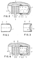
- a piston according to the invention comprises a cylinder head 1, which in this case is convex, substantially in the form of a dome, the peripheral edge of which is connected to a cylindrical skirt 2 extending over the expected length of the piston.
- the skirt 2 may optionally have a groove 3 at its end for anchoring a protective bellows.
- Piston 1-2 is produced by stamping followed by cutting excess material. The stamping can be carried out on a relatively thin metal sheet, for example with a thickness of 2.5 mm.
- a sheet thus thin is, in spite of this, in condition to resist without appreciable deformations to the great hydraulic pressure which, in operation, will be applied to the cylinder head 1, and this thanks to the dome shape of the latter, following which the stress on the cylinder head material is mainly compression, not bending.
- a piston according to the invention has a weight of approximately 150 grams, to relate to the weight typically of 350 to 400 grams of an equivalent piston, produced according to the tradional technique. This is very important because the brake caliper, in which the piston is used, is one of the unsprung components of the vehicle, for which weight reduction is of particular importance.
- a stamping operation is, in itself, less expensive than a cold extrusion operation.
- a semi-finished product can be obtained, the tolerance of which on the ribs is sufficiently reduced to allow it to be sent directly to the final grinding operation, without requiring prior machining around the skirt 2, or else its rectification in two passages.
- the groove 3 for the protective bellows when it is provided, can be obtained by using an appropriate tool in the shearing operation which follows stamping, thus avoiding turning the groove separately. All in all, the cost price of a piston according to the invention may result from the approximately 25% lower than the cost price of an equivalent piston produced according to the usual technique.
- the piston according to Figure 1 can be inserted into a pin body this of any known kind.
- this piston is used in a clamp specially designed for this purpose.
- the clamp according to Figure 2 is intended to apply to friction linings 4 and 5, carried by support plates 6 and 7 and acting on a brake disc 8, a clamping force such as to give rise to braking.
- the clamp comprises a body 9 provided on one side with console teeth 10 which act on the support plate 6.
- On the opposite side the body 9 forms a cylinder 12 in which the piston 1-2 is inserted.
- the cylinder 12 is closed at its end by a cylinder head 11. In the cylinder 12 there opens a supply connection 13 through which the pressurized liquid from the braking installation arrives at the cylinder 12.
- a gasket 14 is arranged in the cylinder 12 so as to seal with the skirt 2 of the piston.
- a bellows 15 is disposed between the cylinder 12 and the skirt 2 of the piston, to protect the coupled surfaces from contamination. This bellows 15 is anchored to the piston in correspondence with the groove 3 when the latter is provided. However, in certain cases the groove 3 can be omitted, and the bellows 15 is then simply coupled by friction with the skirt 2 of the piston.
- the special design of the clamp according to FIG. 2 consists in that the cylinder head 11 of the cylinder 12 also has a convex dome shape, substantially similar to the convex dome shape of the cylinder head 1 of the piston.
- This conformation reduces, on the one hand, the total size of the body of the clamp, and on the other hand avoids an unnecessary increase in the capacity of the cylinder 12.
- the body of the clamp also enjoys use more advantageous of the material constituting the cylinder head 11, which, in parity with the other conditions, can be produced with a thickness, and therefore a weight, more reduced.
- the piston has a cylinder head 21 in the form of a dome, which however, in this case, is concave, seen from the outside of the piston. From the cylinder head 21 extends a cylindrical skirt 22 optionally provided with a groove 23 for anchoring a protective bellows.
- the embodiment of the piston according to Figure 3 is particularly suitable for use in a normal project pliers, as shown in Figure 4.
- the parts corresponding to those of Figure 2 are indicated by reference numbers increased by 20 units, and they are not described later.
- the piston 21-22 can simply be substituted for a piston of usual manufacture in a cylinder 32 which requires no modification.
- the clamp can be specially designed for this purpose, and then the cylinder 32 can, for example, have a cylinder head 31 ′ in a concave dome, as shown by broken lines in FIG. 4.
- the present invention relates either to pistons for brake callipers, having the characteristics indicated, or to brake callipers for vehicles in which said pistons are used.
Landscapes
- Engineering & Computer Science (AREA)
- General Engineering & Computer Science (AREA)
- Mechanical Engineering (AREA)
- Braking Arrangements (AREA)
Priority Applications (1)
| Application Number | Priority Date | Filing Date | Title |
|---|---|---|---|
| AT88201548T ATE52583T1 (de) | 1987-07-28 | 1988-07-18 | Scheibenbremszange fuer ein fahrzeug. |
Applications Claiming Priority (2)
| Application Number | Priority Date | Filing Date | Title |
|---|---|---|---|
| IT8767658A IT1211245B (it) | 1987-07-28 | 1987-07-28 | Pistone in lamiera imbutita per pinze di freni a disco per veicoli |
| IT6765887 | 1987-07-28 |
Publications (2)
| Publication Number | Publication Date |
|---|---|
| EP0304103A1 true EP0304103A1 (de) | 1989-02-22 |
| EP0304103B1 EP0304103B1 (de) | 1990-05-09 |
Family
ID=11304288
Family Applications (1)
| Application Number | Title | Priority Date | Filing Date |
|---|---|---|---|
| EP88201548A Expired - Lifetime EP0304103B1 (de) | 1987-07-28 | 1988-07-18 | Scheibenbremszange für ein Fahrzeug |
Country Status (7)
| Country | Link |
|---|---|
| EP (1) | EP0304103B1 (de) |
| JP (1) | JPS6435130A (de) |
| AT (1) | ATE52583T1 (de) |
| BR (1) | BR8803721A (de) |
| DE (1) | DE3860137D1 (de) |
| ES (1) | ES2014505B3 (de) |
| IT (1) | IT1211245B (de) |
Cited By (5)
| Publication number | Priority date | Publication date | Assignee | Title |
|---|---|---|---|---|
| WO1991012445A1 (de) * | 1990-02-08 | 1991-08-22 | Alfred Teves Gmbh | Kaltverformter kolben für hydraulisch arbeitende bremse |
| DE19919574A1 (de) * | 1999-04-29 | 2000-11-30 | Lucas Ind Plc | Kolben und Verfahren zur Herstellung eines solchen |
| WO2001002745A1 (de) * | 1999-07-02 | 2001-01-11 | Continental Teves Ag & Co. Ohg | Kolben für einen hydraulischen druckraum |
| WO2014090458A1 (de) * | 2012-12-14 | 2014-06-19 | Robert Bosch Gmbh | Kolben einer kolbenpumpe einer fahrzeugbremsanlage |
| DE102017218027A1 (de) | 2017-10-10 | 2019-04-11 | Continental Teves Ag & Co. Ohg | Stahlbremskolben für eine Kraftfahrzeugteilbelagscheibenbremse |
Families Citing this family (2)
| Publication number | Priority date | Publication date | Assignee | Title |
|---|---|---|---|---|
| DE102007051456A1 (de) * | 2007-10-27 | 2009-04-30 | Continental Teves Ag & Co. Ohg | Kolben für einen Bremssattel einer Bremsscheibe |
| DE102016206027A1 (de) * | 2016-04-12 | 2017-10-12 | Bayerische Motoren Werke Aktiengesellschaft | Bremssattel einer Scheibenbremse eines Fahrzeuges |
Citations (6)
| Publication number | Priority date | Publication date | Assignee | Title |
|---|---|---|---|---|
| FR1566027A (de) * | 1967-05-22 | 1969-05-02 | ||
| FR2077739A1 (de) * | 1970-02-10 | 1971-11-05 | Thompson Tom | |
| FR2280832A1 (fr) * | 1974-08-01 | 1976-02-27 | Automotive Prod Co Ltd | Piston de frein a disque |
| DE2748499A1 (de) * | 1977-10-28 | 1979-05-03 | Teves Gmbh Alfred | Hydraulisch betaetigte fahrzeugbremse |
| FR2495252A1 (fr) * | 1980-12-03 | 1982-06-04 | Valeo | Frein a commande hydraulique muni d'un dispositif evitant l'elevation de temperature du liquide hydraulique |
| FR2549921A1 (fr) * | 1983-07-26 | 1985-02-01 | Teves Gmbh Alfred | Frein de roue actionne hydrauliquement |
-
1987
- 1987-07-28 IT IT8767658A patent/IT1211245B/it active
-
1988
- 1988-07-18 ES ES88201548T patent/ES2014505B3/es not_active Expired - Lifetime
- 1988-07-18 DE DE8888201548T patent/DE3860137D1/de not_active Revoked
- 1988-07-18 EP EP88201548A patent/EP0304103B1/de not_active Expired - Lifetime
- 1988-07-18 AT AT88201548T patent/ATE52583T1/de active
- 1988-07-27 BR BR8803721A patent/BR8803721A/pt not_active IP Right Cessation
- 1988-07-28 JP JP63189539A patent/JPS6435130A/ja active Pending
Patent Citations (6)
| Publication number | Priority date | Publication date | Assignee | Title |
|---|---|---|---|---|
| FR1566027A (de) * | 1967-05-22 | 1969-05-02 | ||
| FR2077739A1 (de) * | 1970-02-10 | 1971-11-05 | Thompson Tom | |
| FR2280832A1 (fr) * | 1974-08-01 | 1976-02-27 | Automotive Prod Co Ltd | Piston de frein a disque |
| DE2748499A1 (de) * | 1977-10-28 | 1979-05-03 | Teves Gmbh Alfred | Hydraulisch betaetigte fahrzeugbremse |
| FR2495252A1 (fr) * | 1980-12-03 | 1982-06-04 | Valeo | Frein a commande hydraulique muni d'un dispositif evitant l'elevation de temperature du liquide hydraulique |
| FR2549921A1 (fr) * | 1983-07-26 | 1985-02-01 | Teves Gmbh Alfred | Frein de roue actionne hydrauliquement |
Cited By (9)
| Publication number | Priority date | Publication date | Assignee | Title |
|---|---|---|---|---|
| WO1991012445A1 (de) * | 1990-02-08 | 1991-08-22 | Alfred Teves Gmbh | Kaltverformter kolben für hydraulisch arbeitende bremse |
| US5231916A (en) * | 1990-02-08 | 1993-08-03 | Alfred Teves Gmbh | Cold-worked piston for hydraulically operating brake |
| DE19919574A1 (de) * | 1999-04-29 | 2000-11-30 | Lucas Ind Plc | Kolben und Verfahren zur Herstellung eines solchen |
| WO2001002745A1 (de) * | 1999-07-02 | 2001-01-11 | Continental Teves Ag & Co. Ohg | Kolben für einen hydraulischen druckraum |
| US6637317B1 (en) | 1999-07-02 | 2003-10-28 | Continental Teves Ag & Co., Ohg | Piston for a hydraulic pressure chamber |
| WO2014090458A1 (de) * | 2012-12-14 | 2014-06-19 | Robert Bosch Gmbh | Kolben einer kolbenpumpe einer fahrzeugbremsanlage |
| CN104854345A (zh) * | 2012-12-14 | 2015-08-19 | 罗伯特·博世有限公司 | 车辆制动设备的活塞泵的活塞 |
| DE102017218027A1 (de) | 2017-10-10 | 2019-04-11 | Continental Teves Ag & Co. Ohg | Stahlbremskolben für eine Kraftfahrzeugteilbelagscheibenbremse |
| WO2019072623A1 (de) | 2017-10-10 | 2019-04-18 | Continental Teves Ag & Co. Ohg | Kaltumgeformter stahlbremskolben für eine kraftfahrzeugteilbelagscheibenbremse |
Also Published As
| Publication number | Publication date |
|---|---|
| DE3860137D1 (de) | 1990-06-13 |
| JPS6435130A (en) | 1989-02-06 |
| IT1211245B (it) | 1989-10-12 |
| BR8803721A (pt) | 1989-02-14 |
| IT8767658A0 (it) | 1987-07-28 |
| ATE52583T1 (de) | 1990-05-15 |
| ES2014505B3 (es) | 1990-07-16 |
| EP0304103B1 (de) | 1990-05-09 |
Similar Documents
| Publication | Publication Date | Title |
|---|---|---|
| FR2487026A1 (fr) | Frein a disque a garnitures partielles et etrier flottant, notamment pour vehicules automobiles | |
| EP0988466B1 (de) | Scheibenbremse mit vorgespanntem führungsrohr | |
| FR2785343A1 (fr) | Debrayeur central a commande hydraulique realise comme un cylindre recepteur pour un embrayage commande de separation d'un vehicule | |
| FR2812050A1 (fr) | Ensemble d'elements de friction pour la transmission d'un mouvement | |
| EP0304103A1 (de) | Scheibenbremszange für ein Fahrzeug | |
| FR2714634A1 (fr) | Roue de véhicule à voile plein, en aluminium. | |
| EP0300857B1 (de) | Zusammenbauverfahren für einen Servomotor und nach diesem Verfahren Zusammengebauter Servomotor | |
| FR2879271A1 (fr) | Couplage frottant ayant au moins un premier organe de friction comme organe complementaire | |
| FR2573700A1 (fr) | Corps de moyeu pour roue motrice de bicyclette ou similaire,et son procede de fabrication | |
| FR2524354A1 (fr) | Procede de fabrication d'element de transmission de mouvement a denture et element ainsi obtenu | |
| FR2888297A1 (fr) | Disque de frein composite et procede de fabrication | |
| EP1228320B1 (de) | Rampe mit kugeln sowie bremszylinder mit einer solchen rampe | |
| FR2956710A1 (fr) | Garniture de friction a sec, en particulier pour un embrayage de vehicule automobile | |
| JP2002507702A (ja) | 液圧的に且つ機械的に作動可能なスポット型ディスクブレーキの作動ピストン | |
| FR2557239A1 (fr) | Dispositif de guidage a broche d'un etrier coulissant de frein a disque et son procede de fabrication | |
| EP3448694A1 (de) | Kraftfahrzeugrad mit einer über geschweisste stifte verbundenen aluminiumfelge und stahlradscheibe | |
| FR2729727A1 (fr) | Piston a segment de piston pour l'etancheite | |
| EP0737819B1 (de) | Verfahren zur Herstellung einer Wellenanschlagschraube sowie Wellenanschlagschraube, insbesondere für einen Elektromotor | |
| FR2681396A1 (fr) | Piece d'etancheite statique a usages repetes. | |
| FR2591690A1 (fr) | Corps discoide, tel que disque d'embrayage pour vehicule | |
| FR2550287A1 (fr) | Dispositif d'assemblage d'un axe et d'une piece, notamment emboutie, a l'aide d'une rondelle de frettage | |
| EP0705404B1 (de) | Metallteil mit einem element das eine kugelwand hat, verfahren zur herstellung des metallteiles und kugelkupplung für eine abgasvorrichtung | |
| FR3023338A1 (fr) | Element rotatif de freinage comportant des bossages autour des percages de fixation | |
| EP0192592B1 (de) | Verfahren zum Anfügen von Endflanschen an ein Gleitlager durch Bördeln | |
| FR2560306A1 (fr) | Ecrou de securite multifonctionnel |
Legal Events
| Date | Code | Title | Description |
|---|---|---|---|
| PUAI | Public reference made under article 153(3) epc to a published international application that has entered the european phase |
Free format text: ORIGINAL CODE: 0009012 |
|
| AK | Designated contracting states |
Kind code of ref document: A1 Designated state(s): AT BE DE ES FR GB |
|
| 17P | Request for examination filed |
Effective date: 19890821 |
|
| 17Q | First examination report despatched |
Effective date: 19891019 |
|
| GRAA | (expected) grant |
Free format text: ORIGINAL CODE: 0009210 |
|
| AK | Designated contracting states |
Kind code of ref document: B1 Designated state(s): AT BE DE ES FR GB |
|
| REF | Corresponds to: |
Ref document number: 52583 Country of ref document: AT Date of ref document: 19900515 Kind code of ref document: T |
|
| REF | Corresponds to: |
Ref document number: 3860137 Country of ref document: DE Date of ref document: 19900613 |
|
| GBT | Gb: translation of ep patent filed (gb section 77(6)(a)/1977) | ||
| PLBI | Opposition filed |
Free format text: ORIGINAL CODE: 0009260 |
|
| 26 | Opposition filed |
Opponent name: LUCAS INDUSTRIES PUBLIC LIMITED COMPANY Effective date: 19910201 |
|
| PGFP | Annual fee paid to national office [announced via postgrant information from national office to epo] |
Ref country code: GB Payment date: 19930706 Year of fee payment: 6 |
|
| PGFP | Annual fee paid to national office [announced via postgrant information from national office to epo] |
Ref country code: AT Payment date: 19930713 Year of fee payment: 6 |
|
| PGFP | Annual fee paid to national office [announced via postgrant information from national office to epo] |
Ref country code: FR Payment date: 19930721 Year of fee payment: 6 |
|
| PGFP | Annual fee paid to national office [announced via postgrant information from national office to epo] |
Ref country code: DE Payment date: 19930726 Year of fee payment: 6 |
|
| PGFP | Annual fee paid to national office [announced via postgrant information from national office to epo] |
Ref country code: ES Payment date: 19930730 Year of fee payment: 6 |
|
| PGFP | Annual fee paid to national office [announced via postgrant information from national office to epo] |
Ref country code: BE Payment date: 19930901 Year of fee payment: 6 |
|
| RDAG | Patent revoked |
Free format text: ORIGINAL CODE: 0009271 |
|
| STAA | Information on the status of an ep patent application or granted ep patent |
Free format text: STATUS: PATENT REVOKED |
|
| 27W | Patent revoked |
Effective date: 19931125 |
|
| GBPR | Gb: patent revoked under art. 102 of the ep convention designating the uk as contracting state |
Free format text: 931125 |
|
| APAC | Appeal dossier modified |
Free format text: ORIGINAL CODE: EPIDOS NOAPO |
|
| APAC | Appeal dossier modified |
Free format text: ORIGINAL CODE: EPIDOS NOAPO |
|
| APAH | Appeal reference modified |
Free format text: ORIGINAL CODE: EPIDOSCREFNO |