EP0304428B1 - Dispositif de suspension monte sur un bras en porte-a-faux pour machine d'abattage de bois - Google Patents
Dispositif de suspension monte sur un bras en porte-a-faux pour machine d'abattage de boisInfo
- Publication number
- EP0304428B1 EP0304428B1 EP87903323A EP87903323A EP0304428B1 EP 0304428 B1 EP0304428 B1 EP 0304428B1 EP 87903323 A EP87903323 A EP 87903323A EP 87903323 A EP87903323 A EP 87903323A EP 0304428 B1 EP0304428 B1 EP 0304428B1
- Authority
- EP
- European Patent Office
- Prior art keywords
- harvester
- main frame
- frame
- shaft
- jib
- Prior art date
- Legal status (The legal status is an assumption and is not a legal conclusion. Google has not performed a legal analysis and makes no representation as to the accuracy of the status listed.)
- Expired
Links
- 239000000725 suspension Substances 0.000 title abstract description 26
- 230000005484 gravity Effects 0.000 claims abstract description 8
- 210000001364 upper extremity Anatomy 0.000 claims description 5
- 241001124569 Lycaenidae Species 0.000 description 2
Images


Classifications
-
- A—HUMAN NECESSITIES
- A01—AGRICULTURE; FORESTRY; ANIMAL HUSBANDRY; HUNTING; TRAPPING; FISHING
- A01G—HORTICULTURE; CULTIVATION OF VEGETABLES, FLOWERS, RICE, FRUIT, VINES, HOPS OR SEAWEED; FORESTRY; WATERING
- A01G23/00—Forestry
- A01G23/02—Transplanting, uprooting, felling or delimbing trees
- A01G23/08—Felling trees
- A01G23/083—Feller-delimbers
Definitions
- the present invention relates to timber harvesters.
- US Patent Specification No 4 537 236 describes a timber harvester suspended from the upper end of the jib by means of the upper joint.
- the harvester includes a turning motor to turn the harvester about a vertical axis of the harvester and a hydraulic cylinder, to turn the main frame of the harvester to a desired vertical or horizontal position.
- the turning motor is connected between the harvester and the jib.
- timber processors which carry out all stages of the work except felling
- felling head The purpose of this felling-head is to bring the processor to a vertical position.
- the vertical position is required in order to take hold of the tree. In practice it is sufficient if the processor is even roughly in a vertical position so that the tree can be taken hold of. Felling sawing is carried out by the cutting saw of the processor.
- the stripping and cutting of the tree takes place with the tree in a horizontal position.
- the harvester hangs freely from its felling head and in addition a so-called grab turner is located on the felling head.
- the harvester is directed round its vertical shaft by this turner.
- This felling is a suspension device, by which the harvester is made to rise to a vertical position advantageously by means of a hydraulic cylinder.
- a timber harvester arranged to be pivotally suspended from a jib, the harvester comprising an elongate main frame supporting cutters and tree engaging rollers, a sub frame pivotally connected to the main frame, a piston and cylinder arrangement for displacing said main frame relative to said sub frame between a position in which the longitudinal axis of the main frame extends substantially vertically and a position in which said longitudinal axis of the main frame extends substantially horizontally and rotation means between said sub frame and said jib to rotate said harvester about a vertical axis characterised in that said rotation means comprises universal joint means for connection to said jib, a sleeve and a shaft for interconnecting said universal joint means to said sub frame, and a drive for effecting relative rotation between said sleeve and said shaft, said shaft engaging said sleeve and being constrained for relative rotary movement, and against relative axial movement, the common axis of said sleeve and said shaft extending at an
- the timber harvester to be described achieves a short length while allowing, nevertheless, a sufficient vertical rise.
- the harvester to be described is relatively light and easy to construct.
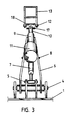
- Securing lugs attached to a main frame 1 of the harvester support two pins 4 and 5.
- the pin 4 couples a sub frame 6 of the harvester to the frame 1 in such a way that the sub frame 6 is able to turn through an angle of about 140° around the pin 4.
- the turning movement can be controlled by a cylinder 7.
- the cylinder 7 is attached to the frame 1 by the pin 5 and to the sub frame 6 by a pin 8. The attachment of the cylinder 7 thus permits the sub frame 6 to turn past the shortest position ie the lower dead centre of the cylinder 7.
- a tube or sleeve 9 is secured to the sub frame 6. Inside the tube 9 is a shaft 10, which is secured by bearing axially and radially to the tube 9. The shaft 10 is secured by a pin 17 to a cross-piece 18. The cross-piece 18 is further secured by a pin 12 in the crane jib 13. The cross-piece 18, and the pins 12 and 17 permit the frame 1 of the harvester to hang freely independently of the mutual position of the frame 1 and the sub frame 6.
- a turning motor 11 is secured to the tube 9. A second possibility would be to attach the motor to the sub frame of the suspension device.
- a cutting and felling saw 15, a pair of feeder rollers 3 and three stripping blades 2 are all secured to the frame 1. In Figure 1 any sawing action to fell a tree 14 to be felled has not yet been carried out. The centre of gravity of the harvester is located at a point 19, Figure 1.
- the piston rod of the cylinder 7 is pushed out when the sub frame 6 is close to the frame 1.
- the tube 9 guides the front edge of the frame 1 at the point 10.
- the straight line between the pins 4 and 12 does not go through the centre of gravity 19, but that the centre of gravity 19 remains closer to the tree 14.
- the angle A between the shaft 10 and the horizontal level, is significantly smaller than 90°. Up till now in previous suspension devices this corresponding angle is close to 90°.
- the size of the angle A between the shaft 10 and the horizontal can be reduced to even 45°. It would then be advantageous that the shaft 10 would be suspended from the jib 13 by a constant angular velocity joint. This is because when the turning motor 11 turns the harvester, the moment requirement varies unreasonably when using a normal universal ie a cardan joint, especially if the pins 17 and 12 cannot for structural reasons be brought close together in the direction of the shaft 10.
Landscapes
- Life Sciences & Earth Sciences (AREA)
- Biodiversity & Conservation Biology (AREA)
- Ecology (AREA)
- Forests & Forestry (AREA)
- Environmental Sciences (AREA)
- Earth Drilling (AREA)
- Placing Or Removing Of Piles Or Sheet Piles, Or Accessories Thereof (AREA)
- Harvester Elements (AREA)
- Harvesting Machines For Specific Crops (AREA)
- Turbine Rotor Nozzle Sealing (AREA)
Abstract
Claims (5)
Priority Applications (1)
| Application Number | Priority Date | Filing Date | Title |
|---|---|---|---|
| AT87903323T ATE65667T1 (de) | 1986-05-13 | 1987-05-13 | An einem ausleger montierte aufhaengevorrichtung fuer einen baumernter. |
Applications Claiming Priority (5)
| Application Number | Priority Date | Filing Date | Title |
|---|---|---|---|
| FI861985 | 1986-05-13 | ||
| FI861985A FI861985A0 (fi) | 1986-05-13 | 1986-05-13 | Upphaengningsanordning vid lastnings- och flerprocessmaskin. |
| FI870530A FI79927C (fi) | 1986-05-13 | 1987-02-10 | Upphaengningsanordning vid lastnings- och flerprocessmaskin. |
| FI870530 | 1987-02-10 | ||
| CA000603282A CA1331949C (fr) | 1986-05-13 | 1989-06-20 | Dispositif de levage a charge suspendue pour moissonneuse d'arbres |
Publications (2)
| Publication Number | Publication Date |
|---|---|
| EP0304428A1 EP0304428A1 (fr) | 1989-03-01 |
| EP0304428B1 true EP0304428B1 (fr) | 1991-07-31 |
Family
ID=27168361
Family Applications (1)
| Application Number | Title | Priority Date | Filing Date |
|---|---|---|---|
| EP87903323A Expired EP0304428B1 (fr) | 1986-05-13 | 1987-05-13 | Dispositif de suspension monte sur un bras en porte-a-faux pour machine d'abattage de bois |
Country Status (7)
| Country | Link |
|---|---|
| US (1) | US4881582A (fr) |
| EP (1) | EP0304428B1 (fr) |
| JP (1) | JPH084432B2 (fr) |
| AU (1) | AU7431887A (fr) |
| CA (1) | CA1331949C (fr) |
| RO (1) | RO104696B1 (fr) |
| WO (1) | WO1987006794A1 (fr) |
Cited By (1)
| Publication number | Priority date | Publication date | Assignee | Title |
|---|---|---|---|---|
| CN107651568A (zh) * | 2017-10-09 | 2018-02-02 | 柳州市菱丰科技有限公司 | 采伐起重机液压系统 |
Families Citing this family (17)
| Publication number | Priority date | Publication date | Assignee | Title |
|---|---|---|---|---|
| SE467233B (sv) * | 1987-06-18 | 1992-06-22 | Westlund Hans | Aggregat foer skogsavverkningsmaskin |
| FI82800C (sv) * | 1988-06-22 | 1991-04-25 | Erco Mek Ab Oy | Harvester |
| FI84128C (fi) * | 1989-05-31 | 1991-10-25 | Lauri Kalervo Ketonen | Gripharvester. |
| US5291926A (en) * | 1990-09-17 | 1994-03-08 | Assar Jansson | Cutting and sawing unit provided with a timber handling arrangement |
| US5101872A (en) * | 1991-05-02 | 1992-04-07 | Scheuren Duane L | Tree felling and stacking apparatus |
| US5441090A (en) * | 1994-02-01 | 1995-08-15 | Hill; Terrence R. | Tree cutting and wood manipulating grapple |
| WO1997017834A1 (fr) * | 1995-11-14 | 1997-05-22 | Timberjack Inc. | Tete d'abattage, d'ebranchage et de traitement d'arbres |
| US5727610A (en) * | 1996-05-02 | 1998-03-17 | Risley Enterprises Ltd. | Combined tree feller and processor |
| US5709254A (en) * | 1996-06-18 | 1998-01-20 | Argue; Fletcher | Tree harvesting apparatus |
| CA2186798C (fr) * | 1996-09-30 | 2001-02-27 | Charles D. Maclennan | Tete d'abattage inclinable |
| US6418989B1 (en) | 1998-02-19 | 2002-07-16 | Philip S. Jarman | Standing-stem timber harvesting system |
| US6167928B1 (en) * | 1998-05-26 | 2001-01-02 | Philip Jarman | Helicopter logging system |
| US7296602B1 (en) * | 2006-07-13 | 2007-11-20 | Riha Gary D | Tree processing equipment with two position pivot point for actuator ends |
| EP2405738A2 (fr) * | 2009-03-12 | 2012-01-18 | Lako Forest OY Ltd | Tête d'abattage-ébranchage et son fonctionnement |
| FI20090098A0 (fi) | 2009-03-16 | 2009-03-16 | Lauri Kalervo Ketonen | Ripustinlaite monitoimikoneessa |
| CA2776686C (fr) | 2009-10-12 | 2017-03-14 | Deere & Company | Alignement de pompes hydrauliques a detection de charge |
| FI20175988A1 (fi) * | 2017-11-06 | 2019-05-07 | Lauri Ketonen | Ripustinlaite puunkorjuukoneessa |
Family Cites Families (13)
| Publication number | Priority date | Publication date | Assignee | Title |
|---|---|---|---|---|
| US3738401A (en) * | 1970-12-03 | 1973-06-12 | Ostbergs Fabriks Ab | Apparatus for severing the root system of the tree from the trunk during the tree-felling operation |
| FI46670C (fi) * | 1972-01-13 | 1975-01-27 | Tyoetehoseura R Y | Puun katkaisulaite etenkin kasvavan puun kaatoa varten. |
| JPS5122240A (en) * | 1974-08-16 | 1976-02-21 | Eiichi Sugano | Suimenjono fujuyukaishusochi |
| SE394070B (sv) * | 1976-01-29 | 1977-06-06 | Umea Mekaniska Ab | Upphengningsanordning for fellaggregat. |
| SE419282B (sv) * | 1976-11-05 | 1981-07-27 | Kockums Ind Ab | Anordning for att kapa tred pa rot |
| SE443905B (sv) * | 1980-04-02 | 1986-03-17 | Ostbergs Fabriks Ab | Anordning vid fell- och gripaggregat |
| CA1161342A (fr) * | 1981-08-05 | 1984-01-31 | Amca International Limited/Amca Internationale Limitee | Methode et dispositif d'abattage d'arbres |
| EP0096146A1 (fr) * | 1982-06-09 | 1983-12-21 | Erik Persson | Dispositif d'abattage avec des grappins |
| FI67288C (fi) * | 1982-12-21 | 1985-03-11 | Valmet Oy | Gripskoerdare |
| GB2154846B (en) * | 1984-03-05 | 1987-04-23 | Olavi Kuusilinna | Tree harvesting device |
| SE453148B (sv) * | 1984-03-07 | 1988-01-18 | Motrac Gunnarson & Larsson Hb | Forfarande och anordning vid fellning och upparbetning av tred |
| FR2606967B1 (fr) * | 1986-11-24 | 1990-06-15 | Armef | Machine d'abattage et de faconnage d'arbres |
| JP5122240B2 (ja) | 2006-11-20 | 2013-01-16 | シーシーアイ株式会社 | ソリッドタイヤ用組成物、及びソリッドタイヤ |
-
1987
- 1987-05-13 EP EP87903323A patent/EP0304428B1/fr not_active Expired
- 1987-05-13 AU AU74318/87A patent/AU7431887A/en not_active Abandoned
- 1987-05-13 US US07/267,123 patent/US4881582A/en not_active Expired - Lifetime
- 1987-05-13 WO PCT/FI1987/000064 patent/WO1987006794A1/fr not_active Ceased
- 1987-05-13 JP JP62503083A patent/JPH084432B2/ja not_active Expired - Fee Related
-
1988
- 1988-11-11 RO RO135841A patent/RO104696B1/ro unknown
-
1989
- 1989-06-20 CA CA000603282A patent/CA1331949C/fr not_active Expired - Fee Related
Cited By (1)
| Publication number | Priority date | Publication date | Assignee | Title |
|---|---|---|---|---|
| CN107651568A (zh) * | 2017-10-09 | 2018-02-02 | 柳州市菱丰科技有限公司 | 采伐起重机液压系统 |
Also Published As
| Publication number | Publication date |
|---|---|
| CA1331949C (fr) | 1994-09-13 |
| US4881582A (en) | 1989-11-21 |
| EP0304428A1 (fr) | 1989-03-01 |
| WO1987006794A1 (fr) | 1987-11-19 |
| RO104696B1 (en) | 1994-04-28 |
| AU7431887A (en) | 1987-12-01 |
| JPH084432B2 (ja) | 1996-01-24 |
| JPH01503435A (ja) | 1989-11-22 |
Similar Documents
| Publication | Publication Date | Title |
|---|---|---|
| EP0304428B1 (fr) | Dispositif de suspension monte sur un bras en porte-a-faux pour machine d'abattage de bois | |
| US7331746B2 (en) | Apparatus for handling and racking pipes | |
| US6135175A (en) | Tree harvester provided with a rotatable worktable | |
| NO148402B (no) | Anordning ved apparat til behandling av traer. | |
| NO123202B (fr) | ||
| US3643712A (en) | Tree-shearing head | |
| US4068396A (en) | Machine for uprooting tree stumps and trees | |
| US20030019542A1 (en) | Tree felling and shaping apparatus | |
| NO138894B (no) | Skoghoestingsmaskin. | |
| US6418989B1 (en) | Standing-stem timber harvesting system | |
| US3957310A (en) | Tunnel boring machine with dual support members | |
| FI69387B (fi) | Faellaggregat | |
| ITTO970539A1 (it) | Attrezzatura di manovra per aste usate negli impianti di trivellazione | |
| US5695016A (en) | Auger telescoping hoist assembly and holding fork mechanism | |
| FI79927C (fi) | Upphaengningsanordning vid lastnings- och flerprocessmaskin. | |
| SU715064A1 (ru) | Захватно-срезающее устройство лесозаготовительной машины | |
| CA2354315C (fr) | Abatteuse et faconneuse d'arbres | |
| SU1074448A1 (ru) | Лесозаготовительна машина | |
| SU959689A1 (ru) | Захватно-срезающее устройство лесозаготовительной машины | |
| JP3075554B2 (ja) | エレクタ装置 | |
| SU722519A1 (ru) | Захватно-срезающее устройство лесозаготовительной машины | |
| SU1026715A1 (ru) | Захватно-срезающее устройство | |
| US20210362984A1 (en) | Linking device for rotatably coupling working equipment to a crane on a working machine | |
| SU1135460A1 (ru) | Захватно-срезающее устройство | |
| SU649368A1 (ru) | Захватно-срезающее устройство лесозаготовительной машины |
Legal Events
| Date | Code | Title | Description |
|---|---|---|---|
| PUAI | Public reference made under article 153(3) epc to a published international application that has entered the european phase |
Free format text: ORIGINAL CODE: 0009012 |
|
| 17P | Request for examination filed |
Effective date: 19881020 |
|
| AK | Designated contracting states |
Kind code of ref document: A1 Designated state(s): AT BE CH DE FR GB IT LI LU NL SE |
|
| 17Q | First examination report despatched |
Effective date: 19900410 |
|
| GRAA | (expected) grant |
Free format text: ORIGINAL CODE: 0009210 |
|
| AK | Designated contracting states |
Kind code of ref document: B1 Designated state(s): AT BE CH DE FR GB IT LI LU NL SE |
|
| PG25 | Lapsed in a contracting state [announced via postgrant information from national office to epo] |
Ref country code: NL Effective date: 19910731 Ref country code: LI Effective date: 19910731 Ref country code: CH Effective date: 19910731 |
|
| REF | Corresponds to: |
Ref document number: 65667 Country of ref document: AT Date of ref document: 19910815 Kind code of ref document: T |
|
| REF | Corresponds to: |
Ref document number: 3771873 Country of ref document: DE Date of ref document: 19910905 |
|
| ET | Fr: translation filed | ||
| ITF | It: translation for a ep patent filed | ||
| REG | Reference to a national code |
Ref country code: CH Ref legal event code: PL |
|
| NLV1 | Nl: lapsed or annulled due to failure to fulfill the requirements of art. 29p and 29m of the patents act | ||
| PGFP | Annual fee paid to national office [announced via postgrant information from national office to epo] |
Ref country code: LU Payment date: 19920526 Year of fee payment: 6 |
|
| PGFP | Annual fee paid to national office [announced via postgrant information from national office to epo] |
Ref country code: BE Payment date: 19920604 Year of fee payment: 6 |
|
| PLBE | No opposition filed within time limit |
Free format text: ORIGINAL CODE: 0009261 |
|
| STAA | Information on the status of an ep patent application or granted ep patent |
Free format text: STATUS: NO OPPOSITION FILED WITHIN TIME LIMIT |
|
| 26N | No opposition filed | ||
| EPTA | Lu: last paid annual fee | ||
| PG25 | Lapsed in a contracting state [announced via postgrant information from national office to epo] |
Ref country code: LU Free format text: LAPSE BECAUSE OF NON-PAYMENT OF DUE FEES Effective date: 19930513 |
|
| PGFP | Annual fee paid to national office [announced via postgrant information from national office to epo] |
Ref country code: AT Payment date: 19930526 Year of fee payment: 7 |
|
| PG25 | Lapsed in a contracting state [announced via postgrant information from national office to epo] |
Ref country code: BE Effective date: 19930531 |
|
| BERE | Be: lapsed |
Owner name: KETONEN LAURI KALERVO Effective date: 19930531 |
|
| PGFP | Annual fee paid to national office [announced via postgrant information from national office to epo] |
Ref country code: GB Payment date: 19940511 Year of fee payment: 8 |
|
| PG25 | Lapsed in a contracting state [announced via postgrant information from national office to epo] |
Ref country code: AT Effective date: 19940513 |
|
| EAL | Se: european patent in force in sweden |
Ref document number: 87903323.1 |
|
| PG25 | Lapsed in a contracting state [announced via postgrant information from national office to epo] |
Ref country code: GB Effective date: 19950513 |
|
| PGFP | Annual fee paid to national office [announced via postgrant information from national office to epo] |
Ref country code: FR Payment date: 19950531 Year of fee payment: 9 |
|
| GBPC | Gb: european patent ceased through non-payment of renewal fee |
Effective date: 19950513 |
|
| PG25 | Lapsed in a contracting state [announced via postgrant information from national office to epo] |
Ref country code: FR Effective date: 19970131 |
|
| REG | Reference to a national code |
Ref country code: FR Ref legal event code: ST |
|
| PGFP | Annual fee paid to national office [announced via postgrant information from national office to epo] |
Ref country code: DE Payment date: 20020531 Year of fee payment: 16 |
|
| PGFP | Annual fee paid to national office [announced via postgrant information from national office to epo] |
Ref country code: SE Payment date: 20030509 Year of fee payment: 17 |
|
| PG25 | Lapsed in a contracting state [announced via postgrant information from national office to epo] |
Ref country code: DE Free format text: LAPSE BECAUSE OF NON-PAYMENT OF DUE FEES Effective date: 20031202 |
|
| PG25 | Lapsed in a contracting state [announced via postgrant information from national office to epo] |
Ref country code: SE Free format text: LAPSE BECAUSE OF NON-PAYMENT OF DUE FEES Effective date: 20040514 |
|
| EUG | Se: european patent has lapsed | ||
| PG25 | Lapsed in a contracting state [announced via postgrant information from national office to epo] |
Ref country code: IT Free format text: LAPSE BECAUSE OF NON-PAYMENT OF DUE FEES;WARNING: LAPSES OF ITALIAN PATENTS WITH EFFECTIVE DATE BEFORE 2007 MAY HAVE OCCURRED AT ANY TIME BEFORE 2007. THE CORRECT EFFECTIVE DATE MAY BE DIFFERENT FROM THE ONE RECORDED. Effective date: 20050513 |