EP0304500A1 - Appareil pour orienter, alimenter et envelopper des articles - Google Patents
Appareil pour orienter, alimenter et envelopper des articles Download PDFInfo
- Publication number
- EP0304500A1 EP0304500A1 EP87112259A EP87112259A EP0304500A1 EP 0304500 A1 EP0304500 A1 EP 0304500A1 EP 87112259 A EP87112259 A EP 87112259A EP 87112259 A EP87112259 A EP 87112259A EP 0304500 A1 EP0304500 A1 EP 0304500A1
- Authority
- EP
- European Patent Office
- Prior art keywords
- articles
- rows
- wheel
- wrapping
- orienting
- Prior art date
- Legal status (The legal status is an assumption and is not a legal conclusion. Google has not performed a legal analysis and makes no representation as to the accuracy of the status listed.)
- Withdrawn
Links
- 238000002372 labelling Methods 0.000 claims abstract description 42
- 238000007599 discharging Methods 0.000 claims abstract description 31
- 230000007246 mechanism Effects 0.000 claims abstract description 30
- 230000033001 locomotion Effects 0.000 claims abstract description 15
- 238000004806 packaging method and process Methods 0.000 claims abstract description 10
- 239000000463 material Substances 0.000 claims description 21
- 230000005484 gravity Effects 0.000 claims description 6
- 238000004064 recycling Methods 0.000 claims description 6
- 230000004044 response Effects 0.000 claims description 2
- 230000009471 action Effects 0.000 description 6
- 230000000694 effects Effects 0.000 description 6
- 238000003491 array Methods 0.000 description 4
- 235000009508 confectionery Nutrition 0.000 description 4
- 238000005520 cutting process Methods 0.000 description 3
- 230000010355 oscillation Effects 0.000 description 3
- 238000007789 sealing Methods 0.000 description 3
- 238000000151 deposition Methods 0.000 description 2
- 235000013606 potato chips Nutrition 0.000 description 2
- 239000004821 Contact adhesive Substances 0.000 description 1
- 230000001070 adhesive effect Effects 0.000 description 1
- 235000019504 cigarettes Nutrition 0.000 description 1
- 238000010276 construction Methods 0.000 description 1
- 235000014510 cooky Nutrition 0.000 description 1
- 230000008878 coupling Effects 0.000 description 1
- 238000010168 coupling process Methods 0.000 description 1
- 238000005859 coupling reaction Methods 0.000 description 1
- 239000012530 fluid Substances 0.000 description 1
- 238000004519 manufacturing process Methods 0.000 description 1
- 230000003287 optical effect Effects 0.000 description 1
- 230000003534 oscillatory effect Effects 0.000 description 1
- 238000005192 partition Methods 0.000 description 1
- 230000002250 progressing effect Effects 0.000 description 1
- 238000003860 storage Methods 0.000 description 1
Images


Classifications
-
- B—PERFORMING OPERATIONS; TRANSPORTING
- B65—CONVEYING; PACKING; STORING; HANDLING THIN OR FILAMENTARY MATERIAL
- B65B—MACHINES, APPARATUS OR DEVICES FOR, OR METHODS OF, PACKAGING ARTICLES OR MATERIALS; UNPACKING
- B65B35/00—Supplying, feeding, arranging or orientating articles to be packaged
- B65B35/30—Arranging and feeding articles in groups
- B65B35/44—Arranging and feeding articles in groups by endless belts or chains
-
- B—PERFORMING OPERATIONS; TRANSPORTING
- B65—CONVEYING; PACKING; STORING; HANDLING THIN OR FILAMENTARY MATERIAL
- B65B—MACHINES, APPARATUS OR DEVICES FOR, OR METHODS OF, PACKAGING ARTICLES OR MATERIALS; UNPACKING
- B65B11/00—Wrapping, e.g. partially or wholly enclosing, articles or quantities of material, in strips, sheets or blanks, of flexible material
- B65B11/06—Wrapping articles, or quantities of material, by conveying wrapper and contents in common defined paths
- B65B11/28—Wrapping articles, or quantities of material, by conveying wrapper and contents in common defined paths in a curved path, e.g. on rotary tables or turrets
- B65B11/30—Wrapping articles, or quantities of material, by conveying wrapper and contents in common defined paths in a curved path, e.g. on rotary tables or turrets to fold the wrappers in tubular form about contents
- B65B11/32—Wrapping articles, or quantities of material, by conveying wrapper and contents in common defined paths in a curved path, e.g. on rotary tables or turrets to fold the wrappers in tubular form about contents and then to form closing folds of similar form at opposite ends of the tube
-
- B—PERFORMING OPERATIONS; TRANSPORTING
- B65—CONVEYING; PACKING; STORING; HANDLING THIN OR FILAMENTARY MATERIAL
- B65B—MACHINES, APPARATUS OR DEVICES FOR, OR METHODS OF, PACKAGING ARTICLES OR MATERIALS; UNPACKING
- B65B35/00—Supplying, feeding, arranging or orientating articles to be packaged
- B65B35/30—Arranging and feeding articles in groups
- B65B35/34—Arranging and feeding articles in groups by agitators or vibrators
-
- B—PERFORMING OPERATIONS; TRANSPORTING
- B65—CONVEYING; PACKING; STORING; HANDLING THIN OR FILAMENTARY MATERIAL
- B65G—TRANSPORT OR STORAGE DEVICES, e.g. CONVEYORS FOR LOADING OR TIPPING, SHOP CONVEYOR SYSTEMS OR PNEUMATIC TUBE CONVEYORS
- B65G47/00—Article or material-handling devices associated with conveyors; Methods employing such devices
- B65G47/02—Devices for feeding articles or materials to conveyors
- B65G47/04—Devices for feeding articles or materials to conveyors for feeding articles
- B65G47/12—Devices for feeding articles or materials to conveyors for feeding articles from disorderly-arranged article piles or from loose assemblages of articles
- B65G47/14—Devices for feeding articles or materials to conveyors for feeding articles from disorderly-arranged article piles or from loose assemblages of articles arranging or orientating the articles by mechanical or pneumatic means during feeding
- B65G47/1492—Devices for feeding articles or materials to conveyors for feeding articles from disorderly-arranged article piles or from loose assemblages of articles arranging or orientating the articles by mechanical or pneumatic means during feeding the articles being fed from a feeding conveyor
Definitions
- This invention generally relates to apparatus for orienting, feeding and wrapping articles, particularly thin wafer-like articles such as edible candy items.
- This invention is directed to providing a new and improved packaging machine which includes article orienting, feeding and wrapping apparatus which is greatly simplified and extremely efficient.
- the apparatus is particularly directed to orienting, feeding and wrapping thin wafer-like edible commodities such as small disc-shaped candies.
- An object, therefore, of the invention is to provide a new and improved apparatus of the character described.
- a packaging machine in the exemplary embodiment of the invention, includes a conveyor apparatus for orienting a plurality of disoriented wafer-like articles into single rows for wrapping.
- conveying means are provided with receptacle means for moving the articles at a feeding station in single rows extending transverse to the path of movement.
- Orienting means form a plurality of upwardly open channels extending parallel to the path of movement above the conveying means and in which the disoriented articles are deposited.
- the channels have a width greater than the thickness of one of the articles and lesser than the width of the article.
- the channels are formed in part by vertically oscillating wall means for agitating the disoriented articles and causing the articles to fall edge-wise through the channels into oriented rows in the receptacle means of the conveying means.
- the channels are formed by a plurality of spaced, alternating stationary walls and vertically oscillating walls.
- the stationary and vertically oscillating walls are in the form of elongated blades extending parallel to the path of the subjacent conveying means.
- Common drive means are provided for both the conveying means and the orienting means.
- the common drive means is operatively connected to the conveying means by a continuous drive mechanism and to the vertically oscillating walls of the orienting means by an incremental drive mechanism.
- Means in the form of a kick-back roller brush is rotatably mounted above the channels for eliminating stacking of the articles above the intended single rows.
- the stationary wall means between the vertically oscillating means, which forms the orienting channels, converge downline of the vertically oscillating wall means for closely compacting the rows of articles. Further, the downline converging stationary wall means are inclined downwardly and form part of a chute means for gravity feeding the rows of articles toward a wrapping apparatus.
- the wrapping apparatus include a first, sorting wheel having a plurality of outwardly opening pockets for receiving the rows of articles seriatum from the chute means and rotatably advancing the rows of articles through loading and discharging positions.
- Sensor means are provided adjacent the periphery of the sorting wheel between the loading and discharging positions for sensing if any given row of articles is completely filled.
- Recycle means are provided for recycling an incomplete row of articles from the sorting wheel to the conveying and orienting means along with originally supplied disoriented articles.
- the wrapping apparatus include a second, wrapping wheel having a plurality of outwardly opening pockets for receiving the rows of articles seriatum from the sorting wheel and rotatably advancing the rows of articles through loading and discharging stations.
- the loading station of the wrapping wheel is in angular alignment and adjacent to the discharging station of the sorting wheel.
- a third, labeling wheel is provided with a plurality of outwardly opening pockets for receiving the rows of articles seriatum from the wrapping wheel and rotatably advancing the rows of articles through loading and discharging stations.
- the loading station of the labeling wheel is in angular alignment and adjacent to the discharging station of the wrapping wheel.
- All three sorting, wrapping and labeling wheels are driven from the common continuous drive means of the conveying means and orienting means, with indexing means for conjointly and incrementally rotating the three wheels.
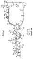
- the invention is disclosed in a packaging apparatus for orienting, feeding and wrapping articles form a loose array thereof into compact single rows which are ultimately wrapped and discharged into a shipping container.
- the apparatus is illustrated as specifically designed for handling thin wafer-like articles, such as small disc-shaped candies.
- thin wafer-like articles such as small disc-shaped candies.
- the articles to be wrapped are deposited at a feeding or orienting station, generally designated 20, whereat the disoriented articles are oriented into single rows for subsequent sorting, wrapping, labeling and packaging.
- Chute means generally designated 22, feed the single rows by gravity, with the aid of a fluidized bed, toward a sorting wheel, generally designated 24.
- the sorting wheel has a plurality of outwardly opening pockets 26 for receiving the rows of articles seriatum from chute means 22 and rotatably advancing the rows of articles through loading and discharging positions.
- Sensor means, generally designated 28 are provided adjacent the periphery of sorting wheel 24 between the loading and discharging positions for sensing if any given row of articles is completely filled. If a given row is not completely filled, the entire incomplete row is recycled by recycling means, generally designated 30, back to the feeding station defined by orienting means 20, as indicated by arrows "A".
- the sorted rows of articles then are transferred to a second, wrapping wheel, generally designated 32; from the wrapping wheel to a third, labeling wheel, generally designated 34; from labeling wheel 34 to a discharge mechanism, generally designated 36; and from discharge mechanism 36 into a container or box for shipping and handling.
- a filled container 38 is conveyed away from the machine by an appropriate conveyor 40.
- container 38 includes a central partition 42 to divide the container into the two compartments for receiving completely wrapped rows of articles 44.
- labeling wheel 34 is split at 46
- wrapping wheel 32 is split at 48
- sorting wheel 26 has gaps 50 between the ends of outwardly opening pockets 26
- chute means 22 and orienting means 20 have gaps, as at 52.
- all of the mechanisms described hereinafter on either sides of splits 46 and 48 in wheels 34 and 32, respectively, and gaps 50 and 52 in wheel 24 and chute means 22, respectively, are identical so as to provide a mechanism capable of handling two linearly oriented or side-by-side single rows of articles conjointing through the machine.
- Sorting wheel 24, wrapping wheel 32 and labeling wheel 34 all are incrementally rotated by an indexing mechanism from a continuous drive means. More particularly, referring to Figure 1A in conjunction with Figure 1, it can be seen that an indexing wheel, generally designated 54, is fixed to a drive shaft 56. for labeling wheel 34. A drive shaft 58 for wrapping wheel 34 and a drive shaft 60 for sorting wheel 32 are coupled to drive shaft 56 for labeling wheel 34 by means of gear arrangements 62 and a coupling shaft 64 so that all three drive shafts 56, 58 and 60 are conjointly and incrementally driven. A drive motor “M” is coupled through gears 66 to a first common drive shaft 68 and gears 70 to a second common drive shaft 72 for driving wheels 24, 32, and 34.
- Second common drive shaft 72 has a radially projecting arm 74 having a cam roller 76 on the distal end thereof. It can be seen best in Figure 1A that cam roller 76 is positionable within cam slots 78 in indexing wheel 46 which is fixed to drive shaft 56 for labeling wheel 34.
- art 74 and cam roller 76 will continuously rotate therewith and sequentially engage the cam roller within cam slots 78 progressively about the periphery of indexing wheel 46.
- Each rotation of drive shaft 72 and cam roller 76 will cause seriatum engagement of the roller with cam slot 78 and incrementally rotate indexing wheel 46 to incrementally rotate sorting wheel 24, wrapping wheel 32 and labeling wheel 34 through the drive shaft and gear arrangements described above.
- there are six cam slots 78 in the indexing wheel 46 which would result in a 60° rotation of the indexing wheel for each revolution of drive shaft 72 and cam roller 76, thereby effecting a 60° incrementation of sorting wheel 24, wrapping wheel 32 and labeling wheel 34.
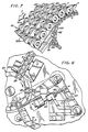
- FIG. 2 shows a somewhat schematic flow chart of the articles through the apparatus described in relation to Figure 1. It can be seen that a continuous "hopper" conveyor, generally designated 80, is provided in a vertical orientation at the lead end of the machine. This conveyor is of generally known construction and includes a plurality of hopper elements 82 for receiving articles from recycling means 30 to carry the articles back to orienting means 20, as indicated generally at 84.
- a continuous "hopper" conveyor generally designated 80
- This conveyor is of generally known construction and includes a plurality of hopper elements 82 for receiving articles from recycling means 30 to carry the articles back to orienting means 20, as indicated generally at 84.
- Figure 2 also shows that sorting wheel 24, wrapping wheel 32, labeling wheel 34 and discharge mechanism 36 all are rotatable about axes in horizontal alignments. Therefore, a discharging position, generally designated 86, for sorting wheel 24 is angularly oriented adjacent to a loading position for wrapping wheel 32. Similarly, a common position, generally designated 88, defines the discharging position for wrapping wheel 32 and the loading position for labeling wheel 34. Similarly, a common position, generally designated 90, defines a discharging position for labeling wheel 34 and a loading position for discharging mechanism 36.
- a sheet of wrapping material 92 is fed through position 86 between sorting wheel 24 and wrapping wheel 32.
- the rows of articles are pushed from outwardly opening pockets 26 in sorting wheel 24 by a pusher mechanism 94 into one of a plurality of outwardly opening pockets 96 in wrapping wheel 32.
- This effects a "U-fold" in wrapping material 92 which ultimately is completely wrapped about the rows of articles, as described hereinafter.
- a sheet of labeling material 98 is fed downwardly between wrapping wheel 32 and labeling wheel 34 at position 88.
- a pusher mechanism 100 is operatively associated with wrapping wheel 32 to push the rows of articles from the appropriately aligned outwardly opening pocket 96 into engagement with labeling material 98 and into an appropriately aligned outwardly opening pocket 102 in the periphery of labeling wheel 34. This forms a "U-fold" in the labeling material about the rows of articles for subsequent folding and sealing.
- Figures 3-5 show in greater detail the conveying means and orienting means at the lead or feeding end of the machine of this invention.
- a conveyor apparatus is provided and designed for orienting a plurality of disoriented products "P" in the form of wafer-like articles which are thin and disc-shaped. The articles are oriented into single rows for subsequent sorting, wrapping, labeling and packaging as described in relation to Figures 1-2.
- the conveyor apparatus includes conveying means, generally designated 104, having receptacle means defined by a plurality of transversely extending, parallel rods 106 for moving the articles in single rows extending transverse to the path of movement indicated by arrow "C".
- Rods 106 are connected at their opposite ends to a continuous drive chain 108 which is engaged about spaced sprockets 110.
- the chain thereby defines an upper run, generally designated 112, and a lower run, generally designated 114.
- the spacing "S" between adjacent rods 106 is less than the diameter of a single article "P". Therefore, it can be seen that the rods define a plurality of trough-like receptacle means for moving the articles in single rows extending transverse to the path of movement "C".
- Figure 5 shows that the articles actually will become oriented between every other pair of adjacent rods 106. Should one or more articles "p" become staked on top of the properly oriented single rows, a kick-back roller brush 116 is provided for eliminating such stacking problems.
- the roller brush is incrementally rotated in a reverse direction to that of the article flow path, as indicated by arrow "D" (Fig. 5). This effects a kick-back if any stacked articles, as indicated by article “P1" and arrow "E” in Figure 5.
- orienting means are provided above conveying means 104 for forming a plurality of upwardly open channels extending parallel to path of movement "C" and in which the disoriented articles are deposited for orientation.
- the channels are formed by a plurality of spaced, alternating stationary walls 120 and vertically oscillating walls 122.
- the wafer-like or disc shaped articles must be oriented in a vertical plane so as to become aligned in single rows transversely of conveying means 104. This action is best illustrated in Figure 4 where it can be seen that stationary walls 120 are spaced alternately between vertically oscillating walls 122.
- the walls are in the form of elongated blades which extend parallel to the path of movement of the subjacent conveying means formed by transverse rods 106.
- Walls 122 vertically oscillate as indicated by double-headed arrows "F" (Fig. 4).
- vertically oscillating walls 102 agitate the disoriented articles and cause the articles to fall edge-wise through the channels between adjacent pairs of stationary and oscillating walls into oriented rows in the receptacle means defined by rods 106. It can be seen that the channels defined by adjacent pairs of stationary and oscillating walls have a width greater than the thickness of the articles but less than the width of the articles.
- a common drive means is provided for both conveying means 104 and orienting means 118.
- motor “M” is shown in Figure 6 as was described in relation to Figure 1 for incrementally driving sorting wheel 24, wrapping wheel 32, labeling wheel 34 and discharging means 36.
- motor "M” is operatively connected to the conveying means and orienting means as best illustrated in Figure 6.
- the top pulley 124 of the series is fixed to a gear 128 which is conjointly in mesh with a gear 130 and a gear 132.
- Gear 130 is fixed to the right-hand sprocket 110 for driving chain 108 of conveying means 104. This is a continuous drive for continuously moving the oriented rows of articles.
- Gear 132 is fixed to roller brush 116 for continuously rotating the roller brush in the reverse direction described above as indicated by arrow "D".
- a link arm assembly In order to provide vertical oscillation of oscillating walls 122 in response to continuous drive from motor "M", a link arm assembly, generally designated 134, is provided between gear 132 and the vertically oscillating walls or blades. More. particularly, a first link arm 136 is rotatably, eccentrically fixed at one end to gear 132, as at 138.
- a second link arm 140 is connected at one end 142 to a pair of short toggle links 144.
- These toggle links are fixed to a common rod 146 which extends transversely across the apparatus and through vertically oscillating walls 122. Therefore, as gear 132 rotates, the link arms, toggle arms and rod 146 effect vertical oscillation of the walls or blades 122. The vertical oscillation is effected because a stub shaft 148 between toggle arms 144 is fixed to side frame portions 150 (Fig. 6) of the machine to define a pivot axis for the mechanism.
- Link arms 136 and 140 Adjacent ends of link arms 136 and 140 are connected to a toggle arm 152 secured to a shaft 154 which is fixed to frame portions 150 to define a pivot axis for a transversely extending blade 156 which extends across the orienting means 118.
- Blade 156 has a plurality of slots 158 through which stationary walls 120 and oscillating walls 122 freely extend.
- Rod 154 defines a pivot axis for swinging blade 154 in an oscillating manner as indicated by double-headed arrow "G" (Fig. 3). This oscillatory movement of the blade prevents bunching of articles "E” as they ride along the receptacles or troughs defined by rods 106.
- stationary walls or blades 120 extend beyond vertically oscillating walls 122 and converge, as well as slope, downwardly toward sorting wheel 124 to bring the articles into more compact rows and to gravity feed the articles to the sorting wheel.
- a plurality of extensions 120a (Fig. 7) of the walls or blades 120 slope downwardly and converge toward the sorting wheel.
- Blade extensions 120a cooperate with a bottom chute wall 162 to define chute means 22.
- several holes 161 are provided to direct air or another appropriate fluid to chute wall 162.
- Figure 8 shows that the lower end of the chute means, as at 22a, is in alignment with one of the outwardly opening pockets 26 of sorting wheel 24 when the wheel is in an incremented position. In essence, this location defines the loading positions for sorting wheel 24.
- FIG 8 also shows sensing means 28 adjacent the periphery of sorting wheel 24 between the loading position and discharging position 86 (Fig. 2) for sensing if any given row of articles is not completely filled.
- Sensing means 28 is an optical sensor of known design and feeds back to a pneumatic drive, generally designated 164, for ejecting any particular row of articles in one of the pockets 26 which is incomplete.
- Drive 164 includes a piston rod 166 connected to a bell crank, generally designated 168, pivoted to the machine frame at 170.
- the distal end of the bell crank includes an ejecting or pushing rod 172 which enters the backside of any pocket 26 which sensor 28 has indicated to contain an incomplete row of articles.
- the incomplete row is ejected or pushed into recycle trough 30 (also see Figs. 1 and 2) for recycling as described above.
- the movement of piston rod 166 and bell crank 168 is shown by the phantom and full-line positions in Figure 8.
- FIG 9 shows the action at position 86 which corresponds to the discharging position for sorting wheel 24 and labeling wheel 32.
- Pusher 94 (Fig. 2) is provided for ejecting compact rows of articles from a aligned pocket 26 in the sorting wheel into an aligned pocket 96 in wrapping wheel 32.
- This view shows more clearly how the rows of articles are pushed into engagement with wrapping material 92 to move the wrapping material with the articles into the pocket of the next wheel to form the aforementioned U-fold.
- Pusher 94 is driven through the various linkages 176.
- a first fold arm 178 moves in the direction of arrows "J" to form a first old in wrapping material 92 as shown at 180 in Figure 10.
- Cutting assembly 181 includes a stationary knife blade 183 which is contacted by rotating knife blade 185 to sever a premeasured section of wrapping material 92.
- Rotating knife blade 185 includes a plurality of "C" washers 187 thereabout which help guide the severed portion of wrapping material 92 in position for the wrapping operation.
- Rotating knife blade 185 is also driven in timed relation through various linkages, including an eliptical gear (not shown) which causes the rotating blade speed to vary during its cutting operation. Specifically, rotating blade 185 is driven slowly away from stationary blade 183 and is driven more quickly in a counterclockwise direction toward the knife blade. This imparts a clean cut to wrapping material 92, while tending to prevent adherence of wrapping material to either knife blade.
- Figures 11 and 12 show the action of a movable fold blade 182 (Fig. 11) and a stationary fold and overlap blade 184 (Fig. 12).
- Fold blade 182 moves downwardly to fold a first flap of the severed wrapping material 92.
- fold and overlap blade 184 provides the fold for a second flap and causes the ends of the wrapping material to overlap, as at 186 in Figure 12.
- Appropriate contact adhesive effects the seal along a linear seam of the row of articles in the respective pocket 96 of wrapping wheel 32.
- Figure 13 shows position 88 (Fig. 2) between wrapping wheel 32 and labeling wheel 34 which defines the discharging position for the wrapping wheel and the loading position for the labeling wheel.
- second and third end folds must be performed as indicated at 188 in Figure 14 and 190 in Figure 15. More particularly, it can be seen that a fold arm 192 (Fig. 13) is moved in the direction arrow "K" to effect second end fold 188.
- Fold arm 192 is actuated by appropriate link arms 193 operatively associated with the drive means of the machine when the rows of articles are at the momentary incremented position shown in Figure 13.
- third fold 190 is effected by a stationary fold blade 194. Therefore, by the time the rows of articles reach the discharging position of wrapping wheel 32, the linear edges of the wrapping material have been overlapped and three folds have been effected at the ends of the rows of articles.
- pusher 100 (Fig. 2) is provided for ejecting the wrapped rows of articles from wrapping wheel 32 and moving the rows into engagement with labeling material 98 to effect a U-fold about the wrapped rolls.
- Pusher 100 is similar to pusher 94 (Fig. 9) except that pusher 100 can be connected to and operatively movable at the same time as fold arm 192, as shown in Figure 13.
- Figures 16 and 17 show the action of another doctor 198 and fold and overlap blade 200 for severing labeling material 98 from a supply thereof and overlapping and sealing the linear edges thereof.
- material 98 is for labeling purposes, rather than wrapping and sealing, a tubular sheaf is formed about the previously wrapped rows of articles and no end folds are necessary.
- Figure 18 shows the discharging position 90 (Fig 2) of the wrapped and label rows of articles from labeling wheel 34 to discharging mechanism 36 which moves the wrapped and labeled rows of articles into container 38.
- a pusher arm 202 is provided for moving the wrapped and labeled articles from the properly positioned pocket 102 of the labeling wheel onto discharge mechanism 36.
- discharge mechanism 36 includes a paddle-like member 204 pivotally mounted on the machine at 206 for incremental rotation in the direction of arrow "L". This effects depositing of the completely wrapped and labeled articles into container 38.
Landscapes
- Engineering & Computer Science (AREA)
- Mechanical Engineering (AREA)
Priority Applications (2)
| Application Number | Priority Date | Filing Date | Title |
|---|---|---|---|
| US06/876,172 US4688373A (en) | 1986-06-19 | 1986-06-19 | Article orienting, feeding and wrapping apparatus |
| EP87112259A EP0304500A1 (fr) | 1987-08-24 | 1987-08-24 | Appareil pour orienter, alimenter et envelopper des articles |
Applications Claiming Priority (1)
| Application Number | Priority Date | Filing Date | Title |
|---|---|---|---|
| EP87112259A EP0304500A1 (fr) | 1987-08-24 | 1987-08-24 | Appareil pour orienter, alimenter et envelopper des articles |
Publications (1)
| Publication Number | Publication Date |
|---|---|
| EP0304500A1 true EP0304500A1 (fr) | 1989-03-01 |
Family
ID=8197220
Family Applications (1)
| Application Number | Title | Priority Date | Filing Date |
|---|---|---|---|
| EP87112259A Withdrawn EP0304500A1 (fr) | 1986-06-19 | 1987-08-24 | Appareil pour orienter, alimenter et envelopper des articles |
Country Status (1)
| Country | Link |
|---|---|
| EP (1) | EP0304500A1 (fr) |
Cited By (5)
| Publication number | Priority date | Publication date | Assignee | Title |
|---|---|---|---|---|
| CN108860762A (zh) * | 2018-07-20 | 2018-11-23 | 浙江丸三洗涤智能设备有限公司 | 一种平面自动包装机 |
| CN109823603A (zh) * | 2019-03-28 | 2019-05-31 | 漯河恒丰机械制造科技有限公司 | 一种食品摆序机 |
| CN109850399A (zh) * | 2018-12-22 | 2019-06-07 | 山东科技大学 | 一种半自动医用棉签出签机及其使用方法 |
| CN111099319A (zh) * | 2019-12-25 | 2020-05-05 | 西安邮电大学 | 运用于糖果包装的巧克力糖衣涂覆装置 |
| EP4269293A1 (fr) * | 2022-04-25 | 2023-11-01 | Theegarten-Pactec GmbH & Co. KG | Procédé et dispositif de séparation et de traitement de produits de petite taille |
Citations (3)
| Publication number | Priority date | Publication date | Assignee | Title |
|---|---|---|---|---|
| CH149284A (de) * | 1930-09-15 | 1931-08-31 | Schweiz Ind Ges | Verfahren und Maschine zum reihenweisen Ordnen leicht aneinander haftender Tabletten von geringer Festigkeit, insbesondere von Fruchtbonbons. |
| US2702111A (en) * | 1951-01-25 | 1955-02-15 | Heide Inc Henry | Selective positioning, stacking, and feeding machine |
| US2983374A (en) * | 1956-07-05 | 1961-05-09 | Crompton & Knowles Packaging C | Tablet feeding mechanism |
-
1987
- 1987-08-24 EP EP87112259A patent/EP0304500A1/fr not_active Withdrawn
Patent Citations (3)
| Publication number | Priority date | Publication date | Assignee | Title |
|---|---|---|---|---|
| CH149284A (de) * | 1930-09-15 | 1931-08-31 | Schweiz Ind Ges | Verfahren und Maschine zum reihenweisen Ordnen leicht aneinander haftender Tabletten von geringer Festigkeit, insbesondere von Fruchtbonbons. |
| US2702111A (en) * | 1951-01-25 | 1955-02-15 | Heide Inc Henry | Selective positioning, stacking, and feeding machine |
| US2983374A (en) * | 1956-07-05 | 1961-05-09 | Crompton & Knowles Packaging C | Tablet feeding mechanism |
Cited By (7)
| Publication number | Priority date | Publication date | Assignee | Title |
|---|---|---|---|---|
| CN108860762A (zh) * | 2018-07-20 | 2018-11-23 | 浙江丸三洗涤智能设备有限公司 | 一种平面自动包装机 |
| CN108860762B (zh) * | 2018-07-20 | 2023-09-26 | 丸三浩联科技(浙江)有限公司 | 一种平面自动包装机 |
| CN109850399A (zh) * | 2018-12-22 | 2019-06-07 | 山东科技大学 | 一种半自动医用棉签出签机及其使用方法 |
| CN109850399B (zh) * | 2018-12-22 | 2023-08-22 | 山东科技大学 | 一种半自动医用棉签出签机及其使用方法 |
| CN109823603A (zh) * | 2019-03-28 | 2019-05-31 | 漯河恒丰机械制造科技有限公司 | 一种食品摆序机 |
| CN111099319A (zh) * | 2019-12-25 | 2020-05-05 | 西安邮电大学 | 运用于糖果包装的巧克力糖衣涂覆装置 |
| EP4269293A1 (fr) * | 2022-04-25 | 2023-11-01 | Theegarten-Pactec GmbH & Co. KG | Procédé et dispositif de séparation et de traitement de produits de petite taille |
Similar Documents
| Publication | Publication Date | Title |
|---|---|---|
| US3988875A (en) | Apparatus for producing and packaging food chips | |
| CA2272827C (fr) | Appareil convoyeur pour introduction dans des contenants de produits repartis en groupes | |
| US5425215A (en) | Apparatus for packaging loose leaf material | |
| KR100222416B1 (ko) | 물품이송장치 | |
| SU856373A3 (ru) | Автоматическа упаковочна лини | |
| US7559186B2 (en) | Wrap around carton packaging machine | |
| US4043442A (en) | Transfer mechanism | |
| US4999970A (en) | Apparatus for making cigarette packs and the like | |
| JPH0210007B2 (fr) | ||
| KR20150014275A (ko) | 다수의 병 포장물을 일괄포장하는 랩 어라운드 포장기 | |
| US4909020A (en) | Process and apparatus for wrapping, especially cigarette packs | |
| JPH085462B2 (ja) | 包装材料用空包の供給及び成型装置 | |
| JPH01240409A (ja) | カラーを有するヒンジ蓋付き・煙草パッケージの製造装置 | |
| US4688373A (en) | Article orienting, feeding and wrapping apparatus | |
| JP3615896B2 (ja) | 2段積み包装装置,カートンピックアップ装置及びカートン箱型化装置 | |
| EP0304500A1 (fr) | Appareil pour orienter, alimenter et envelopper des articles | |
| US4134502A (en) | Apparatus for forming groups made up by a plurality of side-by-side positioned piles of parallelepipedon shaped articles | |
| US3911643A (en) | Cigarette packing machine | |
| CS210612B2 (en) | Device for forming of groups of products | |
| EP0553625B1 (fr) | Appareil de pliage à ergots dans un dispositif d'emballage | |
| EP0034734A1 (fr) | Procédé et appareil pour découper et transporter des articles emballés à partir d'une bande | |
| US5862648A (en) | Partition feeder | |
| US4056200A (en) | High speed stacker | |
| US3553925A (en) | Cigarette packer | |
| EP0854085A1 (fr) | Dispositif rotatif pour alimenter des articles en forme de tiges |
Legal Events
| Date | Code | Title | Description |
|---|---|---|---|
| PUAI | Public reference made under article 153(3) epc to a published international application that has entered the european phase |
Free format text: ORIGINAL CODE: 0009012 |
|
| AK | Designated contracting states |
Kind code of ref document: A1 Designated state(s): CH DE ES FR GB IT LI SE |
|
| STAA | Information on the status of an ep patent application or granted ep patent |
Free format text: STATUS: THE APPLICATION IS DEEMED TO BE WITHDRAWN |
|
| 18D | Application deemed to be withdrawn |
Effective date: 19890904 |
|
| RIN1 | Information on inventor provided before grant (corrected) |
Inventor name: PARLOUR, NOEL S. |