EP0304528A2 - Bürstenanordnung in einem elektrischen Motor - Google Patents
Bürstenanordnung in einem elektrischen Motor Download PDFInfo
- Publication number
- EP0304528A2 EP0304528A2 EP87311049A EP87311049A EP0304528A2 EP 0304528 A2 EP0304528 A2 EP 0304528A2 EP 87311049 A EP87311049 A EP 87311049A EP 87311049 A EP87311049 A EP 87311049A EP 0304528 A2 EP0304528 A2 EP 0304528A2
- Authority
- EP
- European Patent Office
- Prior art keywords
- brush
- cage
- leaf spring
- electric motor
- wall
- Prior art date
- Legal status (The legal status is an assumption and is not a legal conclusion. Google has not performed a legal analysis and makes no representation as to the accuracy of the status listed.)
- Withdrawn
Links
Images

Classifications
-
- H—ELECTRICITY
- H02—GENERATION; CONVERSION OR DISTRIBUTION OF ELECTRIC POWER
- H02K—DYNAMO-ELECTRIC MACHINES
- H02K5/00—Casings; Enclosures; Supports
- H02K5/04—Casings or enclosures characterised by the shape, form or construction thereof
- H02K5/14—Means for supporting or protecting brushes or brush holders
- H02K5/143—Means for supporting or protecting brushes or brush holders for cooperation with commutators
- H02K5/148—Slidably supported brushes
-
- H—ELECTRICITY
- H01—ELECTRIC ELEMENTS
- H01R—ELECTRICALLY-CONDUCTIVE CONNECTIONS; STRUCTURAL ASSOCIATIONS OF A PLURALITY OF MUTUALLY-INSULATED ELECTRICAL CONNECTING ELEMENTS; COUPLING DEVICES; CURRENT COLLECTORS
- H01R39/00—Rotary current collectors, distributors or interrupters
- H01R39/02—Details for dynamo electric machines
- H01R39/38—Brush holders
- H01R39/381—Brush holders characterised by the application of pressure to brush
Definitions
- the present invention relates to a brush assembly for an electric motor particularly a fractional horse power PMDC (permanent magnet direct current) motor.
- PMDC permanent magnet direct current
- PMDC motors utilise a brush assembly in which a brush is loosely held in a tubular metal cage.
- the brush is urged out of one end of the cage against a commutator by a torsion spring.
- the torsion spring is mounted on the cage.
- the contact between the torsion spring and the brush offers a low resistance path for the current, when compared to that between the cage and the brush. This is probably due to there being a firm, pressure contact between the spring and the brush.
- the passage of current through the spring heats it up, over a period of time this anneals the spring and so weakens it.
- the present invention provides an electric motor having a brush assembly electrically connected to a terminal of the motor, the brush assembly comprising a brush slidably mounted in a generally rectangular cross-section tubular cage open at at least one end, first means for urging the brush through the open end of the cage onto a commutator of the motor and second means for urging the brush against a wall of the cage to reduce brush chatter, wherein said second means comprises a resilient electrically conducting leaf spring which is in electrical contact with the terminal and, which is mounted at one end and is configured to bear at its other end against the brush to bias it against the opposite wall of the cage, the leaf spring making at least line contact with the brush.
- the leaf spring is mounted at said one end by attachment to a cage wall.
- the leaf spring is attached at said one end or is integral with the terminal.
- the leaf spring urges the brush in the axial direction of the commutator. This will help reduce brush chatter when the motor rotates in either direction.
- the leaf spring comprises a central, generally planar portion, a first end portion at one end of the central portion, the first end portion being attached to the cage wall, and a second end portion at the other end of the central portion, the junction region between the second end portion and the central portion contacting the brush.
- the leaf spring may comprise a first leg by which the spring is attached to the terminal and a second leg obliquely inclined relative to the first leg and bearing against the brush.
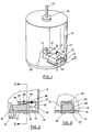
- Figure 1 shows a fractional horsepower permanent magnet direct current motor of the type manufactured by the applicants and marketed under catalogue No. HF260G, but incorporating a modified caged brush assembly in accordance with the invention.
- a steel motor casing 9 carries an electrically insulating end cap 10, typically of plastics.
- a motor shaft 15 is journalled in bearings 16 in an end of the casing 9 and in the end cap 10 (not shown).
- Shaft 15 carries a wound armature (not shown) which is supplied with current via a commutator 14 and brush assembly 11.
- the brush assembly 11 comprises a metal base plate 19 forming a first wall of the brush cage 17, and a channel shaped metal portion having a top wall 20 parallel to the base plate 19 and side walls 21, 22.
- a brush 12 is loosely mounted in the cage 17 and is urged against commutator 14 by a torsion spring 13 which is mounted on the base plate 19 and which projects through a slot 18 in side wall 22.
- walls 21, 22 each have a tab 25 which projects through an aperture in the base plate 19 and the end cap 10, the tabs being bent over to hold the cage on the end cap.
- One of the tabs may also form a terminal for the supply of electricity to the cage.
- a leaf spring 26 of Beryllium Copper alloy has a first end portion 27 which is riveted 28 to the top wall 17.
- the leaf spring 26 has a central portion 29 biassed away from the top wall 20 and an up turned second end portion 30. The spring bears against the brush 12 at the junction 31 between the central portion 29 and the second end portion 30 to urge it against the base plate 19.
- Leaf spring 26 reduces the noise caused by brush chatter when the motor is rotated in either direction,the brush being biassed axially of the commutator, and also provides electrical and positive contact between the brush 12 and the cage 17, by means of the rivets 28 and the extended contact area 31, so that the leaf spring provides a low resistance electrical path between the cage and the brush.
- the leaf spring is of greater cross-sectional area than the torsion spring 13 and so there will be less electrical heating of the leaf spring, reducing any annealing effect.
- the brush assembly 41 shown in Figures 4 and 5 is similar to the brush assembly 11 of Figures 1 to 3 and comprises a metal base plate 42 forming a first wall of the brush cage 43, and a channel shaped metal portion having a top wall 44 parallel to the base plate 42, and side walls 45 and 46.
- the side walls 45 and 46 have respective flanges 45 a and 46 a which are fixed to the insulating end cap 47 so as to locate the channel shaped metal portion in position.
- Flange 46a and base plate 42 are fixed to the end cap 47 by a hollow rivet 53, whilst flange 45a encircles a post 54 on the end cap 47.
- a metal sleeve 55 is a force fit over the post 54 and holds the flange 45a against the end cap 47, through the intermediary of an insulating washer 56.
- the metal base plate 42 is formed with an integral tab 48 which is generally at right angles to the plate 42 and which projects through a slot 49 in the insulating end cap 47. This tab 48 provides a terminal for the motor.
- a leaf spring 50 is provided for urging the brush 12 against the inner face of top wall 44 of the brush assembly 41.
- This spring 50 comprises two obliquely inclined legs 51 and 52 the former of which is attached in electrical connection (e.g. by solder or the like) to a face of tab 48 so as to secure spring 50 in position.
- the end of leg 51 adjacent its junction with leg 52 locates in slot 49 in the end cap 47, leg 52 extending upwardly into the brush cage 43 as seen in Figure 4 to urge brush 12 against the top wall 44.
- the spring 50 serves to reduce noise caused by brush chatter as well as reduce the heating of torsion spring 13 in the same way as the spring 26 in the embodiment of Figures 1 to 3.
- the brush cage may be of plastics and may be integrally moulded as part of the end cap of the assembly.
- the arm 51 of the leaf spring 50 may form the motor terminal, but it is preferred to use different materials to perform these different tasks.
- the leaf spring 50 may be riveted to a terminal, the assembly being gripped in a slot in the end cap to hold the spring and terminal in position.
Landscapes
- Engineering & Computer Science (AREA)
- Power Engineering (AREA)
- Motor Or Generator Current Collectors (AREA)
- Motor Or Generator Frames (AREA)
Applications Claiming Priority (2)
| Application Number | Priority Date | Filing Date | Title |
|---|---|---|---|
| GB08720346A GB2195835A (en) | 1986-09-08 | 1987-08-28 | Anti-chatter brush assembly in an electric motor |
| GB8720346 | 1987-08-28 |
Publications (2)
| Publication Number | Publication Date |
|---|---|
| EP0304528A2 true EP0304528A2 (de) | 1989-03-01 |
| EP0304528A3 EP0304528A3 (de) | 1989-07-26 |
Family
ID=10622975
Family Applications (1)
| Application Number | Title | Priority Date | Filing Date |
|---|---|---|---|
| EP87311049A Withdrawn EP0304528A3 (de) | 1987-08-28 | 1987-12-15 | Bürstenanordnung in einem elektrischen Motor |
Country Status (1)
| Country | Link |
|---|---|
| EP (1) | EP0304528A3 (de) |
Cited By (5)
| Publication number | Priority date | Publication date | Assignee | Title |
|---|---|---|---|---|
| WO1996027925A1 (en) * | 1995-03-07 | 1996-09-12 | The Whitaker Corporation | Electrical motor assembly and contact for use therewith |
| WO2005008847A1 (de) * | 2003-07-16 | 2005-01-27 | Robert Bosch Gmbh | Bürstenanordnung für eine elektrische maschine |
| US6856066B2 (en) * | 2002-07-19 | 2005-02-15 | Jeco Co., Ltd. | Brush device |
| WO2018019725A1 (de) * | 2016-07-26 | 2018-02-01 | Schunk Hoffmann Carbon Technology Ag | Ableiteinrichtung zur ableitung elektrischer störungen |
| CN111293556A (zh) * | 2018-12-06 | 2020-06-16 | 西门子歌美飒可再生能源公司 | 电刷组件 |
Family Cites Families (6)
| Publication number | Priority date | Publication date | Assignee | Title |
|---|---|---|---|---|
| US3526797A (en) * | 1969-09-29 | 1970-09-01 | Gen Electric | Stabilizing spring assembly for brushholder |
| JPS5746648A (en) * | 1980-08-29 | 1982-03-17 | Mitsubishi Electric Corp | Brush holding device |
| JPS58179144A (ja) * | 1982-04-09 | 1983-10-20 | Hitachi Ltd | 小形回転電機用ブラシホルダ |
| DE8411655U1 (de) * | 1984-04-13 | 1984-08-02 | Vorwerk & Co Interholding Gmbh, 5600 Wuppertal | Bürstenhalter für Kohlebürsten an Elektromotoren |
| EP0175992B1 (de) * | 1984-09-19 | 1988-05-11 | Siemens Aktiengesellschaft | Verfahren zur Herstellung einer Bürstenhalterung einer Kommutatormaschine |
| GB2189653A (en) * | 1986-04-07 | 1987-10-28 | Johnson Electric Ind Mfg | Anti:chatter brush assembly |
-
1987
- 1987-12-15 EP EP87311049A patent/EP0304528A3/de not_active Withdrawn
Cited By (13)
| Publication number | Priority date | Publication date | Assignee | Title |
|---|---|---|---|---|
| WO1996027925A1 (en) * | 1995-03-07 | 1996-09-12 | The Whitaker Corporation | Electrical motor assembly and contact for use therewith |
| US5915988A (en) * | 1995-03-07 | 1999-06-29 | The Whitaker Corporation | Contact for electrical motors |
| CN1063290C (zh) * | 1995-03-07 | 2001-03-14 | 惠特克公司 | 电机的组装方法及该电机上的接触器 |
| US6856066B2 (en) * | 2002-07-19 | 2005-02-15 | Jeco Co., Ltd. | Brush device |
| WO2005008847A1 (de) * | 2003-07-16 | 2005-01-27 | Robert Bosch Gmbh | Bürstenanordnung für eine elektrische maschine |
| US7420311B2 (en) | 2003-07-16 | 2008-09-02 | Robert Bosch Gmbh | Brush arrangement for an electric machine |
| WO2018019725A1 (de) * | 2016-07-26 | 2018-02-01 | Schunk Hoffmann Carbon Technology Ag | Ableiteinrichtung zur ableitung elektrischer störungen |
| CN109565227A (zh) * | 2016-07-26 | 2019-04-02 | 申克碳科技有限公司 | 用于释放电干扰的释放装置 |
| CN109565227B (zh) * | 2016-07-26 | 2021-05-25 | 申克碳科技有限公司 | 用于释放电干扰的释放装置 |
| US11121608B2 (en) | 2016-07-26 | 2021-09-14 | Schunk Carbon Technology Gmbh | Discharging device for discharging electrical interference |
| CN111293556A (zh) * | 2018-12-06 | 2020-06-16 | 西门子歌美飒可再生能源公司 | 电刷组件 |
| US11187209B2 (en) * | 2018-12-06 | 2021-11-30 | Siemens Gamesa Renewable Energy A/S | Brush assembly |
| CN111293556B (zh) * | 2018-12-06 | 2022-05-13 | 西门子歌美飒可再生能源公司 | 电刷组件 |
Also Published As
| Publication number | Publication date |
|---|---|
| EP0304528A3 (de) | 1989-07-26 |
Similar Documents
| Publication | Publication Date | Title |
|---|---|---|
| JP4986412B2 (ja) | ブラシアセンブリ | |
| EP0767525B1 (de) | Bürstenhalter für elektrischen Motor | |
| EP0638982B1 (de) | Miniaturmotor | |
| JPH0127414Y2 (de) | ||
| US6011341A (en) | DC motor having a brush holder provided with a terminal projection portion | |
| US2629061A (en) | Electric motor | |
| EP0645872B1 (de) | Kleinmotor | |
| US5382852A (en) | Miniature motor | |
| US5281876A (en) | Miniature motor | |
| JPS63167371U (de) | ||
| EP1538729B1 (de) | Bürstenhalter für einen elektrischen Motor | |
| EP1124306B1 (de) | Bürstenhalteranordnung | |
| US5012149A (en) | Assembled commutator for an electric motor | |
| US5434460A (en) | Miniature motor | |
| GB2195835A (en) | Anti-chatter brush assembly in an electric motor | |
| US4085346A (en) | Brush device for miniature electric motor | |
| US4983872A (en) | Brush gear for a permanent magnet motor | |
| US6198192B1 (en) | Brush-holding device | |
| GB2232011A (en) | Terminal adapter in an electric motor | |
| EP0650243A1 (de) | Bürstenanordnung | |
| EP0260040A1 (de) | Entstörung in Elektromotoren | |
| GB2207292A (en) | Electric motor | |
| JP3675040B2 (ja) | 小型振動コアレスモータ | |
| JPS6377457U (de) | ||
| EP0304528A3 (de) | Bürstenanordnung in einem elektrischen Motor |
Legal Events
| Date | Code | Title | Description |
|---|---|---|---|
| PUAI | Public reference made under article 153(3) epc to a published international application that has entered the european phase |
Free format text: ORIGINAL CODE: 0009012 |
|
| AK | Designated contracting states |
Kind code of ref document: A2 Designated state(s): DE FR IT |
|
| PUAL | Search report despatched |
Free format text: ORIGINAL CODE: 0009013 |
|
| AK | Designated contracting states |
Kind code of ref document: A3 Designated state(s): DE FR IT |
|
| STAA | Information on the status of an ep patent application or granted ep patent |
Free format text: STATUS: THE APPLICATION IS DEEMED TO BE WITHDRAWN |
|
| 18D | Application deemed to be withdrawn |
Effective date: 19900129 |
|
| RIN1 | Information on inventor provided before grant (corrected) |
Inventor name: STROBL, GEORG |