EP0304532B1 - Verbrennungsanlage mit mindestens einer rohrförmigen Verbrennungskammer - Google Patents
Verbrennungsanlage mit mindestens einer rohrförmigen Verbrennungskammer Download PDFInfo
- Publication number
- EP0304532B1 EP0304532B1 EP19870850246 EP87850246A EP0304532B1 EP 0304532 B1 EP0304532 B1 EP 0304532B1 EP 19870850246 EP19870850246 EP 19870850246 EP 87850246 A EP87850246 A EP 87850246A EP 0304532 B1 EP0304532 B1 EP 0304532B1
- Authority
- EP
- European Patent Office
- Prior art keywords
- combustion
- burner
- tubular furnace
- chamber
- combustion chamber
- Prior art date
- Legal status (The legal status is an assumption and is not a legal conclusion. Google has not performed a legal analysis and makes no representation as to the accuracy of the status listed.)
- Expired
Links
- 238000002485 combustion reaction Methods 0.000 title claims description 51
- 239000007789 gas Substances 0.000 claims description 43
- 239000000567 combustion gas Substances 0.000 claims description 9
- 239000012530 fluid Substances 0.000 claims description 7
- 239000000779 smoke Substances 0.000 claims description 6
- XLYOFNOQVPJJNP-UHFFFAOYSA-N water Substances O XLYOFNOQVPJJNP-UHFFFAOYSA-N 0.000 claims description 6
- 230000000063 preceeding effect Effects 0.000 claims 2
- 239000000446 fuel Substances 0.000 description 7
- 239000002245 particle Substances 0.000 description 5
- 239000000047 product Substances 0.000 description 3
- 239000007787 solid Substances 0.000 description 3
- 238000001816 cooling Methods 0.000 description 2
- 230000006378 damage Effects 0.000 description 2
- 238000010438 heat treatment Methods 0.000 description 2
- QVGXLLKOCUKJST-UHFFFAOYSA-N atomic oxygen Chemical compound [O] QVGXLLKOCUKJST-UHFFFAOYSA-N 0.000 description 1
- 239000006227 byproduct Substances 0.000 description 1
- 229920002678 cellulose Polymers 0.000 description 1
- 239000001913 cellulose Substances 0.000 description 1
- 230000000694 effects Effects 0.000 description 1
- 239000008236 heating water Substances 0.000 description 1
- 229930195733 hydrocarbon Natural products 0.000 description 1
- 150000002430 hydrocarbons Chemical class 0.000 description 1
- 238000009413 insulation Methods 0.000 description 1
- 238000004519 manufacturing process Methods 0.000 description 1
- 238000012986 modification Methods 0.000 description 1
- 230000004048 modification Effects 0.000 description 1
- 229910052760 oxygen Inorganic materials 0.000 description 1
- 239000001301 oxygen Substances 0.000 description 1
- 239000002904 solvent Substances 0.000 description 1
- 239000004071 soot Substances 0.000 description 1
- 239000007921 spray Substances 0.000 description 1
Images


Classifications
-
- F—MECHANICAL ENGINEERING; LIGHTING; HEATING; WEAPONS; BLASTING
- F23—COMBUSTION APPARATUS; COMBUSTION PROCESSES
- F23C—METHODS OR APPARATUS FOR COMBUSTION USING FLUID FUEL OR SOLID FUEL SUSPENDED IN A CARRIER GAS OR AIR
- F23C6/00—Combustion apparatus characterised by the combination of two or more combustion chambers or combustion zones, e.g. for staged combustion
-
- F—MECHANICAL ENGINEERING; LIGHTING; HEATING; WEAPONS; BLASTING
- F23—COMBUSTION APPARATUS; COMBUSTION PROCESSES
- F23G—CREMATION FURNACES; CONSUMING WASTE PRODUCTS BY COMBUSTION
- F23G5/00—Incineration of waste; Incinerator constructions; Details, accessories or control therefor
- F23G5/44—Details; Accessories
- F23G5/46—Recuperation of heat
-
- F—MECHANICAL ENGINEERING; LIGHTING; HEATING; WEAPONS; BLASTING
- F23—COMBUSTION APPARATUS; COMBUSTION PROCESSES
- F23G—CREMATION FURNACES; CONSUMING WASTE PRODUCTS BY COMBUSTION
- F23G7/00—Incinerators or other apparatus for consuming industrial waste, e.g. chemicals
- F23G7/06—Incinerators or other apparatus for consuming industrial waste, e.g. chemicals of waste gases or noxious gases, e.g. exhaust gases
- F23G7/061—Incinerators or other apparatus for consuming industrial waste, e.g. chemicals of waste gases or noxious gases, e.g. exhaust gases with supplementary heating
- F23G7/065—Incinerators or other apparatus for consuming industrial waste, e.g. chemicals of waste gases or noxious gases, e.g. exhaust gases with supplementary heating using gaseous or liquid fuel
-
- F—MECHANICAL ENGINEERING; LIGHTING; HEATING; WEAPONS; BLASTING
- F23—COMBUSTION APPARATUS; COMBUSTION PROCESSES
- F23G—CREMATION FURNACES; CONSUMING WASTE PRODUCTS BY COMBUSTION
- F23G7/00—Incinerators or other apparatus for consuming industrial waste, e.g. chemicals
- F23G7/06—Incinerators or other apparatus for consuming industrial waste, e.g. chemicals of waste gases or noxious gases, e.g. exhaust gases
- F23G7/061—Incinerators or other apparatus for consuming industrial waste, e.g. chemicals of waste gases or noxious gases, e.g. exhaust gases with supplementary heating
- F23G7/065—Incinerators or other apparatus for consuming industrial waste, e.g. chemicals of waste gases or noxious gases, e.g. exhaust gases with supplementary heating using gaseous or liquid fuel
- F23G7/066—Incinerators or other apparatus for consuming industrial waste, e.g. chemicals of waste gases or noxious gases, e.g. exhaust gases with supplementary heating using gaseous or liquid fuel preheating the waste gas by the heat of the combustion, e.g. recuperation type incinerator
-
- F—MECHANICAL ENGINEERING; LIGHTING; HEATING; WEAPONS; BLASTING
- F23—COMBUSTION APPARATUS; COMBUSTION PROCESSES
- F23J—REMOVAL OR TREATMENT OF COMBUSTION PRODUCTS OR COMBUSTION RESIDUES; FLUES
- F23J15/00—Arrangements of devices for treating smoke or fumes
- F23J15/02—Arrangements of devices for treating smoke or fumes of purifiers, e.g. for removing noxious material
- F23J15/022—Arrangements of devices for treating smoke or fumes of purifiers, e.g. for removing noxious material for removing solid particulate material from the gasflow
- F23J15/027—Arrangements of devices for treating smoke or fumes of purifiers, e.g. for removing noxious material for removing solid particulate material from the gasflow using cyclone separators
Definitions
- the present invention refers to a combustion plant including at least one tubular furnace, having at one end a burner provided with means for receiving gaseous fluid taking part in the combustion, and having its opposite end connected to an after-combustion chamber, by way of a restricted passage.
- An aim of the present invention is to propose a simple and efficient combustions plant, which makes possible an energy saving, while handling big gas volumes.
- the invention is characterized in the inlet for the gaseous combustion fluid being slotformed, and connected tangentially to the tubular furnace, and in an axially displaceable disc having a centrally located opening surrounding the burner, for dividing the gaseous fluid flow into a primary part to the burner and a secondary part forming a rotating flow within the tubular furnace.
- the disc is preferably provided with a funnel-shaped member directed axially into the tubular furnace for initially keeping the primary and the secondary gas flows apart.
- the after-combustion chamber preferably has a diameter noticably exceeding that of the tubular furnace, and has, at least at parts of its envelope shell, slots being directed tangentially outwards in the direction of the rotation of the combustion gas flow, the slots communicating with a collecting chamber enclosing the after-combustion chamber.
- the after-combustion chamber may communicate with a number of smoke gas tubes, arranged concentrically around the tubular combustion chamber and connected to the burner end, the space surrounding the smoke gas tubes forming part of a water circulating system.
- An efficient pre-heating of an obnoxious gas to be burned is obtained if the gas is led in a path around the tubular combustion chamber and then through tubes being parallell to the tubular furnace before it reaches the burner, the combustion products being transferred from the after combustion chamber to a separate heat exchanger of the condensing type.
- a very compact and efficient plant is obtained if the after-combustion chamber is common for two aligned combustion tubes directed towards each other, and arranged so the combustion gases entering the chamber rotate in the same direction.
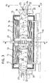
- the boiler shown in the drawing has an elongate, tubular furnace 10, at one end of which a burner 11 is mounted. The opposite end of the furnace communicates by way of a restricted passage 12 with an after-combustion chamber 13.
- a number of gas passage tubes 14 run parallell to the furnace tube and com municate in the embodiments according to Figure 1 and 3 with a collecting chamber 15, adjacent to the burner.
- a water shell 16 encloses in these embodiments the tubular furnace 10, the after-combustion chamber 13 and the smoke gas tubes 14.
- the water shell is in a conventional manner encased in insulations 17.
- the combustion gases are exhausted through a conduit 18. Water is supplied to the shell 16 by way of a conduit 19, and leaves the shell by a conduit 20.
- the boiler structure so far described is of a known design and ensures a high degree of efficiency, when it is provided with a conventional oil burner.
- the design has now been modified according to the invention in order to ensure a controlled combustion at a higher temperature.
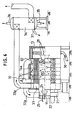
- This is obtained by pressurized gas being supplied to the furnace 10 by means of a fan 21 (see Fig. 4) through a slot-formed inlet 22, merging tangentially into the tubular furnace.
- the gas inlet 22 is subdivided into a primary part 22a and a secondary part 22b, by means of a displaceable disc 23. This is provided with a central opening 23a, in which the nozzle 11 of the burner is fitted.
- a funnel-shaped member 24, co-axial with the burner nozzle projects into the furnace tube, and keeps initially the primary and the secondary gas flows apart.
- the disc 23 is displaceable from outside the burner by means of an adjusting screw 25, passing through the end wall 26 of the furnace tube.
- an adjusting screw 25 passing through the end wall 26 of the furnace tube.
- the primary gas will flow in the same direction as the jet of fuel issued by the burner nozzle. Its content of oxygen will maintain combustion in a long, narrow flame, the highest temperature being obtained at the end of the flame.
- the secondary gas flow will follow the shell of the tubu lar furnace 10 and will rotate vertically towards the restricted passage 12. As the secondary gas is comparatively colder than the primary gas being heated by the flame, it will have a higher density and will thus, to a higher degree, be affected by the centrifugal force. The mixing of the secondary gas with the flame will be deferred, substantially until the gases reach the restricted passage 12. There the secondary gas will be mixed with the hot combustion products, and a final combustion occurs at high temperature in chamber 13.
- the gas supplied to the burner is air.
- the contaminated gas, possibly mixed with air is handled by the fan, and the amount of fuel supplied through the burner will be determined with respect to the amount of combustible matter carried by the gas.
- the rotating secondary gas flow will efficiently catch drops of oil or solid particles from the flame, so they will not be coked upon the hot furnace tube.
- the plant shown in Figure 3 contains two complete furnaces 10, directed axially towards each other, and having a common after-combustion chamber 13.
- the inlets for the combustion gas are arranged in such a manner that the gas flows, looking from one end of the plant, will rotate in opposite directions.
- the forceful rotation in this chamber may be used for separating out particles of soot or other solid combustion products.
- To that end the shell 27 of the after-combustion chamber 13 is provided with slots 28, which are directed tangentially outwards in the direction of rotation of the gases.
- the slots may be located at portion of the shell surface only, the portion being enclosed by a collecting wall 27a.
- the gases of combustion have a temperature of about 900 ° C, and thus a low density.
- the solid particles will be forced outwards against the collecting wall 27a, after having passed the slots 28, while the combustion gases will flow out through the smoke tubes 14.
- Figure 5 shows a pocket 29 for collecting the particles, which will be removed by means of a fan 30.
- the invention may advantageously be used for the combustion of byproducts from the cellulose pulp production.
- Figure 6 shows a further modification which ensures a high degree of preheating of the combustion gas, which may be exhausts from spray booths of the car industry.
- the tubular furnace 10 is not water- cooled, but the tubes 14a surrounding the furnace are externally swept by the incoming gases.
- the gas is supplied under pressure through a conduit 30.
- the space enclosing the furnace 10 and the tubes 14a is subdivided by a number of baffle plates 31, provided with suitably located openings, so the gas entering by way of conduit 30 will pass in a more or less helical path around the tubes to a turning chamber 32, from which the gases pass to the fan 21 by way of conduit 32a.
- the flow of the incoming gas outside the tubes 14a will ensure a high degree of pre-heating, which facilitates the following combustion.
- the combustion gases leaving the collecting chamber 33 are conveyed to a heat exchanger 34 of the condensing type by way of a conduit 33a.
- the heat reclaimed may be used for heating water which enters through pipe 35 and leaves the heat exchanger by way of pipe 36. Condensate is drained by way of pipe 37.
- the disc 23 is operated by a manual control means 25, but an automatic governing device can evidently be used. This may be guided by signals from some temperature sensor, for instance located in the after-combustion chamber 13.
- the tubular furnace 10 may in certain applications be mounted vertically.
- the rotating secondary air flow will form a film along the inner wall of the furnace tube ensuring an efficient cooling of the upper part thereof.
- the disk 23 makes possible an easy adjustment of the air flow relationship betwen primary and secondary air. A small amount of primary air and a corresponding fuel supply results in a low flame temperature, while the proportionally much bigger secondary air ensures satisfactory cooling. As steam is generated the proportions are changed and the flame temperature increases.
Landscapes
- Engineering & Computer Science (AREA)
- Mechanical Engineering (AREA)
- General Engineering & Computer Science (AREA)
- Environmental & Geological Engineering (AREA)
- Chemical & Material Sciences (AREA)
- Combustion & Propulsion (AREA)
Claims (6)
Priority Applications (2)
| Application Number | Priority Date | Filing Date | Title |
|---|---|---|---|
| DE8787850246T DE3766618D1 (de) | 1987-08-17 | 1987-08-17 | Verbrennungsanlage mit mindestens einer rohrfoermigen verbrennungskammer. |
| EP19870850246 EP0304532B1 (de) | 1987-08-17 | 1987-08-17 | Verbrennungsanlage mit mindestens einer rohrförmigen Verbrennungskammer |
Applications Claiming Priority (1)
| Application Number | Priority Date | Filing Date | Title |
|---|---|---|---|
| EP19870850246 EP0304532B1 (de) | 1987-08-17 | 1987-08-17 | Verbrennungsanlage mit mindestens einer rohrförmigen Verbrennungskammer |
Publications (2)
| Publication Number | Publication Date |
|---|---|
| EP0304532A1 EP0304532A1 (de) | 1989-03-01 |
| EP0304532B1 true EP0304532B1 (de) | 1990-12-05 |
Family
ID=8198486
Family Applications (1)
| Application Number | Title | Priority Date | Filing Date |
|---|---|---|---|
| EP19870850246 Expired EP0304532B1 (de) | 1987-08-17 | 1987-08-17 | Verbrennungsanlage mit mindestens einer rohrförmigen Verbrennungskammer |
Country Status (2)
| Country | Link |
|---|---|
| EP (1) | EP0304532B1 (de) |
| DE (1) | DE3766618D1 (de) |
Families Citing this family (3)
| Publication number | Priority date | Publication date | Assignee | Title |
|---|---|---|---|---|
| IT1248599B (it) * | 1991-05-10 | 1995-01-19 | Bono En S P A | Procedimento ed apparecchiatura per la distruzione termica di reflui industriali inquinanti |
| FR2688577A1 (fr) * | 1992-03-10 | 1993-09-17 | Dumoutier Massetat Sa | Dispositif d'epuration des effluents gazeux. |
| DE102015205516A1 (de) * | 2014-12-22 | 2016-06-23 | Dürr Systems GmbH | Vorrichtung und Verfahren zur thermischen Abgasreinigung |
Family Cites Families (5)
| Publication number | Priority date | Publication date | Assignee | Title |
|---|---|---|---|---|
| DE2348909A1 (de) * | 1973-09-28 | 1975-04-10 | Gimborn Probat Werke | Nachverbrennungsanlage |
| DE2352204B2 (de) * | 1973-10-18 | 1976-01-22 | Katec Katalytische Lufttechnik Betz & Co, 6461 Neuenhaßlau | Verbrennungseinrichtung zur verbrennung von stoerstoffen in abgasen |
| SE384078B (sv) * | 1973-11-19 | 1976-04-12 | Ostbo Nils Ab | Ugn for destruktion av luktemnen i gaser |
| US4154567A (en) * | 1977-01-07 | 1979-05-15 | Continental Carbon Company | Method and apparatus for the combustion of waste gases |
| DE3345611A1 (de) * | 1983-12-16 | 1985-06-27 | Deutsche Babcock Werke AG, 4200 Oberhausen | Brenner zur erzeugung von inertgas |
-
1987
- 1987-08-17 EP EP19870850246 patent/EP0304532B1/de not_active Expired
- 1987-08-17 DE DE8787850246T patent/DE3766618D1/de not_active Expired - Lifetime
Also Published As
| Publication number | Publication date |
|---|---|
| EP0304532A1 (de) | 1989-03-01 |
| DE3766618D1 (de) | 1991-01-17 |
Similar Documents
| Publication | Publication Date | Title |
|---|---|---|
| CA1144470A (en) | Process and apparatus utilizing common structure for combustion, gas fixation, or waste heat recovery | |
| US4254715A (en) | Solid fuel combustor and method of burning | |
| US4270467A (en) | Low mass flow waste fuel incinerator | |
| CA2201259C (en) | High efficiency direct-contact high temperature water heater | |
| EP0440281B1 (de) | Brenner für festen und flüssigen oder gasförmigen Brennstoff | |
| DK162112B (da) | Trykladet, kulfyret dampgenerator | |
| US3642061A (en) | Heat exchanger | |
| EP0304532A1 (de) | Verbrennungsanlage mit mindestens einer rohrförmigen Verbrennungskammer | |
| RU2036376C1 (ru) | Система подготовки водоугольного топлива к сжиганию в энергетической котельной установке | |
| US3773462A (en) | Heat exchanger | |
| GB2218787A (en) | Steam boilers | |
| NL8403236A (nl) | Verwarmingsketel voor een centrale verwarmingsinstallatie. | |
| US5317979A (en) | Method and apparatus for the complete, dry desulphurization of combustion waste gases comprising SO2 and dust | |
| RU2172890C2 (ru) | Способ и установка для генерирования горячего газа | |
| SU1509575A1 (ru) | Способ рециркул ции дымовых газов и система дл его осуществлени | |
| US20230349545A1 (en) | Steam Generator | |
| RU2072479C1 (ru) | Пылесистема | |
| GB2231949A (en) | Gas burner | |
| US6003475A (en) | Plant for the combustion of fossil fuel and biomaterial or waste | |
| WO2008104859A2 (en) | Boiler and method for operating said boiler | |
| KR830002969Y1 (ko) | 온수보일러용 왕겨연소기 | |
| US6021724A (en) | Cyclone furnace for retrofit applications | |
| GB1432183A (en) | Incinerator | |
| SU1006872A2 (ru) | Устройство дл сжигани сбросных газов | |
| KR790002209Y1 (ko) | 온수 가열기 겸용난로 |
Legal Events
| Date | Code | Title | Description |
|---|---|---|---|
| PUAI | Public reference made under article 153(3) epc to a published international application that has entered the european phase |
Free format text: ORIGINAL CODE: 0009012 |
|
| 17P | Request for examination filed |
Effective date: 19881021 |
|
| AK | Designated contracting states |
Kind code of ref document: A1 Designated state(s): DE FR GB IT NL SE |
|
| 17Q | First examination report despatched |
Effective date: 19890613 |
|
| 18D | Application deemed to be withdrawn |
Effective date: 19900131 |
|
| 18RA | Request filed for re-establishment of rights before grant |
Effective date: 19900809 |
|
| GRAA | (expected) grant |
Free format text: ORIGINAL CODE: 0009210 |
|
| 18RR | Decision to grant the request for re-establishment of rights before grant |
Free format text: 901017 ANGENOMMEN |
|
| AK | Designated contracting states |
Kind code of ref document: B1 Designated state(s): DE FR GB IT NL SE |
|
| PG25 | Lapsed in a contracting state [announced via postgrant information from national office to epo] |
Ref country code: IT Free format text: LAPSE BECAUSE OF FAILURE TO SUBMIT A TRANSLATION OF THE DESCRIPTION OR TO PAY THE FEE WITHIN THE PRE;WARNING: LAPSES OF ITALIAN PATENTS WITH EFFECTIVE DATE BEFORE 2007 MAY HAVE OCCURRED AT ANY TIME BEFORE 2007. THE CORRECT EFFECTIVE DATE MAY BE DIFFERENT FROM THE ONE RECORDED.SCRIBED TIME-LIMIT Effective date: 19901205 Ref country code: FR Effective date: 19901205 Ref country code: NL Effective date: 19901205 |
|
| REF | Corresponds to: |
Ref document number: 3766618 Country of ref document: DE Date of ref document: 19910117 |
|
| EN | Fr: translation not filed | ||
| NLV1 | Nl: lapsed or annulled due to failure to fulfill the requirements of art. 29p and 29m of the patents act | ||
| PLBE | No opposition filed within time limit |
Free format text: ORIGINAL CODE: 0009261 |
|
| STAA | Information on the status of an ep patent application or granted ep patent |
Free format text: STATUS: NO OPPOSITION FILED WITHIN TIME LIMIT |
|
| 26N | No opposition filed | ||
| EAL | Se: european patent in force in sweden |
Ref document number: 87850246.7 |
|
| PG25 | Lapsed in a contracting state [announced via postgrant information from national office to epo] |
Ref country code: SE Effective date: 19950818 |
|
| EUG | Se: european patent has lapsed |
Ref document number: 87850246.7 |
|
| PGFP | Annual fee paid to national office [announced via postgrant information from national office to epo] |
Ref country code: GB Payment date: 19980217 Year of fee payment: 11 |
|
| PGFP | Annual fee paid to national office [announced via postgrant information from national office to epo] |
Ref country code: SE Payment date: 19980219 Year of fee payment: 11 |
|
| PGFP | Annual fee paid to national office [announced via postgrant information from national office to epo] |
Ref country code: DE Payment date: 19980323 Year of fee payment: 11 |
|
| PG25 | Lapsed in a contracting state [announced via postgrant information from national office to epo] |
Ref country code: GB Free format text: LAPSE BECAUSE OF NON-PAYMENT OF DUE FEES Effective date: 19980817 |
|
| GBPC | Gb: european patent ceased through non-payment of renewal fee |
Effective date: 19980817 |
|
| PG25 | Lapsed in a contracting state [announced via postgrant information from national office to epo] |
Ref country code: DE Free format text: LAPSE BECAUSE OF NON-PAYMENT OF DUE FEES Effective date: 19990601 |