EP0304600B1 - Gegenstandidentifizierungsverfahren - Google Patents
Gegenstandidentifizierungsverfahren Download PDFInfo
- Publication number
- EP0304600B1 EP0304600B1 EP88111210A EP88111210A EP0304600B1 EP 0304600 B1 EP0304600 B1 EP 0304600B1 EP 88111210 A EP88111210 A EP 88111210A EP 88111210 A EP88111210 A EP 88111210A EP 0304600 B1 EP0304600 B1 EP 0304600B1
- Authority
- EP
- European Patent Office
- Prior art keywords
- objects
- pattern
- brightness
- scanning
- patterns
- Prior art date
- Legal status (The legal status is an assumption and is not a legal conclusion. Google has not performed a legal analysis and makes no representation as to the accuracy of the status listed.)
- Expired
Links
Images


Classifications
-
- G—PHYSICS
- G06—COMPUTING OR CALCULATING; COUNTING
- G06V—IMAGE OR VIDEO RECOGNITION OR UNDERSTANDING
- G06V10/00—Arrangements for image or video recognition or understanding
- G06V10/20—Image preprocessing
Definitions
- This invention relates to a method of identifying an object capable of identifying rod-like objects to be detected from an image data comprising one picture of a plurality of said objects in various orientations.
- an object is photographed with an image pick-up device of an industrial television (ITV) camera for example, the photographed picture is scanned, and a bright and dark pattern (brightness pattern) comprising image data of a predetermined number of picture elements which are contiguous in the direction of scanning is compared with a reference pattern which has been prepared previously and representing the brightness of the object.
- ITV industrial television
- a method of identifying rod-like objects characterized by the steps of sequentially extracting a set of object brightness patterns including a predetermined number picture elements which are contiguous in a predetermined scanning direction, from picture element data in a predetermined field of view in which a plurality of the rod-like objects to be identified are scattered while shifting the brightness patterns by one picture element in the scanning direction; comparing the object brightness patterns with a prepared reference pattern representing brightnesses of a predetermined number of picture elements in a transverse direction of the objects; where the brightness pattern in the transverse direction of the objects varies in accordance with the orientations of the objects, preparing reference brightness patterns in the transverse direction of the objects lying substantially perpendicularly to the horizontal, vertical, right 45° upper and right 45° lower directions in the predetermined field of view, in each of the four directions; extracting object brightness patterns in each of four scanning directions of the horizontal, vertical, right 45° upper and right 45° lower directions in the field of view, from the picture image data in the predetermined field of view; and utilizing
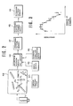
- a monitor 42 displays a picture of the plurality of rods in response to the image data sent from the ITV camera 11. Further, the monitor 42 displays a cursor 2a freee to move in the vertical and horizontal directions of the monitor picture by the manipulation of a cursor shifting lever 43.
- a brightness pattern derive out circuit 44 is provided for deriving out a brightness pattern comprising the picture image data comprising ten contiguous picture elements from the image data inputted to the monitor 42. More particularly, the derive out circuit 44 derives out a brightness pattern in a scanning direction designated by a scanning direction designation switch taking the shifted position of the cursor 2a as a reference when a write switch 45 is closed.
- the scanning direction designation switch 46 is constructed to designate either one of the horizontal direction (shown by arrow A), the vertical direction (shown by arrow B), right 45° upper direction (shown by arrow C) and right 45° lower direction (shown by arrow D).
- a brightness pattern memory device 47 temporarily stores a plurality of brightness patterns derived out by the brightness pattern derive out circuit 44, while a reference pattern forming circuit 48 forms an optimum reference pattern from the plurality of brightness patterns.
- a method of forming the reference pattern from the plurality of brightness patterns may be used a method using. Lagrage's method of indefinite multipliers or a method for obtaining an average value or a center value.
- the reference pattern prepared in this manner is stored in a memory area of the reference pattern memory device 49 corresponding to the direction of scanning designated by the scanning direction designation switch 46.
- either one of the four scanning directions, for example, the horizontal direction shown by arrow A is selected by operating the scanning direction designation switch 46. While viewing the picture on the monitor 42, the operator searches a picture image of the rod in a direction substantially perpendicular to the direction A and then manipulates the cursor shifting lever 43 to shift the cursor to the central position P1 of the picture. Thereafter, the operator turns ON the write switch 45.
- a plurality of sets of the brightness patterns in the transverse direction of the rod substantially perpendicular to the direction A would be stored in the brightness pattern memory device 47, and the reference pattern is formed by the reference pattern forming circuit 48 based on the plurality of sets of the brightness patterns.
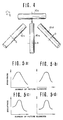
- Fig.3 shows the relationship among 4 sets of brightness patterns shown by symbols ( ⁇ , ⁇ , ⁇ and x and the reference pattern ( ⁇ ) prepared from these brightness patterns.
- direction D is designated as the scanning direction
- a reference pattern in this scanning direction can be prepared by shifting the cursor 2a to the center position P2 of the rod perpendicular to the designated direction.
- the reference pattern memory device 49 stores four reference patterns corresponding to the four scanning directions.
- rods 10a, 10b, 10c and 10d present respectively in the orthogonal directions A, B, C and D as shown in Fig.4, and when the rods are illuminated in the direction of arrow E, the reference patterns formed for rods 10a, 10b, 10c and 10d would have different patterns as shown in Figs. 5a - 5d.
- n 1 to designate the scanning direction of the picture image data of one picture.
- a reference pattern corresponding to n is read out from the reference pattern memory device 49.
- the reference pattern memory device 49 is constructed to store reference patterns in the four scanning directions so that the reference patterns can be read out according to the value of n.
- the brightness pattern of data of a predetermined number of elements which are contigous in the scanning direction which corresponds to n are read out from the picture image data of one picture corresponding to the position of i.
- the brightness pattern is compared with the read out reference pattern to judge whether the read out brightness pattern is the brightness pattern of the cross-section of the rod or not.
- the position of the rod is detected based on the position of i when the brightness pattern is that of the cross-section and to store this position.
- the programm is transferred to step 56 to store position detection.
- step 55 1 is added to i, and at step 57 a judgment is made as to whether the position of i is the scanning completion position or not. If the result of this judgment is NO, the program is returned to step 53 at which a new brightness pattern displaced by one picture element in the scanning direction corresponding to n is read out.
- step 53 By executing the processings and judgments until completion of a scanning, it is possible to detect and store the cross-sectional position of a rod presenting within ⁇ 22.5° about a direction orthogonal to the direction of scanning corresponding to n.
- 1 is added to n to designates another scanning position at step 58.
- the program is returned to step 51.
- a new reference pattern is read out from the reference memory device corresponding to the renewed value of n.
- the scanning is made in a scanning direction corresponding to n by using the read out reference pattern for detecting the cross-sectional position of the rod in the same manner as above described.
- n becomes 5 thus ending the direction of rods of one picture.
- rods were used as the objects to be detected, however, this invention can be applied to other rod-like objects with cross-sectional configuration, for example, a hexagonal cross-section.
- the rod-like object is scanned in four discrete directions so as to use an optimum reference pattern for each scanning direction, it is possible to accurately detect objects scattered in all orientations irrespective of the position of the source of illumination.
Landscapes
- Engineering & Computer Science (AREA)
- Physics & Mathematics (AREA)
- General Physics & Mathematics (AREA)
- Multimedia (AREA)
- Theoretical Computer Science (AREA)
- Image Analysis (AREA)
- Image Processing (AREA)
Claims (1)
- Gegenstandidentifizierungsverfahren zum Identifizieren von stabförmigen Gegenständen, dadurch gekennzeichnet,
daß ein Satz von Gegenstands-Helligkeitsmustern, wobei jedes Muster eine vorherbestimmte Anzahl von Bildelementen enthält, welche in einer vorherbestimmten Abtastrichtung aneinanderstoßen, aus Bildelementdaten in einem vorherbestimmten Blickfeld sequentiell extrahiert wird, in welchem eine Anzahl der stabförmigen, zu identifizierenden Gegenstände verstreut sind, wobei die Helligkeitsmuster um ein Bildelement in der Abtastrichtung sukzessiv verschoben werden;
daß die Gegenstands-Helligkeitsmuster mit einem vorbereiteten Referenzmuster verglichen werden, welches Helligkeiten einer vorherbestimmten Anzahl von Bildelementen in einer Querrichtung der Gegenstände darstellt;
daß, wenn sich das Helligkeitsmuster in der Querrichtung der Gegenstände entsprechend Ausrichtungen der Gegenstände ändert, Referenz-Helligkeitsmuster in der Querrichtung der Gegenstände, welche im wesentlichen senkrecht zu der horizontalen, vertikalen, unter 45° nach rechts oben und unter 45° nach rechts unten weisenden Richtung in dem vorherbestimmten Blickfeld liegen, in jeder der vier Richtungen vorbereitet werden;
daß Gegenstands-Helligkeitsmuster in jeder der vier Abtastrichtungen der horizontalen, vertikalen, unter 45° nach rechts oben und unter 45° nach rechts unten weisenden Richtungen in dem Blickfeld, aus den Bildelementdaten in dem vorherbestimmten Blickfeld extrahiert werden, und
daß eines der vorbereiteten vier Referenz-Helligkeitsmuster, welche entsprechend der Abtastrichtung des Gegenstands-Helligkeitsmusters ausgewählt worden sind, für einen Vergleich mit dem Gegenstands-Helligkeitsmuster verwendet wird, um dadurch beliebig ausgerichtete, verstreute, stabförmige Gegenstände zu identifizieren.
Applications Claiming Priority (2)
| Application Number | Priority Date | Filing Date | Title |
|---|---|---|---|
| JP58078792A JPS59202573A (ja) | 1983-05-04 | 1983-05-04 | 棒状物体の検出方法 |
| JP78792/83 | 1983-05-04 |
Related Parent Applications (1)
| Application Number | Title | Priority Date | Filing Date |
|---|---|---|---|
| EP84103973.8 Division | 1984-04-09 |
Publications (3)
| Publication Number | Publication Date |
|---|---|
| EP0304600A2 EP0304600A2 (de) | 1989-03-01 |
| EP0304600A3 EP0304600A3 (en) | 1989-07-05 |
| EP0304600B1 true EP0304600B1 (de) | 1991-11-27 |
Family
ID=13671721
Family Applications (1)
| Application Number | Title | Priority Date | Filing Date |
|---|---|---|---|
| EP88111210A Expired EP0304600B1 (de) | 1983-05-04 | 1984-04-09 | Gegenstandidentifizierungsverfahren |
Country Status (3)
| Country | Link |
|---|---|
| EP (1) | EP0304600B1 (de) |
| JP (1) | JPS59202573A (de) |
| DE (1) | DE3485311D1 (de) |
Families Citing this family (1)
| Publication number | Priority date | Publication date | Assignee | Title |
|---|---|---|---|---|
| US7796804B2 (en) * | 2007-07-20 | 2010-09-14 | Kla-Tencor Corp. | Methods for generating a standard reference die for use in a die to standard reference die inspection and methods for inspecting a wafer |
Family Cites Families (3)
| Publication number | Priority date | Publication date | Assignee | Title |
|---|---|---|---|---|
| JPS5241015B2 (de) * | 1972-10-13 | 1977-10-15 | ||
| JPS6038755B2 (ja) * | 1980-04-24 | 1985-09-03 | 沖電気工業株式会社 | 特徴抽出方式 |
| JPS582984A (ja) * | 1981-06-29 | 1983-01-08 | Nec Corp | 光学式文字認識装置 |
-
1983
- 1983-05-04 JP JP58078792A patent/JPS59202573A/ja active Granted
-
1984
- 1984-04-09 DE DE8888111210T patent/DE3485311D1/de not_active Expired - Lifetime
- 1984-04-09 EP EP88111210A patent/EP0304600B1/de not_active Expired
Also Published As
| Publication number | Publication date |
|---|---|
| JPS59202573A (ja) | 1984-11-16 |
| DE3485311D1 (de) | 1992-01-09 |
| EP0304600A3 (en) | 1989-07-05 |
| EP0304600A2 (de) | 1989-03-01 |
| JPH0139148B2 (de) | 1989-08-18 |
Similar Documents
| Publication | Publication Date | Title |
|---|---|---|
| US4747148A (en) | Method of identifying objects | |
| KR890002287B1 (ko) | 패턴 매칭방법 및 장치 | |
| US4941192A (en) | Method and apparatus for recognizing pattern of gray level image | |
| US20060018534A1 (en) | Technique for detecting a defect of an object by area segmentation of a color image of the object | |
| EP0649030A1 (de) | Kontaktelementüberprüfungsmethode und Kontaktelementüberprüfungsvorrichtung | |
| US4642813A (en) | Electro-optical quality control inspection of elements on a product | |
| GB2212353A (en) | Machine vision | |
| US5111411A (en) | Object sorting system | |
| US6320977B1 (en) | Method and apparatus for positional detection using pattern matching process | |
| EP0094824B1 (de) | Bildverarbeitungseinrichtung zur kontinuierlichen Extraktion von Merkmalen von kleinen Gebieten in einem Bild | |
| EP0304600B1 (de) | Gegenstandidentifizierungsverfahren | |
| US6330521B1 (en) | Optical scanner alignment indicator method and apparatus | |
| US6675120B2 (en) | Color optical inspection system | |
| KR19990077774A (ko) | 지문 이미지 처리장치 및 지문 이미지 처리방법 | |
| JP3067846B2 (ja) | パターン検査方法及び装置 | |
| EP0228963A2 (de) | Untersuchungssystem durch Linienabtastung für Schaltungsplatten | |
| KR920005243B1 (ko) | 영상에서 목적 패턴의 위치를 검지하는 방법 | |
| JP2005520350A (ja) | ウエハマッピング装置及び方法 | |
| JPH05129397A (ja) | 異物検出方法及び装置 | |
| EP0297627A2 (de) | Verfahren zum Identifizieren von Objekten | |
| JPH0687264B2 (ja) | 画像の2値化方式 | |
| JP2628863B2 (ja) | 視覚認識装置 | |
| JPH05210737A (ja) | パターン認識方法 | |
| JP2971793B2 (ja) | 位置検出装置 | |
| Koezuka et al. | High-Seed 3-D Vision System Using Range And Intensity Images Covering A Wide Area |
Legal Events
| Date | Code | Title | Description |
|---|---|---|---|
| PUAI | Public reference made under article 153(3) epc to a published international application that has entered the european phase |
Free format text: ORIGINAL CODE: 0009012 |
|
| 17P | Request for examination filed |
Effective date: 19880713 |
|
| AC | Divisional application: reference to earlier application |
Ref document number: 124789 Country of ref document: EP |
|
| AK | Designated contracting states |
Kind code of ref document: A2 Designated state(s): CH DE FR GB IT LI SE |
|
| PUAL | Search report despatched |
Free format text: ORIGINAL CODE: 0009013 |
|
| AK | Designated contracting states |
Kind code of ref document: A3 Designated state(s): CH DE FR GB IT LI SE |
|
| 17Q | First examination report despatched |
Effective date: 19910128 |
|
| GRAA | (expected) grant |
Free format text: ORIGINAL CODE: 0009210 |
|
| AC | Divisional application: reference to earlier application |
Ref document number: 124789 Country of ref document: EP |
|
| AK | Designated contracting states |
Kind code of ref document: B1 Designated state(s): CH DE FR GB IT LI SE |
|
| ITF | It: translation for a ep patent filed | ||
| REF | Corresponds to: |
Ref document number: 3485311 Country of ref document: DE Date of ref document: 19920109 |
|
| ET | Fr: translation filed | ||
| PGFP | Annual fee paid to national office [announced via postgrant information from national office to epo] |
Ref country code: FR Payment date: 19920613 Year of fee payment: 9 |
|
| PLBE | No opposition filed within time limit |
Free format text: ORIGINAL CODE: 0009261 |
|
| STAA | Information on the status of an ep patent application or granted ep patent |
Free format text: STATUS: NO OPPOSITION FILED WITHIN TIME LIMIT |
|
| 26N | No opposition filed | ||
| PG25 | Lapsed in a contracting state [announced via postgrant information from national office to epo] |
Ref country code: FR Effective date: 19931229 |
|
| REG | Reference to a national code |
Ref country code: FR Ref legal event code: ST |
|
| PGFP | Annual fee paid to national office [announced via postgrant information from national office to epo] |
Ref country code: GB Payment date: 19940330 Year of fee payment: 11 |
|
| PGFP | Annual fee paid to national office [announced via postgrant information from national office to epo] |
Ref country code: DE Payment date: 19940408 Year of fee payment: 11 |
|
| PGFP | Annual fee paid to national office [announced via postgrant information from national office to epo] |
Ref country code: CH Payment date: 19940413 Year of fee payment: 11 |
|
| PGFP | Annual fee paid to national office [announced via postgrant information from national office to epo] |
Ref country code: SE Payment date: 19940415 Year of fee payment: 11 |
|
| EAL | Se: european patent in force in sweden |
Ref document number: 88111210.6 |
|
| PG25 | Lapsed in a contracting state [announced via postgrant information from national office to epo] |
Ref country code: GB Effective date: 19950409 |
|
| PG25 | Lapsed in a contracting state [announced via postgrant information from national office to epo] |
Ref country code: SE Effective date: 19950410 |
|
| PG25 | Lapsed in a contracting state [announced via postgrant information from national office to epo] |
Ref country code: LI Effective date: 19950430 Ref country code: CH Effective date: 19950430 |
|
| GBPC | Gb: european patent ceased through non-payment of renewal fee |
Effective date: 19950409 |
|
| REG | Reference to a national code |
Ref country code: CH Ref legal event code: PL |
|
| PG25 | Lapsed in a contracting state [announced via postgrant information from national office to epo] |
Ref country code: DE Effective date: 19960103 |
|
| EUG | Se: european patent has lapsed |
Ref document number: 88111210.6 |