EP0304660A2 - Aile téléscopique - Google Patents
Aile téléscopique Download PDFInfo
- Publication number
- EP0304660A2 EP0304660A2 EP88112193A EP88112193A EP0304660A2 EP 0304660 A2 EP0304660 A2 EP 0304660A2 EP 88112193 A EP88112193 A EP 88112193A EP 88112193 A EP88112193 A EP 88112193A EP 0304660 A2 EP0304660 A2 EP 0304660A2
- Authority
- EP
- European Patent Office
- Prior art keywords
- wing
- sections
- spar
- section
- skin
- Prior art date
- Legal status (The legal status is an assumption and is not a legal conclusion. Google has not performed a legal analysis and makes no representation as to the accuracy of the status listed.)
- Granted
Links
Images





Classifications
-
- B—PERFORMING OPERATIONS; TRANSPORTING
- B23—MACHINE TOOLS; METAL-WORKING NOT OTHERWISE PROVIDED FOR
- B23Q—DETAILS, COMPONENTS, OR ACCESSORIES FOR MACHINE TOOLS, e.g. ARRANGEMENTS FOR COPYING OR CONTROLLING; MACHINE TOOLS IN GENERAL CHARACTERISED BY THE CONSTRUCTION OF PARTICULAR DETAILS OR COMPONENTS; COMBINATIONS OR ASSOCIATIONS OF METAL-WORKING MACHINES, NOT DIRECTED TO A PARTICULAR RESULT
- B23Q1/00—Members which are comprised in the general build-up of a form of machine, particularly relatively large fixed members
- B23Q1/25—Movable or adjustable work or tool supports
- B23Q1/44—Movable or adjustable work or tool supports using particular mechanisms
- B23Q1/56—Movable or adjustable work or tool supports using particular mechanisms with sliding pairs only, the sliding pairs being the first two elements of the mechanism
- B23Q1/60—Movable or adjustable work or tool supports using particular mechanisms with sliding pairs only, the sliding pairs being the first two elements of the mechanism two sliding pairs only, the sliding pairs being the first two elements of the mechanism
- B23Q1/601—Movable or adjustable work or tool supports using particular mechanisms with sliding pairs only, the sliding pairs being the first two elements of the mechanism two sliding pairs only, the sliding pairs being the first two elements of the mechanism a single sliding pair followed parallelly by a single sliding pair
-
- B—PERFORMING OPERATIONS; TRANSPORTING
- B64—AIRCRAFT; AVIATION; COSMONAUTICS
- B64C—AEROPLANES; HELICOPTERS
- B64C3/00—Wings
- B64C3/38—Adjustment of complete wings or parts thereof
- B64C3/54—Varying in area
Definitions
- the long wingspan is a disadvantage, limiting the flexibility of use and a more universal utilization of the airplane on the ground.
- the need for a design which will allow a substantial reduction of the wing span on the ground is obvious.
- Various design alternatives for reduction of the wing span, such as folding wings, which are used on military aircraft on carriers have been developed, and while the geometry and mechanism for folding wings is relatively simple, the concept is not suitable for applications where the aircraft is moved about on the ground at highway speeds. For one thing, wings folded up against the side of the fuselage present a large surface area which can be affected by side winds; and the center of gravity is raised or moved rearwardly, which is detrimental.
- Another concept for reducing the wing span is to telescope the wing, which has the possibility of substantially contracting the span without many of the structural and other disadvantages of the folding wing.
- the center of gravity of the telescopic wing is not changed, and the side area affected by winds does not exist.
- a telescopic wing used a plurality of wing sections, each consisting of the skin, a rib, and a tubular portion with an internally threaded collar at its end that meshes with threads on a short tubular spar section.
- the tubular spar sections are connected to one another, and are rotatable with respect to one another. Extension and retraction of the spar sections is supposed to be accomplished by rotating the innermost spar section, which is then supposed to screw into the next adjoining spar section. However, without some means to hold one spar section against turning while the next adjoining spar section is rotated, there can be no screwing together or apart.
- the spar is made up of several short tubular sections, each of which is rotatably connected to the next adjoining spars at both ends, the spar assembly has no torsional rigidity, and apparently torsional loads are supposed to be carried by the skin, which is completely impractical, since the skin sections are connected by rollers.
- the primary object of the present invention is to provide a telescoping wing that can be retracted to less than 30% of the extended wing span, which makes it feasible for use in a roadable vehicle that travels on the highways.
- Another object of the invention is to provide a telescoping wing in which the spar retains its full load-carrying capability in the retracted as well as the extended condition, and in all intermediate positions.
- Still a further object of the invention is to provide a telescoping wing wherein during extension and retraction of the wing, all load-carrying elements of the spar remain connected to each other by three linear and two rotational axes; and only one rotational degree of freedom is required for accomplishing extension and retraction of the wing.
- Fig. 1 the telescopic wing of the invention is shown in the extended condition, comprising a central housing 1, left wing half 2, and right wing half 3.
- Each of the two wing halves consists of a plurality of short wing sections 4, comprising skin sections 5 attached to ribs 6, and carried by a tubular rear spar 7 and tubular front spar 8.
- Each of the spars 7 and 8 is sub-divided into non-rotatable spar sections 9 and rotatable spar sections 10; the rotatable and non-rotatable spar sections being disposed in alternating disposition so that each rotatable spar section is joined at opposite ends to two non-rotatable spar sections.
- the rotatable and non-rotatable spar sections overlap one another at 11, and are adapted to telescope with respect to one another when the wing is retracted, as will be described presently.
- the skin sections 5 also overlap at 12 and are slidable over one another.
- At the tip end of the outer wing section is an end plate 13, which closes the outer wing section.
- the trailing edge of each wing half is formed by telescoping aileron sections 14 and flap sections 15.
- the skin 5 is made of a thin sheet of rigid material, preferably a composite such as carbon fiber or the like, shaped to the airfoil section as defined by the rib 6.
- the wing sections 4 may be constructed as shown in Fig. 2, wherein the spar sections 9, 10 and skin section 5 both extend laterally from the same side of the rib 6, with the spar contained within the envelope of the skin.
- the wing sections 4 may be constructed as shown in Fig. 3, wherein the spar sections 9, 10 and skin section 5 extend laterally from opposite sides of the rib 6.
- Figs. 2 and 3 Each of the two embodiments of Figs. 2 and 3 has certain advantages as well as disadvantages over the other, which would be taken into consideration during the design of the aircraft.
- various alternative configurations are possible, wherein the outer spar sections telescope into or over the adjoining inner spar section, and the outer skin section may slide over or under the adjoining inner skin section.
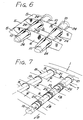
- Three of these possible alternative arrangements are shown in Figs. 4, 5 and 6, which will now be described.
- Fig. 4 is a horizontal section of a wing, taken through the axes of the spars 7, 8, in which the left-hand wing half 2 is retracted, and the right-hand wing half 3 is extended, and in which the skin 5 and spar sections 9 or 10 are as shown in Fig. 2.
- the outer spar sections telescope into the adjoining inner spar sections, which has the advantageous feature of providing the largest spar diameter at the root end of the wing, and the smallest spar diameter at the tip end.
- the outer skin sections telescope over the adjoining inner skin sections, which results in the outer wing section being slightly larger than the root wing section.
- the central housing 1 has two laterally spaced, parallel walls 20, and projecting laterally from the walls 20 on the axes of the spars 7, 8 are collars 21, into which the root spar sections 9 are inserted and fixedly held. As mentioned earlier, the spar sections 9 are non-rotatable.
- each of the ribs 6 has holes 22 provided therein, through which the spars of the outer wing half pass freely.
- the advantage of this construction is that the largest spar diameter is at the wing root, and the smallest spar diameter is at the wing tip.
- Another advantage is that the skin sections are gathered inside the central housing 1, instead of on the outside, as in Fig. 4, and the smallest wing section is at the tip end of the wing, and the largest wing section is at the root end.
- multiple spars can be used, of which one spar axis 23′ is designated in Fig.5.
- the axes of the other two spars are indicated at 8′ and 7′.
- Fig.6 shows another embodiment of the invention, in which the skin and spar portions of each wing section telescope into the respective skin and spar portions of the next adjoining wing section toward the wing root.
- another member 24 is provided which extends from the rib 6 on the same side as the skin section 5 and is connected at its other end to the respective spar portion 9 or 10, which is contained inside member 24.
- Member 24 may be slightly conical as shown in Fig. 6, but this is not essential.
- the wing design is optimized without offsetting the spars, and allows use of the invention in wings of large dihedral angle.
- Figs. 7 and 8 illustrate the dynamic principle of the invention whereby the spar is extended or retracted by rotating certain spar portions while preventing rotation of the other spar portions.
- the outer spar section telescopes into the adjoining inner spar section
- the innermost spar section 9 extends into and is fixedly connected to collar 21 on central housing 1.
- the adjoining rotatable spar section 10 extends into the outer end of the innermost spar section 9 and is rotatably interconnected by a rolling element bushing 25.
- rotatable spar section 10 telescopes over the rear end of the next adjoining non-rotatable spar section 9, and is interconnected to the latter by another rolling element bushing 25.
- the rolling element bushings 25 each comprise a plurality of rolling elements such as ball bearings 26 or, alternatively, tapered bearings, roller bearings, or needle bearings, which are confined within a cylindrical, sleeve-like cage 27 that is disposed within the space between the overlapping spar portions 9 and 10.
- the balls 26 run in spiral, or helical, channels 28 and 29 formed in the opposed cylindrical surfaces of the overlapping spar portions, and these channels serve as races for the balls, and are the equivalent of screw threads.
- the ball bearings 26 or other rolling elements are preloaded in their races to eliminate backlash.
- the bushings 25 of Fig. 8 show only 5 or 6 rows of balls for the purpose of clarity of illustration, but a more typical bushing would include 10 to 20 rows of balls, as shown in Fig. 17.
- the right-hand end of rotatable spar portion 10 has a right-hand channel, or thread, formed in its outer surface, while non-rotatable spar portion 9 has a right-hand channel, or thread, formed in its inner surface.
- the fragmentary portion of bushing 25 shown in Fig. 9 depicts the right-hand end of spar portion 10 and its overlapping spar portion 9 of Fig. 8.
- spar portion 10 has a left-hand channel, or thread, formed in its inner surface, and its associated non-rotatable spar portion 9, which extends into the spar portion 10, has a left-hand channel, or thread, formed in its outer surface.
- Fig. 10 shows an alternative ball-bearing arrangement that might be used in the rolling element bushing 25.
- the ball bearings 26 are disposed in shallow, U-shaped channels 28′ in spar section 10′, and 29′ in spar section 9′.
- the cage 27′ has portions that are offset with respect to one another, as shown in Fig. 10, to confine the balls.
- the rotatable spar sections 10 are driven by a telescopic drive mechanism 32 shown more or less schematically in Fig. 11, and also shown in more detail in Fig. 16.
- the telescopic drive mechanism 32 is connected to rotatable spar sections 10 by disks 33 (Fig. 16); and to non-rotatable spar sections 9 by disks 34.
- Disks 33 are fixedly connected to portions of the drive mechanism 32, as will be described presently, while disks 34 are rotatably connected by bearings 35 to other portions of the drive mechanism. As shown in Fig.
- the drive mechanism 32 consists of a plurality of tubular frames 36 and 37, each of which comprises a pair of axially spaced rings 38 and 39 that are joined together by a plurality of circumferentially spaced parallel bars 40. Rings 38 are slightly smaller in diameter than rings 39 and are attached to the inside surfaces of bars 40, while rings 39 are attached to the outside surfaces of bars 40. This arrangement allows the ring 38 of frame section 37 to move axially within bars 40 of frame section 36, while bars 40 of tubular frame 36 are in sliding contact with bars 40 of tubular frame 37.
- disks 33 of rotatable spar sections 10 are fixedly attached to the bars 40 of every other tubular frame section 36, and the disks 34 of non-rotatable spar sections 9 are rotatably connected by bearings 35 to the bars 40 of the intermediate frame sections 37.
- disks 33 might be fixedly connected to tubular frame sections 36, with disks 34 rotatably connected to tubular frame sections 37.
- the drive mechanism 32 is rotated by a bevel gear 41 (Fig. 16) which is driven by another bevel gear (not shown) that is driven, in turn, by a motor or manually from the fuselage of the airplane.
- Bevel gear 41 is mounted on a hub 42 which is rotatably supported by a bearing 43 in the central housing 1.
- Hub 42 has a flange that is fixedly connected to the innermost tubular frame of the mechanism 32, and therefore rotation of the bevel gear 41 causes the entire drive mechanism 32 to rotate as a unit, since the several tubular frames are connected together, and their respective bars 40 are in contact with one another around the entire periphery of the drive mechanism.
- the outermost tubular frame is stabilized inside the smallest spar section 9 by a bearing 44 (Fig. 16).
- Fig. 12 shows an alternative drive mechanism 45, using the same general mode of operation as in Fig. 11, but employing cylindrical tubular elements 46 and 47 that are telescopically related to one another, and are connected by sliding portions that permit relative linear movement while preventing relative rotational movement.
- Fig. 13 shows still another arrangement that might be used as an alternative drive mechanism for driving the rotatable spar sections 10, in which each pair of rotatable sections of spars 7 and 8 is driven through worm gears 61 by a motor 62 or other means mounted on the rib 6.
- the worm gears 61 mesh with ring gears (not shown) on spar sections 10, preferably producing opposite rotation of the sections 10 on spars 7 and 8.
- the helical ball channels 28, 29 of the spar sections are appropriately left-hand or right-hand so that the spars 7 and 8 both extend or retract simultaneously.
- a locking device 63 is provided alongside each spar 7, 8, consisting of a toothed member 64 and actuator 65.
- the actuator 65 presses the toothed member 64 into engagement with the teeth on the ring gear, thereby locking the rotatable spar section against any rotational movement.
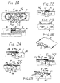
- Fig. 14 shows still a further embodiment of drive mechanism 66 using a motor 67 driving a toothed belt 68 which is wrapped around rotatable spar sections 10 and meshes with teeth on the latter. Idler pulleys 69 are provided to tension the belt and to hold the latter into good driving contact with the sprocket on motor 67.
- the drive mechanisms 66 are mounted on the ribs 6 which hold the rotatable spar sections 10.
- Fig. 14 also shows a locking mechanism 70 which rigidly locks the rotatable and non-rotatable spar sections together.
- Locking mechanism 70 comprises a pair of tapered pins 71 projecting from opposite sides of an actuator 72, and these pins are forced into aligned holes 73 in the overlapping portions of spar sections 9 and 10.
- Fig. 15 is a cross-sectional view showing the toothed belt 68 passing over the rotatable spar section 10 directly behind the bearing 30.
- Drive mechanism 66 has the desirable advantage of being somewhat more compact and lighter in weight than the drive mechanism 60 of Fig. 13, but still has all the functional advantages of the latter.
- Locking mechanism 70 has the desirable feature of positively locking the rotatable and non-rotatable spar sections together so that there can be no relative movement between them in either the extended or retracted condition, which is particularly advantageous in the extended condition.
- a locking device such as 70 could also be used on the embodiments shown in Figs. 16, 18, 20 and 22.
- Fig. 16 shows a retracted wing of the configuration in which the outer spar sections telescope into the interior of the inner spar sections, and the outer skin sections telescope over the inner skin sections.
- Fig. 16 also shows interlocking formations 73 at the inner ends of the skin sections 5, which extend around the entire wing profile. These formations 73 fit snugly over the next inside skin section and slide freely thereover when the wing is being extended or retracted.
- each spar section carries the load of its respective wing section as well as the accumulated loads of all outboard spar sections, and ach spar section transfers its load to the next inboard spar section.
- Figs. 18 and 19 are similar to Figs. 16 and 17, respectively, except that in this case, the outer spar sections 9, 10 telescope over the inner spar sections, and the outer skin sections 5 telescope into the interior of the inner skin sections. Accordingly, the ribs 6 are attached to the inner ends of the spar sections 9 and 10, and the spar disks 33 and 34 are attached to the outer ends of the spar sections. In like manner, the formations 73 are attached to the outer ends of the skin sections, and their respective flanges 74 are attached to the ribs 6 at the inner ends of the skin sections.
- the central housing 1 has a laterally extending cover 75, which forms an enclosed compartment in which the retracted wing is contained, the said compartment being closed by end plates 76 at the outer ends of each of the outer wing sections.
- Fig. 19 is a fragmentary sectional view of the wing of Fig. 18 in the extended condition, showing the interlocking engagement of the formation 73 with its associated flange 74.
- Figs. 20 and 21 are also similar to Figs. 16 and 17 in the respect that the outer spar sections telescope into the inner spar sections, but differ in that the rigid skin sections 5 of Figs. 16, 17 have been replaced by a continuous flexible skin 5′ that is attached to all of the ribs 6′.
- the ribs 6′ are cut away on their inner sides to provide cavities into which the folds of flexible skin material are received when the wing is retracted, as shown in Fig. 20.
- this embodiment of the invention has a cover 75′ extending laterally from the central housing 1, and this is closed by an end plate 76′. Since the retracted wing of Fig. 20 does not have the attached rigid skin sections on top of the spar sections, as in Figs.
- the complete profile height of the enclosure formed by cover 75 can be utilized to store a larger number of spar sections, which would allow for a longer wing span.
- the flexible skin 5′ allows for a greater disparity between the profile of the outer wing section and the inner root section, permitting use of tapered wing plans or variations in the profile from root to tip.
- the flexible skin 5′ is more economical to produce than the rigid skin sections 5 of the earlier embodiments, and its lack of discontinuities makes for smoother laminar flow of air over the wing. The lack of discontinuities in the skin is clearly shown in Fig. 21.
- FIGs. 22 and 23 are enlarged fragmentary sectional views through a portion of one rib and the skins of two wing sections in the extended wing condition, showing the interlocking relationship between formation 73 and flange 74.
- Flange 74 is seen to have an inwardly turned portion 77 that lies against the side of rib 6 and is attached thereto at 78 by rivets or other suitable connectors.
- Figs. 24 and 25 show another embodiment of the interlock arrangement between the skin 5 of one wing section and the skin of an adjoining section.
- the skins 5 are provided on their inner surfaces with a plurality of spaced-apart, span-wise extending stiffeners, which form channels 80 beteeen them.
- An L-shaped bracket 81 is attached to rib 6, and has a flange 82 that fits over and interlocks with the tapered inside edge of formation 73. Bracket 81 also has an inwardly turned portion 83 that lies against the side of rib 6, and is attached thereto at 84. The virtue of this arrangement is that it stiffens the skin considerably.
- Fig. 26 is a fragmentary perspective view of one wing skin 5, showing the channels 80 in the interior surface, as well as the interlocking formation 73 at the end of the skin section.
- Figs. 27 and 28 show still another embodiment of the interlock arrangement between the skin 5 of one wing section and the skin of an adjoining section.
- the interlock member attached to the side of rib 6 is designated by the reference numeral 85 and has a T-shaped cross section, with a horizontal top flange 86 and vertical flange 87.
- Top flange 86 is interrupted at regularly spaced intervals and is undercut to form slots 88.
- Extending down into the gaps formed by the interruptions in top flange 86 are stiffeners 89 that are attached to the inside surface of the skin 5 and extend in the span-wise direction.
- the stiffeners 89 each has a flange 90 on its bottom surface that extends laterally into the undercut slot 88.
- the top flanges 86 thus interlock with the C-shaped channels 91, which prevents separation of the skins 5 at all times during extension and retraction of the wings, instead of only at the fully extended condition, as in the case of the embodiment of Figs. 22, 23 and Figs. 24, 25.
- Fig. 29 is a fragmentary perspective view of the rear portion of an extended wing, showing one aileron and a portion of the associated flap, both of which telescope with the wing section, while Fig. 30 is a partially cutaway view of one section of the aileron.
- the wing construction is of the type wherein the outer wing sections 4 telescope into the interior of the inner wing sections, and likewise, the outer aileron sections 14 telescope into the inner aileron sections.
- the aileron sections 14 also telescope into the flap sections 15. As best shown in Fig.
- the aileron sections 14 each comprise a top skin 92 and bottom skin 93 which are joined together at their rear edges, and are connected at their forward edge by inwardly turned walls 94 that are joined to a tubular portion 95.
- the tubular portion 95 is closed at one end by an end wall 96, and the other end is connected to a rib 97, which is attached to the top and bottom skins 92 and 93.
- the rib end of one aileron section telescopes into the open end of the adjoining inner section, so that rotational movement of one section causes all of the aileron sections to rotate as onw.
- each wing section 4 Attached to the open outer end of each wing section 4 at the rear edge thereof is a rearwardly projecting bearing support member 98 that extends through the opening in the tubular portion 95 between the walls 94, and has a bearing 99 supporting the tubular portion.
- the bearing 99 thus defines the rotational axis F--F of the aileron sections 14. Rotational movement of aileron sections 14 about the axis of bearing 99, as indicated by the arrow E, is accomplished by means of a telescopic drive mechanism 100, shown schematically in Fig. 29, which might be similar to the mechanisms shown in Figs. 11 or 12.
- Fig. 31 is a view similar to Fig. 29, but showing another embodiment of the aileron skin and drive arrangement, wherein the telescopic drive tube for operating the aileron is contained within the wing sections.
- the ailerons are here designated by the reference numeral 14′, and are constructed, as best shown in Fig. 32, with a top skin 101 and bottom skin 102 which are joined together at their rear edges, and connected at their forward edge by a wall 103.
- the aileron 14′ is open at one end, and is closed at the other end by a rib 104.
- the wall 103 has a forwardly bent flange 105 at one end, through which a rotational axis G--G extends, and projecting from flange 105 radially with respect to axis G--G is a tab 106, which is attached to any suitable motion-transmitting means connecting the aileron to a telescopic tubular drive shaft 107 inside the wing sections 4.
- the aileron 14′ of Fig. 32 is of slightly different configuration than the aileron 14 of Fig. 31, but such differences are immaterial, as they function in the same manner.
- Flange 105 is connected to another flange 108 projecting rearwardly from the trailing edge of the wing section 4, by suitable bearing means (not shown) which allows rotational movement of the aileron about the axis G--G.
- the outer end section of the telescopic drive shaft 107 is rotationally supported by a bearing 109 on the outer end of its respective wing section 4, and the outer ends of the drive shaft sections are rotatably supported on their respective ribs by bearing means (not shown).
- the inner end of each aileron section is telescopically received within the adjacent inner aileron section, in the same manner that the wing sections 4 telescope.
- the motion-transmitting means 110 thus connects the outer aileron sections 14′ to the telescopic drive shaft 107 in a manner whereby rotation of the drive shaft causes the outer aileron section 14′ to rotate, and the latter, being telescopically interlocked with the other aileron sections, causes the aileron assembly to rotate as one.
- the advantage of this arrangement is that the aileron structure is much simpler than the one shown in Figs. 29 and 30.
- Fig. 33 shows an alternative split flap arrangement, which is probably the simplest flap arrangement that could be used with the telescopic wing.
- the trailing edge of the bottom skin of wing section 4 has a flat plate 111 hinged at 112, which can be raised and lowered by an actuator 113.
- the flat plate 111 can be lowered only when the wing is fully extended, and the plates 111 would be raised prior to retraction of the wing.
- This arrangement makes possible the simplest wing construction, providing an unbroken airfoil profile at the root section of the wing, into which the outer wing sections with ailerons can be retracted.
- the extended wing is retracted by causing the drive mechanism 32 to rotate in the appropriate direction, using either a motor or manually operated hand wheel.
- the rotating drive mechanism 32 turns the rotatable spar sections 10, which are located between pairs of non-rotatable spar sections 9, and this relative rotational movement between rotatable and non-rotatable spar sections, with their helical thread means of opposite hand at opposite ends, causes the spar sections to telescope together.
- the synchronous rotation of all of the rotatable spar sections causes each spar section, both rotatable and non-rotatable, to telescope with the adjacent inner spar section.
- Each spar section carries with its the associated rib and skin section, including their respective aileron and flap sections.
- the telescoped wing sections are either enclosed within the central housing or are placed in the area of the central housing, where they may occupy as little as 30% of the extended wing span, or even be enclosed entirely within the width of the fuselage. Due to the preloaded rolling element bushings between overlapping spar portions for a substantial distance, the spars retain their load-carrying capability throughout the entire range of extension and retraction.
- the spar sections may be telescoped into or over the adjoining inner spar section, and in like manner, the skin sections may telescope into or over the adjoining skin sections, as design considerations may dictate.
- the separate wing sections may be constructed with the skin and spar sections extending from opposite sides of the rib, or both extending from the same side of the rib.
- the drive mechanism 32 is rotated in the opposite direction, causing the spar sections to extend from the adjoining inner spar section, carrying their respective rib and skin sections with them.
- the terms “inner” and “outer” refer to span-wise directions, the term “inner” meaning toward the root en of the wing, or fuselage, and the term “outer” meaning toward the tip end of the wing.
- the term “thread means” as used in the claims refers to the thread-like helical grooves or channels formed in opposed surfaces of the overlapping spar sections, in which rolling elements such as ball bearings travel. The helical grooves are of right-hand direction at one end of each spar section, and of left-hand direction at the other end of the same spar section.
- thread means could include conventional threads, although such conventional threads are believed tobe less desirable than the rolling element bushing shown and described herein due to tolerance and frictional problems.
- the thread means connecting overlapping spar sections provides form-closed, interlocking connections which prevent any linear movement of spar sections relative to one another without relative rotation. With the form-closed connection it would be necessary to destroy the interlocking parts of the connection in order to realize relative linear movement between spar sections.
Landscapes
- Engineering & Computer Science (AREA)
- Mechanical Engineering (AREA)
- Aviation & Aerospace Engineering (AREA)
- Toys (AREA)
Applications Claiming Priority (2)
| Application Number | Priority Date | Filing Date | Title |
|---|---|---|---|
| US90545 | 1987-08-27 | ||
| US07/090,545 US4824053A (en) | 1987-08-27 | 1987-08-27 | Telescopic wing |
Publications (3)
| Publication Number | Publication Date |
|---|---|
| EP0304660A2 true EP0304660A2 (fr) | 1989-03-01 |
| EP0304660A3 EP0304660A3 (en) | 1990-04-11 |
| EP0304660B1 EP0304660B1 (fr) | 1992-06-17 |
Family
ID=22223256
Family Applications (1)
| Application Number | Title | Priority Date | Filing Date |
|---|---|---|---|
| EP88112193A Expired EP0304660B1 (fr) | 1987-08-27 | 1988-07-28 | Aile téléscopique |
Country Status (3)
| Country | Link |
|---|---|
| US (1) | US4824053A (fr) |
| EP (1) | EP0304660B1 (fr) |
| DE (1) | DE3872106T2 (fr) |
Cited By (4)
| Publication number | Priority date | Publication date | Assignee | Title |
|---|---|---|---|---|
| AU712145B2 (en) * | 1993-08-26 | 1999-10-28 | David E. Gevers | Multi-purpose aircraft |
| EP3287363A1 (fr) * | 2016-08-24 | 2018-02-28 | Airbus (S.A.S.) | Extension de voilure pour une aile d'aeronef |
| CN111688913A (zh) * | 2020-05-26 | 2020-09-22 | 哈尔滨工业大学 | 一种双驱动可变展长与上下反角的机翼 |
| CN112455652A (zh) * | 2020-12-08 | 2021-03-09 | 吉林大学 | 一种多级伸缩缸结构及伸缩缸式折叠机翼 |
Families Citing this family (62)
| Publication number | Priority date | Publication date | Assignee | Title |
|---|---|---|---|---|
| US5645250A (en) * | 1993-08-26 | 1997-07-08 | Gevers; David E. | Multi-purpose aircraft |
| US6047923A (en) * | 1995-01-13 | 2000-04-11 | Trimbach Turbine, Ltd. | Aircraft having multiple fuselages |
| US6892979B2 (en) * | 2002-09-11 | 2005-05-17 | Karl F. Milde, Jr. | VTOL personal aircraft |
| US6910661B2 (en) * | 2002-10-10 | 2005-06-28 | The Boeing Company | Geometric morphing wing |
| US7195210B2 (en) * | 2002-10-10 | 2007-03-27 | The Boeing Company | Fiber matrix for a geometric morphing wing |
| US7530315B2 (en) | 2003-05-08 | 2009-05-12 | Lone Star Ip Holdings, Lp | Weapon and weapon system employing the same |
| US6834835B1 (en) | 2004-03-12 | 2004-12-28 | Qortek, Inc. | Telescopic wing system |
| US20060144992A1 (en) * | 2004-12-07 | 2006-07-06 | Jha Akhllesh K | Transformable fluid foil with pivoting spars |
| US7296529B2 (en) * | 2005-09-08 | 2007-11-20 | Bereli M. Lazar | Fluidynamic lift combined array, technology |
| US7895946B2 (en) * | 2005-09-30 | 2011-03-01 | Lone Star Ip Holdings, Lp | Small smart weapon and weapon system employing the same |
| US7690304B2 (en) | 2005-09-30 | 2010-04-06 | Lone Star Ip Holdings, Lp | Small smart weapon and weapon system employing the same |
| US20090206193A1 (en) * | 2006-06-09 | 2009-08-20 | File David J | Ballistically deployed telescoping aircraft wing |
| US7931240B2 (en) * | 2006-08-11 | 2011-04-26 | Techno-Sciences, Inc. | Cellular support structures used for controlled actuation of fluid contact surfaces |
| US8541724B2 (en) | 2006-09-29 | 2013-09-24 | Lone Star Ip Holdings, Lp | Small smart weapon and weapon system employing the same |
| US8117955B2 (en) | 2006-10-26 | 2012-02-21 | Lone Star Ip Holdings, Lp | Weapon interface system and delivery platform employing the same |
| US8439314B1 (en) | 2006-11-06 | 2013-05-14 | Sanjay Dhall | Aircraft having offset telescopic wings |
| US7762500B1 (en) | 2006-11-06 | 2010-07-27 | Sanjay Dhall | Telescopic wing with articulated structural spar |
| US7798443B2 (en) * | 2006-12-18 | 2010-09-21 | The Boeing Company | Composite material for geometric morphing wing |
| US7789343B2 (en) * | 2007-07-24 | 2010-09-07 | The Boeing Company | Morphing aircraft with telescopic lifting and control surfaces |
| US7832690B1 (en) | 2008-02-12 | 2010-11-16 | Mundus Group, Inc. | Telescoping wing locking system |
| DE102008020390A1 (de) * | 2008-04-23 | 2009-11-05 | Airbus Deutschland Gmbh | Tragflügel für ein Luftfahrzeug |
| US8157206B2 (en) * | 2008-06-11 | 2012-04-17 | Icon Aircraft, Inc. | Two-motion wing-fold mechanism with independent load path |
| US8360356B2 (en) * | 2008-07-17 | 2013-01-29 | W. Eric Moore | Flying apparatus |
| US20100041778A1 (en) * | 2008-08-14 | 2010-02-18 | Composite Technology Development, Inc. | Reconfigurable polymeric foam structure |
| US8336830B2 (en) * | 2008-10-03 | 2012-12-25 | The Boeing Company | Retractable aircraft wing tip |
| US20100148011A1 (en) * | 2008-11-12 | 2010-06-17 | Sanderson Terry M | Telescoping structure and method |
| US8262032B2 (en) * | 2008-11-13 | 2012-09-11 | Raytheon Company | Collapsible wing beams and method |
| GB201018185D0 (en) * | 2010-10-28 | 2010-12-08 | Airbus Operations Ltd | Wing tip device attachment apparatus and method |
| US9068803B2 (en) | 2011-04-19 | 2015-06-30 | Lone Star Ip Holdings, Lp | Weapon and weapon system employing the same |
| US9290260B2 (en) | 2011-10-01 | 2016-03-22 | The Boeing Company | Wing fold controller |
| US9211946B2 (en) | 2011-10-01 | 2015-12-15 | The Boeing Company | Wing fold system with latch pins through multiple mating lugs |
| US9296469B2 (en) | 2011-10-01 | 2016-03-29 | The Boeing Company | Horizontal folding wingtip |
| US10538307B2 (en) | 2011-10-01 | 2020-01-21 | The Boeing Company | Hinged raked wing tip |
| US9499252B2 (en) | 2011-10-01 | 2016-11-22 | The Boeing Company | Wing fold controller |
| US9156559B2 (en) | 2011-10-19 | 2015-10-13 | The Boeing Company | Segmented aircraft wing having solar arrays |
| IL216345A (en) * | 2011-11-14 | 2017-09-28 | Israel Aerospace Ind Ltd | Wing and the devices for it |
| US8733692B2 (en) * | 2012-06-11 | 2014-05-27 | The Boeing Company | Latching apparatus and methods |
| US9415857B2 (en) | 2012-10-30 | 2016-08-16 | The Boeing Company | Wing fold system |
| US9469392B2 (en) | 2012-10-30 | 2016-10-18 | The Boeing Company | Wing fold system rotating latch |
| US9481446B2 (en) | 2012-10-30 | 2016-11-01 | The Boeing Company | System for latching and locking a foldable airfoil |
| US9469391B1 (en) | 2013-04-26 | 2016-10-18 | The Boeing Company | Adaptive wing for an aircraft |
| US10099770B2 (en) * | 2013-07-26 | 2018-10-16 | Icon Aircraft, Inc. | Manuel wing-fold mechanism |
| US9296471B2 (en) * | 2013-10-06 | 2016-03-29 | The Boeing Company | Swing wing tip system, assembly and method with dual load path structure |
| US9139284B1 (en) | 2013-10-16 | 2015-09-22 | Sanjay Dhall | Telescopic wing with rotating structural spar |
| US10081424B2 (en) | 2013-12-31 | 2018-09-25 | Bogdan Radu | Flying car or drone |
| US9522725B2 (en) * | 2014-02-13 | 2016-12-20 | Northrup Grumman Systems Corporation | Stowable and deployable unmanned aerial vehicle |
| US9457887B2 (en) * | 2014-03-05 | 2016-10-04 | Toyota Motor Engineering & Manufacturing North America, Inc. | Smart material trailing edge variable chord morphing wing |
| CA2961872A1 (fr) * | 2014-09-25 | 2016-03-31 | Bombardier Inc. | Revetement adaptable pour un aeronef |
| US11027584B1 (en) * | 2015-07-22 | 2021-06-08 | Taras Kiceniuk, Jr. | Flying car with fore and aft lifting surfaces |
| US12122203B1 (en) * | 2014-10-17 | 2024-10-22 | Taras Kuciniek, Jr. | Flying car with multiple wheels |
| WO2016122486A1 (fr) * | 2015-01-28 | 2016-08-04 | Mccoy Jeremiah | Aile télescopique |
| DE112018006890T5 (de) | 2018-01-18 | 2020-10-01 | Fleck Future Concepts Gmbh | Platz-effizient verstaubarer, automatisch bedienbarer, verdichtbarer Flugzeugflügel |
| US11370526B2 (en) * | 2018-05-31 | 2022-06-28 | Airbus Operations Gmbh | Latching device for a wing arrangement for an aircraft |
| US11319054B2 (en) * | 2018-05-31 | 2022-05-03 | Airbus Operations Gmbh | Wing arrangement for an aircraft |
| US11214353B2 (en) * | 2018-06-01 | 2022-01-04 | Airbus Operations Gmbh | Wing arrangement for an aircraft and aircraft |
| EP3587252A1 (fr) * | 2018-06-28 | 2020-01-01 | Airbus Operations GmbH | Système d'arrêt pour arrêter un premier composant d'aéronef par rapport à un second composant d'aéronef |
| US11254412B2 (en) | 2019-03-29 | 2022-02-22 | The Boeing Company | Foldable raked wing tips having aerodynamic devices |
| US11591076B2 (en) * | 2019-06-26 | 2023-02-28 | Toyota Motor Engineering & Manufacturing North America, Inc. | Inflatable drone with shape memory alloy wires |
| AU2021209412A1 (en) * | 2020-01-23 | 2022-07-14 | Bae Systems Plc | Airframe and method for assembling an airframe |
| US12358332B1 (en) | 2023-03-04 | 2025-07-15 | Makeeva Spann | Vertical takeoff and landing personal land to air vehicle |
| CN116373923A (zh) * | 2023-04-19 | 2023-07-04 | 中车青岛四方车辆研究所有限公司 | 高速列车无级伸缩式升力翼 |
| US12605978B1 (en) * | 2024-10-18 | 2026-04-21 | Taras Kuciniek, Jr. | Flying car with multiple wheels |
Family Cites Families (5)
| Publication number | Priority date | Publication date | Assignee | Title |
|---|---|---|---|---|
| US2056188A (en) * | 1934-08-17 | 1936-10-06 | Kenneth L Hayden | Aircraft wing construction |
| US2423095A (en) * | 1944-01-27 | 1947-07-01 | Thomas F Gibson | Variable area wing |
| US2743072A (en) * | 1953-08-11 | 1956-04-24 | Emmi Joseph | Collapsible wing system for aircraft and actuating means therefor |
| US3851978A (en) * | 1973-09-12 | 1974-12-03 | S Kuipers | Turnbuckle |
| US4706907A (en) * | 1985-01-29 | 1987-11-17 | Eduard Kopylov | Aircraft |
-
1987
- 1987-08-27 US US07/090,545 patent/US4824053A/en not_active Expired - Lifetime
-
1988
- 1988-07-28 EP EP88112193A patent/EP0304660B1/fr not_active Expired
- 1988-07-28 DE DE8888112193T patent/DE3872106T2/de not_active Expired - Lifetime
Cited By (6)
| Publication number | Priority date | Publication date | Assignee | Title |
|---|---|---|---|---|
| AU712145B2 (en) * | 1993-08-26 | 1999-10-28 | David E. Gevers | Multi-purpose aircraft |
| EP3287363A1 (fr) * | 2016-08-24 | 2018-02-28 | Airbus (S.A.S.) | Extension de voilure pour une aile d'aeronef |
| FR3055307A1 (fr) * | 2016-08-24 | 2018-03-02 | Airbus | Extension de voilure pour une aile d'aeronef |
| CN111688913A (zh) * | 2020-05-26 | 2020-09-22 | 哈尔滨工业大学 | 一种双驱动可变展长与上下反角的机翼 |
| CN112455652A (zh) * | 2020-12-08 | 2021-03-09 | 吉林大学 | 一种多级伸缩缸结构及伸缩缸式折叠机翼 |
| CN112455652B (zh) * | 2020-12-08 | 2022-07-01 | 吉林大学 | 一种多级伸缩缸结构及伸缩缸式折叠机翼 |
Also Published As
| Publication number | Publication date |
|---|---|
| DE3872106D1 (de) | 1992-07-23 |
| EP0304660B1 (fr) | 1992-06-17 |
| US4824053A (en) | 1989-04-25 |
| DE3872106T2 (de) | 1992-12-03 |
| EP0304660A3 (en) | 1990-04-11 |
Similar Documents
| Publication | Publication Date | Title |
|---|---|---|
| US4824053A (en) | Telescopic wing | |
| US7762500B1 (en) | Telescopic wing with articulated structural spar | |
| EP1794051B1 (fr) | Systeme compact d'actionnement de pylone pour aeronef convertible | |
| EP3056425B1 (fr) | Aeronef pouvant decoller a la verticale | |
| EP3575203B1 (fr) | Aile d'aéronef et dispositif d'embout d'aile | |
| DE102014213215A1 (de) | Senkrechtstarter | |
| US8424801B2 (en) | Slat support assembly | |
| US20160040595A1 (en) | Adjustable size inlet system | |
| US8439314B1 (en) | Aircraft having offset telescopic wings | |
| US3904152A (en) | Variable area, variable camber wing for aircraft | |
| US8459948B2 (en) | Retractable composite rotor blade assembly | |
| US20180327077A1 (en) | Telescoping wing | |
| US6454532B1 (en) | Harmonic drive system for the retraction/extension of variable diameter rotor systems | |
| US6655915B2 (en) | Drive system for the retraction/extension of variable diameter rotor systems | |
| US20180072410A1 (en) | Vtol rotor assembly with stowable blades | |
| US20240166344A1 (en) | An aircraft, in particular a personal air mobility aircraft or drone, an annular propeller unit, and a boat comprising this unit | |
| EP1460258B1 (fr) | Tuyère déployable d'un moteur de fusée | |
| EP4185502B1 (fr) | Moteur pour un aéronef, procédé de fonctionnement d'un moteur pour un aéronef, et aéronef comportant au moins un moteur | |
| DE102004008073B4 (de) | Ausfahrtriebwerk | |
| DE602004005602T2 (de) | Starrer flügel mit variablem auftrieb aufgrund des ausklappens eines flexiblen flügels | |
| WO2017076498A1 (fr) | Aéronef à voilures gonflables enroulées à l'intérieur du fuselage | |
| CN115743533A (zh) | 一种倾转旋翼无人机结构及其使用方法 | |
| WO2017076499A1 (fr) | Aéronef | |
| CN114872881B (zh) | 一种大行程可伸缩机翼及无人机 | |
| US9586674B2 (en) | Collapsible airfoil spooled retractable rotor |
Legal Events
| Date | Code | Title | Description |
|---|---|---|---|
| PUAI | Public reference made under article 153(3) epc to a published international application that has entered the european phase |
Free format text: ORIGINAL CODE: 0009012 |
|
| AK | Designated contracting states |
Kind code of ref document: A2 Designated state(s): DE FR GB |
|
| PUAL | Search report despatched |
Free format text: ORIGINAL CODE: 0009013 |
|
| AK | Designated contracting states |
Kind code of ref document: A3 Designated state(s): DE FR GB |
|
| 17P | Request for examination filed |
Effective date: 19900331 |
|
| 17Q | First examination report despatched |
Effective date: 19910326 |
|
| GRAA | (expected) grant |
Free format text: ORIGINAL CODE: 0009210 |
|
| AK | Designated contracting states |
Kind code of ref document: B1 Designated state(s): DE FR GB |
|
| REF | Corresponds to: |
Ref document number: 3872106 Country of ref document: DE Date of ref document: 19920723 |
|
| ET | Fr: translation filed | ||
| PLBE | No opposition filed within time limit |
Free format text: ORIGINAL CODE: 0009261 |
|
| STAA | Information on the status of an ep patent application or granted ep patent |
Free format text: STATUS: NO OPPOSITION FILED WITHIN TIME LIMIT |
|
| 26N | No opposition filed | ||
| PGFP | Annual fee paid to national office [announced via postgrant information from national office to epo] |
Ref country code: GB Payment date: 19990614 Year of fee payment: 12 |
|
| PGFP | Annual fee paid to national office [announced via postgrant information from national office to epo] |
Ref country code: FR Payment date: 19990616 Year of fee payment: 12 |
|
| PG25 | Lapsed in a contracting state [announced via postgrant information from national office to epo] |
Ref country code: GB Free format text: LAPSE BECAUSE OF NON-PAYMENT OF DUE FEES Effective date: 20000728 |
|
| GBPC | Gb: european patent ceased through non-payment of renewal fee |
Effective date: 20000728 |
|
| PG25 | Lapsed in a contracting state [announced via postgrant information from national office to epo] |
Ref country code: FR Free format text: LAPSE BECAUSE OF NON-PAYMENT OF DUE FEES Effective date: 20010330 |
|
| REG | Reference to a national code |
Ref country code: FR Ref legal event code: ST |
|
| PGFP | Annual fee paid to national office [announced via postgrant information from national office to epo] |
Ref country code: DE Payment date: 20070926 Year of fee payment: 20 |