EP0304736B1 - Procédé et dispositif pour envelopper spécialement des paquets de cigarettes - Google Patents
Procédé et dispositif pour envelopper spécialement des paquets de cigarettes Download PDFInfo
- Publication number
- EP0304736B1 EP0304736B1 EP88113100A EP88113100A EP0304736B1 EP 0304736 B1 EP0304736 B1 EP 0304736B1 EP 88113100 A EP88113100 A EP 88113100A EP 88113100 A EP88113100 A EP 88113100A EP 0304736 B1 EP0304736 B1 EP 0304736B1
- Authority
- EP
- European Patent Office
- Prior art keywords
- packs
- blanks
- folding turret
- web
- cigarette
- Prior art date
- Legal status (The legal status is an assumption and is not a legal conclusion. Google has not performed a legal analysis and makes no representation as to the accuracy of the status listed.)
- Expired - Lifetime
Links
Images


Classifications
-
- B—PERFORMING OPERATIONS; TRANSPORTING
- B65—CONVEYING; PACKING; STORING; HANDLING THIN OR FILAMENTARY MATERIAL
- B65B—MACHINES, APPARATUS OR DEVICES FOR, OR METHODS OF, PACKAGING ARTICLES OR MATERIALS; UNPACKING
- B65B41/00—Supplying or feeding container-forming sheets or wrapping material
- B65B41/02—Feeding sheets or wrapper blanks
- B65B41/10—Feeding sheets or wrapper blanks by rollers
-
- B—PERFORMING OPERATIONS; TRANSPORTING
- B65—CONVEYING; PACKING; STORING; HANDLING THIN OR FILAMENTARY MATERIAL
- B65B—MACHINES, APPARATUS OR DEVICES FOR, OR METHODS OF, PACKAGING ARTICLES OR MATERIALS; UNPACKING
- B65B11/00—Wrapping, e.g. partially or wholly enclosing, articles or quantities of material, in strips, sheets or blanks, of flexible material
- B65B11/06—Wrapping articles, or quantities of material, by conveying wrapper and contents in common defined paths
- B65B11/28—Wrapping articles, or quantities of material, by conveying wrapper and contents in common defined paths in a curved path, e.g. on rotary tables or turrets
- B65B11/30—Wrapping articles, or quantities of material, by conveying wrapper and contents in common defined paths in a curved path, e.g. on rotary tables or turrets to fold the wrappers in tubular form about contents
- B65B11/32—Wrapping articles, or quantities of material, by conveying wrapper and contents in common defined paths in a curved path, e.g. on rotary tables or turrets to fold the wrappers in tubular form about contents and then to form closing folds of similar form at opposite ends of the tube
Definitions
- the invention relates to a method for wrapping packs, in particular cuboid cigarette packs, in blanks which are placed around the packs in a U-shape when the packs are inserted into pockets of a folding turret and the projecting tabs are then folded, the folding turret being provided with several, in particular two Packs are fed in parallel next to each other and the blanks are separated from a common material web and conveyed into the movement path of the packs in the correct position. Furthermore, the invention relates to a device according to the preamble of claim 6 (such a method and such a device are known from EP-A-0 135 818).
- Cigarette packs are mostly provided with an outer wrapping made of a thin film.
- the invention is primarily concerned with the manufacture of the outer wrapper for cigarette packs.
- Packaging machines for the outer wrapping of cigarette packs must be very efficient, in accordance with the high performance of the upstream packaging machines for the manufacture of the cigarette packs.
- a packaging machine for producing cigarette packs is known, in which successive cigarette packs are fed in the radial direction to a folding turret. At the same time, two packs are fed side by side in the axial direction.
- the folding turret provided has particularly large dimensions in the axial direction. Folding elements arranged on the circumference of the folding turret must have a correspondingly wide design.
- the object of the method and the device according to the invention is to ensure a reliable and simple process of transferring the packs to the folding turret with a "normal" axial length of the folding turret.
- the method according to the invention is characterized in that the packs - relative to the folding turret - are kept ready next to one another in a common, transverse axial plane and in the circumferential direction and are pushed into the corresponding pockets of the folding turret in this plane.
- the device according to the invention is characterized in that the pockets for receiving the packs to be supplied next to one another are arranged in the folding turret in a transverse axial plane and parallel to one another in the circumferential direction.
- the material web is fed to the wrapping station in sections, namely in each case in the dimension of two sections corresponding to web sections.
- the blanks are in the path of movement of the cigarette packs held ready, directed transversely to them.
- the conveyor elements for feeding the material web are designed as a conveyor roller, at least one of these conveyor rollers being a knife roller which produces the web section and the blanks by means of a precise separating cut.
- a conveyor roller is assigned to a cigarette pack or a movement path of the same.
- These conveyor rollers are provided with a central, slot-shaped passage through which the packs are pushed, taking the blanks held on the jacket of the conveyor rollers.
- the objects to be packaged - in particular cigarette packs - are inserted from a sealed row of cigarette packs by a lifting movement, taking the blanks with them, into the pockets of the folding turret.
- Further features of the invention relate to the design of conveying and holding members for the material web and the cuts, to insertion members for the cigarette packs in the folding turret and to the design of the folding turret.
- the device shown as an exemplary embodiment in the drawings is particularly advantageously suitable for the production or for wrapping cuboid packs 10 in the form of cuboids.
- it is about the formation of an outer envelope 11 as cellophane, poly film or the like.
- the outer wrapper 11 consists of a rectangular blank 12 or 13. In a first folding step, this is placed around the cigarette pack 10 in a U-shape, forming a front one in the direction of movement Side wall 14. An overlap of correspondingly dimensioned side wall tabs 16 and 17 is formed in the longitudinal direction thereof on the further side wall 15 opposite this. These are connected to one another in the area of their overlap, in particular by sealing.
- the first side end flaps 20 and 21 are folded in an extension of the side wall flaps 16, 17 against the bottom wall and end wall of the cigarette pack 10.
- trapezoidal longitudinal tabs 22, 23 are folded against one another with an overlap to complete bottom wall 18 and end wall 19.
- the cigarette packs 10 to be wrapped in this way come from a packaging machine (not shown).
- the cigarette packs 10 are conveyed in a sealing position next to one another on a packing track 24.
- This consists of a lower wall 25, an upper wall 26 and side guides 27.
- the cigarette packs 10 are conveyed in cycles by transferring the feed from one cigarette pack 10 to the other.
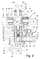
- the cigarette packs 10 are transferred to a folding turret 29, which rotates step by step in the vertical plane, by lifting them off the packing track 24 and moving upwards.
- the folding turret 29 is provided with pockets 30, 31 arranged in pairs.
- a cigarette packet 10 is inserted from below into the pockets 30, 31, which are open on the radially outer side, with the taking of a correspondingly provided blank 12, 13, which wraps itself around the U-shape Cigarette pack 10 around, starting from the side wall 14 lying forward in the direction of movement.
- the cigarette packs 10 are conveyed in cycles along a three-quarter circle, by carrying out the folding operations described.
- the cigarette packs 10 provided with the finished outer wrapper 11 are again pushed out in pairs from the pockets 30, 31 and inserted into a discharge conveyor 33.
- a double slide 34 is arranged in the region of the insertion station 28, with two plungers 35, 36 arranged at a distance from one another and moving together.
- a support body 37 common for the tappets 35, 36 is driven up and down in a suitable manner, in the present case via a rocker arm 38 with a link 39.
- the plungers 35, 36 pass through slot-shaped recesses 40, 41 in the lower wall 25 of the packing web 24.
- the plungers 35, 36 are arranged at such a distance from one another that a distance corresponding to the dimensions of two cigarette packs 10 is formed between the two cigarette packs 10 lifted out of a sealing row 42 of the cigarette packs 10.
- a sufficient distance is produced between the cigarette packs 10 to be wrapped in order for the two blanks 12 and 13 to be carried along and for the folding steps to be carried out in the region of the folding turret 29.
- the cigarette packs 10 are conveyed with the blanks 12, 13 through the plungers 35, 36 to their end position within the pockets 30, 31. After returning to the starting position (flush with bottom wall 25), the sealing row 42 of the cigarette packs 10 conveyed further by a path corresponding to the dimension of two cigarette packs 10, so that a continuous row of seals 42 is created, bearing against an end wall 43 of the pack web 24.
- the subsequent part of the sealing row 42 is prevented from moving further, namely by clamping forward-lying cigarette packs 10 to the upper wall 26 of the packing web 24.
- a partial region of the lower wall 25 is designed as a lifting plate 44.
- the two front cigarette packs 10 are clamped by a slight upward movement and thus the sealing row 42 is fixed.
- the blanks 12 and 13 are each held in a position exactly above the two upwardly moving cigarette packs 10 in a plane transverse to their path of movement.
- the cigarette packs 10 exit through an ejection opening 45, 46 of the top wall 26.
- the blanks 12, 13 are kept ready above this ejection opening 45, 46.
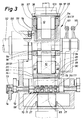
- the two blanks 12, 13, each associated with a cigarette pack 10, are separated from a common, continuous material web 47 made of packaging material (film).
- the material web 47 drawn off in sections from a bobbin, not shown, is fed to the insertion station 28 essentially horizontally, at least transversely to the upward movement path of the cigarette packs 10.
- Two driven and correspondingly controlled pull rollers 48, 49 ensure the precise feed.
- the material web 47 then runs over a plurality of conveyor rollers which can be driven in rotation. Of these, one adjoining the pulling rollers 48, 49 is designed as a knife roller 50 with a revolving separating knife 51 and a fixed counter knife 52.
- the knife roller 50 is dimensioned such that in connection with a corresponding relative position a separating cut 53 for separating the two blanks 12 and 13 from one another and then a further separating cut 54 for separating the (second) cut 13 from the material web 47 are made at a suitable point by the separating knife 51 and counter knife 52.
- the knife drum 50 is provided with suction bores 55 which fix the front, free end of the subsequent material web 47 on the knife drum 50 by means of suction air.
- the material web 47 is conveyed during each work cycle by a web section corresponding to the dimensions of the two blanks 12 and 13.
- the cuts 12, 13 and the separation from the material web 47 take place during the transport.
- the material web 47 or the cuts 12, 13 are transferred directly to the circumference of further roller-shaped conveying members which transfer the material web 47 convey under strong wraps into the folded position (Fig. 4).
- Roller conveyors 56 and 57 in the area of the insertion station 28 also serve as holding members for the blanks 12, 13 in exact relative position to the upward movement path of the cigarette packs 10.
- the blanks 12, 13 become from these roller conveyors 56, 57 during the upward movement of the cigarette packs 10 slipping pulled off.
- the roller conveyors 56, 57 consist of lateral, rotatably drivable suction disks 58, 59. These are each provided on the outside with drivable shaft journals 60.
- the suction disks 58, 59 are dimensioned in their axial direction and spaced apart such that only edge strips of the material web 47 or the blanks 12, 13 lie on the circumference of the suction disks 58, 59 and are held by suction air. This edge strip corresponds to the width of parts of the blanks 12, 13 projecting beyond the cigarette pack 10 during this phase for the later formation of the bottom wall 18 and end wall 19.
- Upright support walls 61, 62 and 63, 64 are formed between the lateral suction disks 58, 59. These are assigned in pairs to the suction disks 58, 59 as a fixed, immovable addition to the roller conveyors 56, 57.
- the support walls 61..64 are designed such that a gap-shaped passage opening 65, 66 is formed in the continuation of the ejection openings 45, 46 for the passage of the cigarette packs 10.
- the support walls 61..64 are connected to the upper wall 26 of the packing web 24 or form part of the same.
- the support walls 61..64 are shaped in such a way that the blanks 12, 13 rest in the region of the same on rounded or arched outer surfaces.
- the support walls 61..64 are adapted to the cylindrical shape as part of the roller conveyors 56, 57.
- the adjacent support walls 62, 63 flow smoothly into an arcuate guide trough 67 of the correspondingly shaped upper side of the upper wall 26.
- the material web 47 or the blanks 12, 13 are conveyed through this guide trough 67, bearing against corresponding guide surfaces.
- the blanks 12, 13 are fixed on the roller conveyors 56, 57 or the suction disks 58, 59 thereof in such a way that there is a slight eccentricity in relation to the associated cigarette packs 10.
- the cigarette packs 10 are thereby fed into the pockets 30, 31 with unevenly long, downward-facing side wall tabs 16, 17.
- a further guiding and conveying element is arranged between the roller conveyors 56, 57, namely in the region of the guiding trough 67.
- this consists of a guide roller 68 which is driven in rotation with the cycle of the other conveying members and which is mounted centrally in the guide trough 67.
- the guide roller 68 is provided with a plurality of parallel rotations 69 running all around.
- a plurality of roller sections 70 arranged at a distance from one another in the axial direction are provided for the contact of the material web 47.
- suction bore 71 opening on the peripheral surface, which fixes the material web 47 or the blanks 12, 13 on the roller sections 70.
- the suction bores 71 are connected to a central suction line 72 which is connected to a suction line connection 74 in the region of the rotary bearing of the guide roller 68 via a suction ring 73.
- a fixed counter body 75 is assigned to the guide roller 68. This is arranged centrally between the roller conveyors 56, 57. The lower area is arcuate and adapted to the dimensions of the guide roller 68.
- the counter body 75 is comb-like here with fingers 76, 77 directed towards both sides. These enter the indentations 69 between the roller sections 70 of the guide roller 68 and cause the material web 47 to be correctly guided during the feed movement, namely from the circumference of the first Transfer roller conveyor 56 to the guide roller 68 and is guided by this to the second roller conveyor 57.
- the counter body 75 also has a wiper function.
- the material web (47) or the blanks (12, 13) loop around the roller conveyors (56, 57) and the guide roller (68) by more than half.
- the separating cut (53) for dividing the two blanks (12, 13) lies from one another in the area of the guide roller (68), somewhat off-center, so that when the blanks (12, 13) are taken over by the associated cigarette packs (10), the blanks (12, 13) slip on the one hand from the roller conveyors (56, 57) and on the other hand, be pulled in opposite directions from the guide roller (68).
- the strongly curved course of the material web 47 or the blanks 12, 13 is particularly evident from FIG. 6.
- This shape of the material web 47 makes it possible to arrange the cigarette packs 10 to be pushed out together at a short distance from one another, despite the considerable dimensions of the blanks 12, 13 in the conveying direction.
- the arrangement of the conveyor rollers 50, 56, 57 and 68 relative to one another is such that the material web 47 is transferred directly from the circumference of one conveyor roller to the other.
- Each of these conveyor rollers is provided with radially directed suction bores 55 and 71 or 78 and 79, each of which grips an edge region of the material web 47 or of the blanks 12, 13 lying forward in the conveying direction and thus secures the transport.
- the suction bores When a blank 12, 13 is transferred from one of these conveyor rollers to the next, the suction bores momentarily come into an adjacent relative position (in FIG. 6 with the roller conveyor 56 and the guide roller 68). During the phase of the transition, the suction bore 78 holding the blank 13 up to that point is briefly vented, so that the blank is reliably transferred to the next conveyor roller.
- the roller conveyors 56, 57 are each provided with individual suction bores 78, 79 in the area of the suction disks 58, 59.
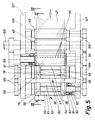
- the knife roller 50 is equipped with a row of suction bores 55 running through in the axial direction (FIG. 5).
- the system of suction bores is essentially designed in a conventional manner.
- the suction bores are axially parallel within the conveyor rollers Suction lines 80 connected. These open at the front ends of the conveyor rollers on non-rotatably mounted suction disks 81, shown in section in FIG. 5 by means of the roller conveyor 56.
- the suction disks 81 are each pressed by pressure springs 82 in a sliding and sealing manner against the facing end faces of the conveyor rollers.
- the suction disks 81 are also provided with circular suction grooves 83 which are open to the end faces of the conveyor rollers and with which the ends of the suction lines 80 temporarily overlap during the rotational movement of the conveyor rollers. Suction air is transmitted during this overlap phase.
- the length of the suction grooves 83 therefore corresponds to the duration of the suction phase.
- a vent hole 84 Adjacent to, but outside of, the suction grooves 83, a vent hole 84 is provided, where necessary, on the same circular arc as the suction grooves 83, so that the suction line 80 overlaps with the vent hole 84 during a brief phase of the rotational movement and thereby the already described ventilation of the suction bores causes.
- Fig. 7 shows the relative position of the suction grooves 83 and vent holes 84 for the conveyor rollers 50, 56, 57 and 68.
- the cigarette packs 10 with the blanks 12, 13 pass through a mouthpiece which passes through fixed outer walls 85, 86 on the one hand and through the correspondingly shaped counter body 75 on the other hand is formed.
- the cigarette packs 10 are held in the pockets 30, 31 formed by two pocket walls 87, 88 in such a way that the side wall tabs 16, 17 protrude from the pockets 30, 31.
- first folding members come into action, namely, side folders 89 and 90 which are arranged concentrically to the folding turret 29 and can be pivoted back and forth 89, the shorter, inner side wall tab 17 of the pockets 30 rearward in the direction of rotation of the folding turret 29 is first folded over.
- the inner side wall tab 17 of the adjacent pocket 31 is simultaneously folded over by a corresponding oscillating movement of the side folder 90.
- the folding turret 29 begins to rotate, the longer, outer side wall tab 16 of the pocket 31 is folded over by the edge of a stationary outer guide wall 91 of the folding turret 29.
- the corresponding side wall tab 17 of the cigarette pack 10 in the adjacent pocket 30 is folded in the same way by the side folder 90.
- the side folders 89, 90 mentioned are mounted on a turret shaft 92 of the folding turret 29 and are actuated in a swinging manner by push rods 93.
- the first folding process takes place, namely the folding in of the side end flaps 20 lying in the direction of insertion by folding fingers 94 as a lateral limitation of the pockets 30, 31.
- the folding takes place thereby by relative movement of the cigarette packs 10 to these folding fingers 94.
- the folding fingers 94 are provided with suction bores 95 on the side surfaces pointing in the direction of rotation of the folding turret 29.
- the folding fingers 94 also form the lateral boundaries of the pockets 30, 31. Further suction bores 96 open out in the region of end faces 97 of the folding fingers 94.
- the suction bores 96 hold the cut parts in their transverse position to form the opposite side end tabs 21.
- the inner side wall tab 17 is simultaneously held in position by the suction bores 96 and thus the overlapping position of the two side wall tabs 16, 17 is stabilized.
- the suction bores 95, 96 are connected to a system of suction channels 98 within the folding turret. Via a central Segment ring 99, the suction channels 98 and thus the suction bores 95, 96 are supplied with suction air in the manner described.
- a fork-shaped sealing member 101 In the area of a first sealing station 100, the overlapping side wall tabs 16, 17 are sealed by a fork-shaped sealing member 101 using heat and pressure. This process is repeated after the folding turret has been indexed in a second sealing station 102 with a further sealing member 103.
- the cigarette packs 10 are pushed out of the pockets 30, 31 by a common angular ejector 104 and inserted into the discharge path 33.
- the side end flaps 21 lying outside in the radial direction are folded over by fixed folding thumbs 105 on the entry side of the discharge conveyor track 33.
- the conveying elements namely the pull rollers (48, 49), the knife roller (50), the roller conveyors (56, 57) and the guide roller (68) are mounted laterally in carrying cheeks (106, 107).
- the drive takes place via a drive shaft (108) via a plurality of gearwheels (109) which mesh in a meaningful manner.
Landscapes
- Engineering & Computer Science (AREA)
- Mechanical Engineering (AREA)
- Wrapping Of Specific Fragile Articles (AREA)
- Basic Packing Technique (AREA)
Claims (20)
- Procédé d'enveloppement d'emballages (10), en particulier d'emballages parallélépipédiques à cigarettes, dans des flans (12, 13), ayant été passées, avec une forme en U, autour des emballages (10), lors de l'insertion des emballages (10) dans les poches (30, 31) d'un revolver de pliage (29), et dont les languettes en saillie sont alors pliées, plusieurs emballages (10), en particulier deux emballages étant amenés, parallèlement les uns à côté des autres, au revolver de pliage (29), et les flans (12, 13) étant séparés, depuis une bande de matériau (47) commune, et transférés, en position correcte, dans la trajectoire de déplacement des emballages (10), caractérisé en ce que les emballages (10) sont maintenus prêts - par rapport au revolver de pliage (29) - dans un plan commun orienté transversalement à l'axe et parallèlement les uns à côté des autres dans la direction périphérique et insérés dans ce plan dans les poches (30, 31) correspondantes du revolver de pliage (29).
- Procédé selon la revendication 1, caractérisé en ce que les emballages (10) sont insérés simultanément dans les poches (30, 31) du revolver de pliage (29) et, à cette fin, sortis d'une rangée serrée (42) constituée d'emballages (10), dans la direction transversale par rapport à cette rangée, en particulier par un mouvement de bas en haut.
- Procédé selon la revendication 1 ou 2, caractérisé en ce que les flans (12, 13), respectivement le tronçon de bande destiné à leur fixation dans la zone des emballages (10), sont déformés, par un mouvement de va-et-vient, pour produire une diminution de l'espacement nécessaire entre les emballages (10) à envelopper simultanément, la déformation étant en particulier en ondulation, une distance valant de préférence deux emballages étant constituée entre les deux emballages (10) à envelopper simultanément.
- Procédé selon l'une ou plusieurs des revendications 1 à 3, caractérisé en ce qu'un tronçon de matériau, venant de la bande de matériau (47), correspondant chaque fois à la dimension de deux flans (12, 13), est transféré, positionné correctement, séparé de la bande de matériau (47) et coupé en vue de constituer les deux flans (12, 13).
- Procédé selon l'une ou plusieurs des revendications 1 à 4, caractérisé en ce que les flans (12, 13) sont séparés et coupés de la bande de matériau (47), pendant le transport de celle-ci.
- Dispositif d'enveloppement d'emballages (10), en particulier d'emballages parallélépipédiques à cigarettes, dans des flans (12, 13), susceptibles d'être repliés, avec une forme en U, autour des emballages (10) , lors de l'insertion des emballages (10) dans les poches (30, 31) d'un revolver de pliage (29), et dont le pliage est susceptible d'être achevé dans la zone du revolver de pliage (29) , en particulier avec possibilité d'amener deux emballages (10) parallèlement l'un à côté de l'autre, caractérisé en ce que les poches (30, 31), destinées à recevoir les emballages (10) disposés les uns à côté des autres et réalisées dans le revolver de pliage (29), sont disposées dans un plan transversal par rapport à l'axe et parallèlement les unes à côté des autres, en direction périphérique.
- Dispositif selon la revendication 6, caractérisé en ce que les deux emballages (10) à envelopper simultanément sont susceptibles d'être insérés depuis une trajectoire d'emballage (24) horizontale, à partir d'une rangées serrée (42), par un mouvement de montée, au moyen de poussoirs (35, 36), pour pénétrer dans les poches (30, 31), de préférence au nombre de deux, du revolver de pliage (29).
- Dispositif selon la revendication 7, caractérisé en ce que les emballages (10) à envelopper simultanément ont, dans la rangée serrée (42), une distance mutuelle correspondant à la largeur de deux emballages.
- Dispositif selon l'une des revendications 6 à 8, caractérisé en ce que le revolver de pliage (29) comprend quatre paires de poches (30, 31), disposées parallèlement et à distance les unes des autres et déplaçables chacune de façon cadencée, le long d'un quart de cercle.
- Dispositif selon l'une ou plusieurs des revendications 6 à 9, caractérisé en ce que, pour envelopper simultanément la pluralité d'emballages (10), en particulier les groupes de deux emballages (10), un tronçon de bande, correspondant à la longueur de plusieurs flans (12, 13), est susceptible d'être amené aux emballages (10) , au moyen d'organes transporteurs, en particulier de rouleaux transporteurs tournants, le tronçon de bande étant susceptible d'être séparé, de préférence lors du transport au moyen des organes transporteurs, en différents flans (12, 13), ainsi que séparé de la bande de matériau (47), en particulier en constituant au moins un organe transporteur sous forme de rouleau porte-lames (50), avec une lame de séparation (51) rotative et une contre-lame (52) fixe.
- Dispositif selon la revendication 10, caractérisé en ce que le tronçon de bande des deux flans (12, 13) est ondulé et passé autour de plusieurs rouleaux transporteurs, un rouleau transporteur (56, 57) étant chaque fois disposé dans la zone de la trajectoire de déplacement des emballages à cigarettes (10) et servant à donner un positionnement correct à la fixation d'un flan (12, 13).
- Dispositif selon la revendication 11, caractérisé en ce que les rouleaux transporteurs (56, 57) disposés dans la zone des emballages à cigarettes (10) à envelopper présentent des disques aspirants (58, 59), disposés latéralement et entraînés de façon à pouvoir tourner, sur la périphérie desquels les flans (12, 13) sont maintenus à l'aide d'une zone marginale s'étendant à l'extérieur des emballages à cigarettes (10) à envelopper, en particulier par utilisation d'air d'aspiration.
- Dispositif selon la revendication 12, caractérisé en ce que les disques aspirants (58, 59) sont disposés aux extrémités de tourillons d'arbre (60) et en ce qu'entre les disques aspirants (58, 59) appartenant au même transporteur à rouleaux (56, 57) sont disposées des parois d'appui (61, 62 respectivement 63, 64) fixées, bloquées en rotation, en vue de soutenir les flans (12, 13) dans la zone située entre les disques aspirants (58, 59).
- Dispositif selon la revendication 13, caractérisé en ce que les parois d'appui (61..64) délimitent chacune une ouverture de passage (65, 66) en forme de fente, pour les emballages à cigarettes (10), les flans (12, 13) s'étendant transversalement par rapport à la direction de déplacement des emballages à cigarettes (10), au-dessus des parois d'appui (61..64).
- Dispositif selon la revendication 13 ou 14, caractérisé en ce que les parois d'appui (61..64) sont pourvues de faces extérieures incurvées, ou arquées, servant à l'appui et au guidage de la bande de matériau (47), respectivement des flans (12, 13), les parois d'appui (61..64) étant reliées à une paroi supérieure (26) d'une bande d'emballage (24) et les faces extérieures des faces d'appui (61..64) constituant avec la face supérieure de la paroi supérieure (26) des surfaces de guidage continues, conçues les unes en fonction des autres, pour la bande de matériau (47), respectivement les flans (12, 13).
- Dispositif selon la revendication 11, ainsi qu'une ou plusieurs des autres revendications, caractérisé en ce qu'entre les transporteurs à rouleau (56, 57) associés chacun à un emballage à cigarettes (10) à envelopper est disposé centralement un autre organe transporteur pour la bande de matériau (47), respectivement les flans (12, 13), en particulier un rouleau de guidage (68) entraîné en rotation, au moyen duquel la bande de matériau (47) peut être guidée pendant l'avancement, par un premier transporteur à rouleau (56) sur le transporteur à rouleau (57) suivant.
- Dispositif selon la revendication 16, caractérisé en ce qu'au rouleau de guidage (68) est associé un organe de guidage fixe, en particulier un corps conjugué (75), disposé entre les transporteurs à rouleau (56, 57) et assistant, grâce à une configuration correspondante, le guidage de la bande de matériau (47) dans la zone des transporteurs à rouleau (56, 57), ainsi que du rouleau de guidage (68).
- Dispositif selon la revendication 17, caractérisé en ce que le corps conjugué (75) est pourvu, dans la zone inférieure, d'organes de déviation, en particulier de doigts (76, 77) orientés de part et d'autre, pénétrant dans des saignées (69) du rouleau de guidage (68).
- Dispositif selon la revendication 6, ainsi qu'une ou plusieurs des autres revendications, caractérisé en ce que, après entrée des emballages à cigarettes (10) avec le flan (12, 13) dans une poche (30, 31) du revolver de pliage (29), des plieuses latérales (89, 90), susceptibles de pivoter concentriquement par rapport au revolver de pliage, sont déplaçables par rapport au revolver de pliage (29), de manière que des languettes de paroi latérale (17), se projetant intérieurement, en direction radiale, sur l'emballage à cigarettes (10), soient susceptibles d'être repliées.
- Dispositif selon la revendication 19, caractérisé en ce que l'une des plieuses latérales (90) effectue le pliage d'une languette de paroi latérale (16) externe de l'emballage à cigarettes (10) vers l'arrière de la direction de transport.
Applications Claiming Priority (2)
| Application Number | Priority Date | Filing Date | Title |
|---|---|---|---|
| DE3728716A DE3728716C2 (de) | 1987-08-28 | 1987-08-28 | Verfahren zum Einhüllen von quaderförmigen Gegenständen, insbesondere Zigaretten-Packungen sowie Vorrichtung zur Durchführung des Verfahrens |
| DE3728716 | 1987-08-28 |
Publications (3)
| Publication Number | Publication Date |
|---|---|
| EP0304736A2 EP0304736A2 (fr) | 1989-03-01 |
| EP0304736A3 EP0304736A3 (en) | 1990-03-14 |
| EP0304736B1 true EP0304736B1 (fr) | 1994-06-08 |
Family
ID=6334674
Family Applications (1)
| Application Number | Title | Priority Date | Filing Date |
|---|---|---|---|
| EP88113100A Expired - Lifetime EP0304736B1 (fr) | 1987-08-28 | 1988-08-12 | Procédé et dispositif pour envelopper spécialement des paquets de cigarettes |
Country Status (7)
| Country | Link |
|---|---|
| US (1) | US4909020A (fr) |
| EP (1) | EP0304736B1 (fr) |
| JP (1) | JPH0829763B2 (fr) |
| CN (1) | CN1015973B (fr) |
| BR (1) | BR8804400A (fr) |
| CA (1) | CA1330754C (fr) |
| DE (2) | DE3728716C2 (fr) |
Families Citing this family (19)
| Publication number | Priority date | Publication date | Assignee | Title |
|---|---|---|---|---|
| IT1234022B (it) * | 1989-03-07 | 1992-04-24 | Gd Spa | Macchina incartatrice di prodotti sostanzialmente parallelepipedi |
| IT1246012B (it) † | 1991-06-21 | 1994-11-07 | Gd Spa | Metodo e dispositivo di incarto per la realizzazione di incarti tubolari di prodotti. |
| IT1252425B (it) * | 1991-07-16 | 1995-06-14 | Gd Spa | Metodo e dispositivo per la chiusura contemporanea di coppie di involucri |
| GB2290533B (en) * | 1991-08-01 | 1996-02-28 | Molins Plc | Wrapping articles |
| DE4200921B4 (de) * | 1992-01-16 | 2005-12-22 | Focke & Co.(Gmbh & Co. Kg) | Verfahren zum Herstellen von Verpackungen aus zwei Teilpackungen sowie Vorrichtung zum Herstellen derartiger Verpackungen |
| DE4332810A1 (de) * | 1993-09-27 | 1995-03-30 | Focke & Co | Verpackungsmaschine für die Fertigung von Zigaretten-Packungen |
| IT1279221B1 (it) * | 1994-01-20 | 1997-12-09 | Gd Spa | Metodo e macchina impacchettatrice per la formazione di pacchetti doppi per sigarette |
| IT1306254B1 (it) * | 1995-05-05 | 2001-06-04 | Gd Spa | Metodo e macchina per l'impacchettamento di prodotti |
| DE10000798A1 (de) * | 2000-01-11 | 2001-07-12 | Focke & Co | Vorrichtung zum Herstellen von Gebindepackungen für Zigaretten |
| DE10123804A1 (de) * | 2001-05-16 | 2002-11-28 | Christian Senning Verpackungsm | Verfahren und Vorrichtung zum gleichzeitigen Verpacken auf mehr als einer Verpackungslinie |
| ITBO20030706A1 (it) * | 2003-11-21 | 2005-05-22 | Gd Spa | Unita' di incarto di prodotti. |
| ITBO20050595A1 (it) * | 2005-10-06 | 2006-01-05 | Gd Spa | Metodo e macchina per l'incarto di un prodotto in almeno un foglio di incarto |
| CN100494003C (zh) * | 2006-12-20 | 2009-06-03 | 黄吉全 | 透明膜三维包装机的往复动作牵引机构 |
| IT1397936B1 (it) | 2010-01-26 | 2013-02-04 | Gima Spa | Macchina impacchettatrice e metodo per impacchettare articoli da fumo. |
| DE102011114522A1 (de) * | 2011-09-29 | 2013-04-04 | Focke & Co. (Gmbh & Co. Kg) | Verfahren und Vorrichtung zum Herstellen einer Verpackung für eine Gruppe rauchbarer Artikel |
| DE102011122327A1 (de) * | 2011-12-23 | 2013-06-27 | Focke & Co. (Gmbh & Co. Kg) | Verfahren und Vorrichtung zum Herstellen von Packungen mit Schrumpffolie |
| BR112017008204B1 (pt) * | 2014-10-31 | 2022-07-19 | Cps Company S.R.L | Máquina de empacotamento com um carrossel de eixo horizontal, particularmente para empacotar rolos de papel ou embalagens de guardanapos de papel ou outros produtos sólidos de tamanho variável |
| CN110733696B (zh) * | 2019-10-15 | 2024-01-02 | 上海烟草机械有限责任公司 | 一种烟包包装装置及方法 |
| CN111731574B (zh) * | 2020-06-12 | 2024-03-08 | 红云红河烟草(集团)有限责任公司 | 用于卷烟包装机的烟条整理设备 |
Family Cites Families (13)
| Publication number | Priority date | Publication date | Assignee | Title |
|---|---|---|---|---|
| DE623446C (fr) * | ||||
| GB479130A (en) * | 1936-08-01 | 1938-02-01 | George Daniel Horgan | Improvements in and relating to machines for packeting cigarettes and the like |
| US2686393A (en) * | 1952-02-04 | 1954-08-17 | Forgrove Mach | End tucker and folder mechanism for wrapping machines |
| US2720738A (en) * | 1954-07-26 | 1955-10-18 | Stephano Brothers | Package wrapping machine |
| DE1117477B (de) * | 1959-07-13 | 1961-11-16 | Theegarten Franz | Bonbonverpackungsmaschine mit zwei Packkoepfen |
| GB1094351A (en) * | 1964-06-04 | 1967-12-13 | Schmermund Alfred | Improvements in or relating to wrapping machines |
| US3590556A (en) * | 1968-01-05 | 1971-07-06 | Heinz Focke | Machine for packing of cigarettes in soft packets |
| US3660961A (en) * | 1970-06-22 | 1972-05-09 | Robert H Ganz | Packaging machine and method |
| DE2810586C2 (de) * | 1978-03-11 | 1987-01-08 | Focke & Pfuhl, 2810 Verden | Vorrichtung zum Einführen von insbesondere einer Zigarettengruppe mit Stannioleinschlag in eine Zigarettenverpackung |
| DE2906204A1 (de) * | 1979-02-17 | 1980-09-04 | Focke & Co | Vorrichtung zum einhuellen von gegenstaenden, insbesondere zigaretten- gruppen |
| US4448008A (en) * | 1981-11-09 | 1984-05-15 | Liquipak International, Inc. | Multiple mandrel carton erecting, filling and sealing machine with two-stage loading |
| DE3332950A1 (de) * | 1983-09-13 | 1985-03-28 | Focke & Co, 2810 Verden | Verfahren und vorrichtung zum einhuellen von zigaretten-packungen in folien-zuschnitte |
| DE3545884C2 (de) * | 1985-12-23 | 1998-10-22 | Focke & Co | Vorrichtung zum Herstellen von (Zigaretten-) Packungen aus mindestens einem faltbaren Zuschnitt |
-
1987
- 1987-08-28 DE DE3728716A patent/DE3728716C2/de not_active Expired - Fee Related
-
1988
- 1988-08-12 DE DE3850004T patent/DE3850004D1/de not_active Expired - Fee Related
- 1988-08-12 EP EP88113100A patent/EP0304736B1/fr not_active Expired - Lifetime
- 1988-08-24 US US07/235,856 patent/US4909020A/en not_active Expired - Lifetime
- 1988-08-26 CA CA000575831A patent/CA1330754C/fr not_active Expired - Fee Related
- 1988-08-29 CN CN88106286A patent/CN1015973B/zh not_active Expired
- 1988-08-29 BR BR8804400A patent/BR8804400A/pt not_active IP Right Cessation
- 1988-08-29 JP JP63214765A patent/JPH0829763B2/ja not_active Expired - Fee Related
Also Published As
| Publication number | Publication date |
|---|---|
| EP0304736A2 (fr) | 1989-03-01 |
| DE3728716A1 (de) | 1989-03-09 |
| CN1015973B (zh) | 1992-03-25 |
| US4909020A (en) | 1990-03-20 |
| JPH0829763B2 (ja) | 1996-03-27 |
| DE3728716C2 (de) | 1999-10-07 |
| CA1330754C (fr) | 1994-07-19 |
| CN1033033A (zh) | 1989-05-24 |
| BR8804400A (pt) | 1989-03-28 |
| DE3850004D1 (de) | 1994-07-14 |
| EP0304736A3 (en) | 1990-03-14 |
| JPS6470322A (en) | 1989-03-15 |
Similar Documents
| Publication | Publication Date | Title |
|---|---|---|
| EP0304736B1 (fr) | Procédé et dispositif pour envelopper spécialement des paquets de cigarettes | |
| EP0226872B1 (fr) | Dispositif pour fabriquer des paquets (pour cigarettes) à partir d'au moins une ébauche pliable | |
| EP0386524B1 (fr) | Dispositif d'emballage d'objets de différentes dimensions | |
| EP0275481B1 (fr) | Procédé et dispositif pour emballer des mouchoirs en papier | |
| DE2840850C2 (fr) | ||
| EP0197368B1 (fr) | Procédé et dispositif pour l'empaquetage, en particulier de cigarettes | |
| EP0078066B1 (fr) | Dispositif pour l'emballage des cigarettes ou objets analogues | |
| DE2425969C2 (fr) | ||
| DE2442055C3 (de) | Verfahren und Vorrichtung zum Herstellen und Füllen einer Zigarettenschachtel | |
| EP1067049B1 (fr) | Procédé et dispositif pour la fabrication de paquets | |
| DE69600243T2 (de) | Verfahren und Vorrichtung zum Verpacken von gruppierten, tablettenförmigen Gegenständen | |
| DE2440006A1 (de) | Verfahren und vorrichtung zum herstellen und fuellen von klappschachteln aus faltbarem werkstoff, vorzugsweise fuer zigaretten | |
| EP0071736A1 (fr) | Dispositif d'emballage pour la fabrication de découpes et pour amener celles-ci à une station d'emballage | |
| DE4338945A1 (de) | Verfahren und Vorrichtung zur Herstellung von schlauchförmigen Umwicklungen aus verschweißbarem Material | |
| DE2407767B2 (de) | Verfahren und vorrichtung zum einschlagen von zigarettengruppen o.dgl. | |
| DE3824316A1 (de) | Verfahren und vorrichtung zum herstellen einer quaderfoermigen packung | |
| DE19504594B4 (de) | Verpackungsstraße zur Erzeugung von Doppelpackungen | |
| DE19746141A1 (de) | Verfahren und Vorrichtung zum Einschlagen von Artikeln der tabakverarbeitenden Industrie in Packmaterialzuschnitte | |
| DE2624812A1 (de) | Einwickelmaschine | |
| DE1146801B (de) | Verfahren und Vorrichtung zur Herstellung einer gesiegelten Einwickelpackung | |
| DE4118763A1 (de) | Verfahren zur herstellung von rohrartigen umhuellungen | |
| DE2329534C3 (de) | Vorrichtung zum kontinuierlichen Einwickeln von Bonbons oder ähnlichen Kleinteilen | |
| DE3608250A1 (de) | Vorrichtung zum zufuehren von verpackungsmitteln zu packmaschinen | |
| DE2454289A1 (de) | Verpackungsvorrichtung | |
| DE4001587C1 (en) | Feed magazine for cigarette packing machine - gathers cigarettes in pockets on conveyor belt |
Legal Events
| Date | Code | Title | Description |
|---|---|---|---|
| PUAI | Public reference made under article 153(3) epc to a published international application that has entered the european phase |
Free format text: ORIGINAL CODE: 0009012 |
|
| AK | Designated contracting states |
Kind code of ref document: A2 Designated state(s): DE FR GB IT |
|
| PUAL | Search report despatched |
Free format text: ORIGINAL CODE: 0009013 |
|
| AK | Designated contracting states |
Kind code of ref document: A3 Designated state(s): DE FR GB IT |
|
| 17P | Request for examination filed |
Effective date: 19900911 |
|
| 17Q | First examination report despatched |
Effective date: 19920909 |
|
| GRAA | (expected) grant |
Free format text: ORIGINAL CODE: 0009210 |
|
| AK | Designated contracting states |
Kind code of ref document: B1 Designated state(s): DE FR GB IT |
|
| GBT | Gb: translation of ep patent filed (gb section 77(6)(a)/1977) |
Effective date: 19940614 |
|
| REF | Corresponds to: |
Ref document number: 3850004 Country of ref document: DE Date of ref document: 19940714 |
|
| ITF | It: translation for a ep patent filed | ||
| ET | Fr: translation filed | ||
| PLBE | No opposition filed within time limit |
Free format text: ORIGINAL CODE: 0009261 |
|
| STAA | Information on the status of an ep patent application or granted ep patent |
Free format text: STATUS: NO OPPOSITION FILED WITHIN TIME LIMIT |
|
| 26N | No opposition filed | ||
| REG | Reference to a national code |
Ref country code: GB Ref legal event code: IF02 |
|
| PGFP | Annual fee paid to national office [announced via postgrant information from national office to epo] |
Ref country code: FR Payment date: 20020808 Year of fee payment: 15 |
|
| PG25 | Lapsed in a contracting state [announced via postgrant information from national office to epo] |
Ref country code: FR Free format text: LAPSE BECAUSE OF NON-PAYMENT OF DUE FEES Effective date: 20040430 |
|
| REG | Reference to a national code |
Ref country code: FR Ref legal event code: ST |
|
| PGFP | Annual fee paid to national office [announced via postgrant information from national office to epo] |
Ref country code: GB Payment date: 20040811 Year of fee payment: 17 |
|
| PGFP | Annual fee paid to national office [announced via postgrant information from national office to epo] |
Ref country code: DE Payment date: 20040819 Year of fee payment: 17 |
|
| PG25 | Lapsed in a contracting state [announced via postgrant information from national office to epo] |
Ref country code: IT Free format text: LAPSE BECAUSE OF NON-PAYMENT OF DUE FEES;WARNING: LAPSES OF ITALIAN PATENTS WITH EFFECTIVE DATE BEFORE 2007 MAY HAVE OCCURRED AT ANY TIME BEFORE 2007. THE CORRECT EFFECTIVE DATE MAY BE DIFFERENT FROM THE ONE RECORDED. Effective date: 20050812 Ref country code: GB Free format text: LAPSE BECAUSE OF NON-PAYMENT OF DUE FEES Effective date: 20050812 |
|
| PG25 | Lapsed in a contracting state [announced via postgrant information from national office to epo] |
Ref country code: DE Free format text: LAPSE BECAUSE OF NON-PAYMENT OF DUE FEES Effective date: 20060301 |
|
| GBPC | Gb: european patent ceased through non-payment of renewal fee |
Effective date: 20050812 |