EP0304774A2 - Procédé pour produire un signal correspondant au débit d'un fluide conductible électriquement - Google Patents
Procédé pour produire un signal correspondant au débit d'un fluide conductible électriquement Download PDFInfo
- Publication number
- EP0304774A2 EP0304774A2 EP88113286A EP88113286A EP0304774A2 EP 0304774 A2 EP0304774 A2 EP 0304774A2 EP 88113286 A EP88113286 A EP 88113286A EP 88113286 A EP88113286 A EP 88113286A EP 0304774 A2 EP0304774 A2 EP 0304774A2
- Authority
- EP
- European Patent Office
- Prior art keywords
- field
- signal
- constant
- alternating
- medium
- Prior art date
- Legal status (The legal status is an assumption and is not a legal conclusion. Google has not performed a legal analysis and makes no representation as to the accuracy of the status listed.)
- Granted
Links
Images
Classifications
-
- G—PHYSICS
- G01—MEASURING; TESTING
- G01F—MEASURING VOLUME, VOLUME FLOW, MASS FLOW OR LIQUID LEVEL; METERING BY VOLUME
- G01F1/00—Measuring the volume flow or mass flow of fluid or fluent solid material wherein the fluid passes through a meter in a continuous flow
- G01F1/56—Measuring the volume flow or mass flow of fluid or fluent solid material wherein the fluid passes through a meter in a continuous flow by using electric or magnetic effects
- G01F1/58—Measuring the volume flow or mass flow of fluid or fluent solid material wherein the fluid passes through a meter in a continuous flow by using electric or magnetic effects by electromagnetic flowmeters
- G01F1/60—Circuits therefor
Definitions
- the invention relates to methods for generating a signal which corresponds to the current strength of a flowing, electrically conductive medium, and circuit arrangements for carrying out the method.
- the object of the invention is to provide a method according to the preamble of claim 1 or claim 2, which combines the advantages of both known methods as possible and excludes the disadvantages of both known methods as possible.
- the process is preferably controlled in the following way: With a signal zero or almost corresponding to a current strength of the flowing medium zero or the DC field is used to generate the signal, almost zero.
- the alternating field is used to generate the signal.
- the DC field is used to generate the signal.
- the alternating field is used to generate the signal.
- the alternating field is used to generate the signal regardless of strong or weak fluctuations in the signal over time.
- the constant field can be monopolar or bipolar.
- the advantage is obtained that the circuit can be carried out with the simplest switching means.
- the advantage of a bipolar DC field is that the installed power for generating the same signal amplitude as for a monopolar field can be considerably lower (smaller power supply).
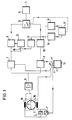
- a tube 4 is shown schematically, through which an electrically conductive medium flows. Electrodes 5 protrude into the tube 4 from opposite sides, each of which leads to an input of an input amplifier 6.
- the electrodes 5 detect potentials in the flowing medium which are different from one another when the medium is penetrated by a magnetic field generated by coils 3a, 3b.
- a DC generator 1 is provided to generate the DC magnetic field and a generator 2 is provided to generate an alternating magnetic field. Both generators 1, 2 are parallel to one another with the coils 3a and 3b in a circuit.
- the generators are controlled by a clock generator 15 in the clock A1 and B1 shown in FIGS. 2 and 3 for the two methods.
- the voltage U f reaches the inputs of two synchronous rectifiers 7 and 8.
- the synchronous rectifier 7 serves to rectify the voltage component u w corresponding to the alternating field.
- Synchronous rectifier 8 serves to rectify the component U g corresponding to the DC field. This too Rectifiers 7, 8 are controlled by the clock generator 15, specifically in the clock cycle A2 or B2 shown in FIG. 2 or 3.
- the synchronous rectifier 7 outputs the voltage components rectified by it to an evaluation circuit 9 for the alternating field.
- the synchronous rectifier 8 passes the voltage components rectified by it to an evaluation circuit 10 for the DC field.
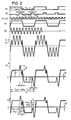
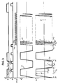
- the generators 1 and 2 generate a bipolar DC field 0 ⁇ 1 and an alternating field 0 ⁇ 2. These fields are superimposed on a field 0 ⁇ .
- the voltage U f has essentially the same profile as the field 0 ⁇ .
- the portion of the voltage corresponding to the DC field is evaluated in sections t g1 and t g2 . These sections are located at the ends of the half-periods T g / 2 of the constant field.
- the voltages are subtracted from one another in two successive sections t g1 and t g2 with the correct sign.
- You get (U p + u g ) tg1 - (U p - u g ) tg2 2u g
- the portions originating from the alternating field are added with the correct sign.
- the switch 13 is actuated as a function of the course of the voltage component 2u g in the manner described at the beginning.
- a detector 16 is provided which is responsive to changes of 2u g per unit of time, and, if these changes exceed a preset Audio measure per unit time, is operated via an OR gate 17 the switch. 13
- a detector 15 is provided for this purpose, which actuates the changeover switch 13 via the OR gate 17 when the voltage components 2u g exceed a predetermined level, for example due to interference.
- the changeover switch 13 is actuated in the same way as in the method according to claim 1.
Landscapes
- Physics & Mathematics (AREA)
- Electromagnetism (AREA)
- Fluid Mechanics (AREA)
- General Physics & Mathematics (AREA)
- Measuring Magnetic Variables (AREA)
- Measuring Volume Flow (AREA)
Applications Claiming Priority (2)
| Application Number | Priority Date | Filing Date | Title |
|---|---|---|---|
| DE19873728342 DE3728342A1 (de) | 1987-08-25 | 1987-08-25 | Verfahren zur erzeugung eines signals, das der stromstaerke eines fliessenden, elektrisch leitenden mediums entspricht, und schaltungsanordnungen zur durchfuehrung der verfahren |
| DE3728342 | 1987-08-25 |
Publications (3)
| Publication Number | Publication Date |
|---|---|
| EP0304774A2 true EP0304774A2 (fr) | 1989-03-01 |
| EP0304774A3 EP0304774A3 (fr) | 1992-01-15 |
| EP0304774B1 EP0304774B1 (fr) | 1994-06-29 |
Family
ID=6334447
Family Applications (1)
| Application Number | Title | Priority Date | Filing Date |
|---|---|---|---|
| EP88113286A Expired - Lifetime EP0304774B1 (fr) | 1987-08-25 | 1988-08-16 | Procédé pour produire un signal correspondant au débit d'un fluide conductible électriquement |
Country Status (2)
| Country | Link |
|---|---|
| EP (1) | EP0304774B1 (fr) |
| DE (2) | DE3728342A1 (fr) |
Cited By (5)
| Publication number | Priority date | Publication date | Assignee | Title |
|---|---|---|---|---|
| EP0521448A3 (en) * | 1991-07-04 | 1995-03-15 | Fischer & Porter Gmbh | Circuit for the determination of errors in a magnetic-inductive flowmeter arrangement |
| EP0416866B1 (fr) * | 1989-09-07 | 1996-05-01 | Kabushiki Kaisha Toshiba | Débitmètre électromagnétique utilisant des champs magnétiques de fréquences différentes |
| EP0730139A3 (fr) * | 1995-03-02 | 1997-02-26 | Yokogawa Electric Corp | Débitmètre électromagnétique |
| EP0791806A3 (fr) * | 1996-02-26 | 1998-02-04 | Aichi Tokei Denki Co., Ltd. | Débitmètre électromagnétique supprimant l'influence des variations de la tension de décalage |
| CN103591991A (zh) * | 2013-11-08 | 2014-02-19 | 上海大学 | 带有流体阻抗测量的电磁流量计 |
Family Cites Families (5)
| Publication number | Priority date | Publication date | Assignee | Title |
|---|---|---|---|---|
| US3991612A (en) * | 1975-10-14 | 1976-11-16 | Fischer & Porter Co. | Electromagnetic flowmeter usable in less-than full fluid lines |
| DE2557328C2 (de) * | 1975-12-19 | 1982-06-16 | Fischer & Porter GmbH, 3400 Göttingen | Induktiver Durchflußmesser mit getakteter Gleichstromerregung |
| DE2603694A1 (de) * | 1976-01-31 | 1977-08-04 | Rombach Johann Baptist | Elektronisches zaehlgeraet |
| DE2744845C3 (de) * | 1977-10-05 | 1985-08-08 | Flowtec AG, Reinach, Basel | Verfahren zur Kompensation der elektrochemischen Störgleichspannung bei der magnetisch-induktiven Durchflußmessung mit periodisch umgepoltem magnetischem Gleichfeld |
| FR2589571B1 (fr) * | 1985-10-31 | 1990-02-09 | Sereg Soc | Debitmetre electromagnetique a champ magnetique pulse |
-
1987
- 1987-08-25 DE DE19873728342 patent/DE3728342A1/de not_active Ceased
-
1988
- 1988-08-16 EP EP88113286A patent/EP0304774B1/fr not_active Expired - Lifetime
- 1988-08-16 DE DE3850462T patent/DE3850462D1/de not_active Expired - Lifetime
Cited By (6)
| Publication number | Priority date | Publication date | Assignee | Title |
|---|---|---|---|---|
| EP0416866B1 (fr) * | 1989-09-07 | 1996-05-01 | Kabushiki Kaisha Toshiba | Débitmètre électromagnétique utilisant des champs magnétiques de fréquences différentes |
| EP0521448A3 (en) * | 1991-07-04 | 1995-03-15 | Fischer & Porter Gmbh | Circuit for the determination of errors in a magnetic-inductive flowmeter arrangement |
| EP0730139A3 (fr) * | 1995-03-02 | 1997-02-26 | Yokogawa Electric Corp | Débitmètre électromagnétique |
| EP0791806A3 (fr) * | 1996-02-26 | 1998-02-04 | Aichi Tokei Denki Co., Ltd. | Débitmètre électromagnétique supprimant l'influence des variations de la tension de décalage |
| CN103591991A (zh) * | 2013-11-08 | 2014-02-19 | 上海大学 | 带有流体阻抗测量的电磁流量计 |
| CN103591991B (zh) * | 2013-11-08 | 2016-08-17 | 上海大学 | 带有流体阻抗测量的电磁流量计 |
Also Published As
| Publication number | Publication date |
|---|---|
| DE3728342A1 (de) | 1989-03-09 |
| EP0304774A3 (fr) | 1992-01-15 |
| EP0304774B1 (fr) | 1994-06-29 |
| DE3850462D1 (de) | 1994-08-04 |
Similar Documents
| Publication | Publication Date | Title |
|---|---|---|
| DE69532630T2 (de) | Magnetisch-induktiver Durchflussmesser | |
| DE3637794A1 (de) | Beruehrungsloses verfahren zum messen der dicke und der temperatur duenner sich bewegender metallbleche mittels foucaultstroemen | |
| DE102004057680A1 (de) | Verfahren zur Funktionsüberwachung eines Magnetisch Induktiven Durchflussmessaufnehmers | |
| CH694996A5 (de) | Verfahren zu Ueberpruefen eines elektromagnetischen Durchflussmessers und elektromagnetische Durchflussmesseranordnung. | |
| EP3559604B1 (fr) | Procédé permettant de faire fonctionner un débitmètre à induction magnétique et débitmètre à induction magnétique | |
| DE112013002522T5 (de) | Magnetelement-Steuervorrichtung, Verfahren zum Steuern einer magnetischen Vorrichtung und magnetische Detektionsvorrichtung | |
| DE3829564C2 (de) | Verfahren zur Erzeugung eines der Stromstärke eines fließenden, elektrisch leitenden Mediums entsprechenden Signals bei einem elektromagnetischen Durchflußmesser | |
| DE2634425A1 (de) | Verfahren und einrichtung zur messung der position einer magnetischen stange | |
| EP1584902B1 (fr) | Débitmètre électromagnétique et procédé de fontionnement d'un débitmètre électromagnétique | |
| EP0304774B1 (fr) | Procédé pour produire un signal correspondant au débit d'un fluide conductible électriquement | |
| DE2837113C2 (fr) | ||
| CH639200A5 (de) | Waermezaehler. | |
| DE3934901C2 (de) | Leitfähigkeitsdetektor | |
| DE102014216404B4 (de) | Strommessvorrichtung und Verfahren zum Erfassen eines Stroms | |
| EP0543053A1 (fr) | Circuit pour un dispositif de mesure du débit d'un fluide contenant des charges électriques | |
| DE2240054C3 (de) | Induktiver Strömungsmesser | |
| DE4221057C2 (de) | Verfahren zum Erfassen des Verbrauchs elektrischer Energie | |
| DE3148007C2 (fr) | ||
| DE3637801A1 (de) | Vorrichtung zur messung eines zeitlich konstanten oder sich aendernden magnetfeldes | |
| DE3625011C2 (fr) | ||
| DE60002706T2 (de) | Stromsensor | |
| DE69206157T2 (de) | Verfahren und vorrichtung zum erhalten kathodischen schutzes gegen korrosion. | |
| EP2923182A1 (fr) | Procédé pour faire fonctionner un débitmètre magnéto-inductif | |
| DE19843133A1 (de) | Verfahren zum Messen der Drehzahl einer Induktionsmaschine | |
| DE102017105959B4 (de) | Verfahren zum Betreiben eines magnetisch-induktiven Durchflussmessgeräts und ein magnetisch-induktives Durchflussmessgerät |
Legal Events
| Date | Code | Title | Description |
|---|---|---|---|
| PUAI | Public reference made under article 153(3) epc to a published international application that has entered the european phase |
Free format text: ORIGINAL CODE: 0009012 |
|
| AK | Designated contracting states |
Kind code of ref document: A2 Designated state(s): CH DE FR GB LI NL |
|
| PUAL | Search report despatched |
Free format text: ORIGINAL CODE: 0009013 |
|
| AK | Designated contracting states |
Kind code of ref document: A3 Designated state(s): CH DE FR GB LI NL |
|
| 17P | Request for examination filed |
Effective date: 19920519 |
|
| 17Q | First examination report despatched |
Effective date: 19920818 |
|
| GRAA | (expected) grant |
Free format text: ORIGINAL CODE: 0009210 |
|
| AK | Designated contracting states |
Kind code of ref document: B1 Designated state(s): CH DE FR GB LI NL |
|
| REF | Corresponds to: |
Ref document number: 3850462 Country of ref document: DE Date of ref document: 19940804 |
|
| ET | Fr: translation filed | ||
| GBT | Gb: translation of ep patent filed (gb section 77(6)(a)/1977) |
Effective date: 19941006 |
|
| PLBE | No opposition filed within time limit |
Free format text: ORIGINAL CODE: 0009261 |
|
| STAA | Information on the status of an ep patent application or granted ep patent |
Free format text: STATUS: NO OPPOSITION FILED WITHIN TIME LIMIT |
|
| 26N | No opposition filed | ||
| REG | Reference to a national code |
Ref country code: GB Ref legal event code: IF02 |
|
| PGFP | Annual fee paid to national office [announced via postgrant information from national office to epo] |
Ref country code: GB Payment date: 20050808 Year of fee payment: 18 |
|
| PGFP | Annual fee paid to national office [announced via postgrant information from national office to epo] |
Ref country code: NL Payment date: 20050812 Year of fee payment: 18 Ref country code: FR Payment date: 20050812 Year of fee payment: 18 |
|
| PGFP | Annual fee paid to national office [announced via postgrant information from national office to epo] |
Ref country code: CH Payment date: 20060815 Year of fee payment: 19 |
|
| PG25 | Lapsed in a contracting state [announced via postgrant information from national office to epo] |
Ref country code: NL Free format text: LAPSE BECAUSE OF NON-PAYMENT OF DUE FEES Effective date: 20070301 |
|
| GBPC | Gb: european patent ceased through non-payment of renewal fee |
Effective date: 20060816 |
|
| NLV4 | Nl: lapsed or anulled due to non-payment of the annual fee |
Effective date: 20070301 |
|
| REG | Reference to a national code |
Ref country code: FR Ref legal event code: ST Effective date: 20070430 |
|
| PGFP | Annual fee paid to national office [announced via postgrant information from national office to epo] |
Ref country code: DE Payment date: 20070822 Year of fee payment: 20 |
|
| REG | Reference to a national code |
Ref country code: CH Ref legal event code: PFA Owner name: FISCHER & PORTER GMBH Free format text: FISCHER & PORTER GMBH#DRANSFELDER STRASSE 2#GOETTINGEN (DE) -TRANSFER TO- FISCHER & PORTER GMBH#DRANSFELDER STRASSE 2#GOETTINGEN (DE) |
|
| PG25 | Lapsed in a contracting state [announced via postgrant information from national office to epo] |
Ref country code: GB Free format text: LAPSE BECAUSE OF NON-PAYMENT OF DUE FEES Effective date: 20060816 |
|
| REG | Reference to a national code |
Ref country code: CH Ref legal event code: PL |
|
| PG25 | Lapsed in a contracting state [announced via postgrant information from national office to epo] |
Ref country code: FR Free format text: LAPSE BECAUSE OF NON-PAYMENT OF DUE FEES Effective date: 20060831 Ref country code: LI Free format text: LAPSE BECAUSE OF NON-PAYMENT OF DUE FEES Effective date: 20070831 Ref country code: CH Free format text: LAPSE BECAUSE OF NON-PAYMENT OF DUE FEES Effective date: 20070831 |