EP0304820B1 - Panneau de commande avec affichage - Google Patents
Panneau de commande avec affichage Download PDFInfo
- Publication number
- EP0304820B1 EP0304820B1 EP88113517A EP88113517A EP0304820B1 EP 0304820 B1 EP0304820 B1 EP 0304820B1 EP 88113517 A EP88113517 A EP 88113517A EP 88113517 A EP88113517 A EP 88113517A EP 0304820 B1 EP0304820 B1 EP 0304820B1
- Authority
- EP
- European Patent Office
- Prior art keywords
- light
- liquid crystal
- crystal panel
- beams
- control system
- Prior art date
- Legal status (The legal status is an assumption and is not a legal conclusion. Google has not performed a legal analysis and makes no representation as to the accuracy of the status listed.)
- Expired - Lifetime
Links
Images


Classifications
-
- G—PHYSICS
- G06—COMPUTING OR CALCULATING; COUNTING
- G06F—ELECTRIC DIGITAL DATA PROCESSING
- G06F3/00—Input arrangements for transferring data to be processed into a form capable of being handled by the computer; Output arrangements for transferring data from processing unit to output unit, e.g. interface arrangements
- G06F3/01—Input arrangements or combined input and output arrangements for interaction between user and computer
- G06F3/03—Arrangements for converting the position or the displacement of a member into a coded form
- G06F3/041—Digitisers, e.g. for touch screens or touch pads, characterised by the transducing means
- G06F3/042—Digitisers, e.g. for touch screens or touch pads, characterised by the transducing means by opto-electronic means
- G06F3/0421—Digitisers, e.g. for touch screens or touch pads, characterised by the transducing means by opto-electronic means by interrupting or reflecting a light beam, e.g. optical touch-screen
-
- G—PHYSICS
- G06—COMPUTING OR CALCULATING; COUNTING
- G06F—ELECTRIC DIGITAL DATA PROCESSING
- G06F3/00—Input arrangements for transferring data to be processed into a form capable of being handled by the computer; Output arrangements for transferring data from processing unit to output unit, e.g. interface arrangements
- G06F3/01—Input arrangements or combined input and output arrangements for interaction between user and computer
- G06F3/02—Input arrangements using manually operated switches, e.g. using keyboards or dials
- G06F3/023—Arrangements for converting discrete items of information into a coded form, e.g. arrangements for interpreting keyboard generated codes as alphanumeric codes, operand codes or instruction codes
- G06F3/0238—Programmable keyboards
Definitions
- the invention of this application relates to an improved type of electronic control panel which is free of moving parts, and which is generally a multiple channel control system of great flexibility and versatility.
- touch panels of various kinds are known, for instance from US Patent No. 4 198 623 which discloses a display device in which light beams are shone from one side of the periphery of the screen in a plane substantially parallel to the screen surface towards light detectors located on the opposite edge of the screen periphery. An opaque object placed in the light path is detected if it blocks the path of a light beam travelling from a light source to the respective detector.
- touch panels for control systems may be of the capacitive, resistive, or radiant energy types.
- Radiant energy type touch panels typically use infrared radiation.
- the probe which must be used to activate the touch panel must be large for the radiant energy system, soft for the resistive system, and conductive for the capacitive system.
- any size of touch probe may be used as long as it is substantially opaque, and it does not need to be either soft of conductive.
- the system of this invention exhibits the capability for high resolution card reading, a significant advantage over other radiant systems where the resolution is low.
- the resistive and capacitive systems are basically without card reading capability.
- the device of this invention is of substantially low cost, and has good mechanical stability against vibration and the like.
- the control of this invention can mimic a momentary push button, a touch on/touch off switch, lighted switches, and push buttons. Also slide switches and rocker action switches may be simulated as well, without the use of moving parts.
- a control system actuable by an opaque member which comprises a liquid crystal panel; a light source; light detector means; and means for directing light through at least a portion of the liquid crystal panel to the light detector means.
- Control means are also provided for holding the liquid crystal panel portion through which the light passes in generally opaque condition, while preferably sequentially momentarily clarifying segments of the portion.
- momentary, sequential, transversely spaced light beams are generated between the light source and light detector means, being spaced and sequenced by the creation of the momentarily clarified segments, typically in differing, spaced portions of the liquid crystal panel.
- Timer and logic means are provided for correlating signals received from the light detector means with generated, individual, spaced light beams that create such signals. Accordingly, occlusion of at least one of the individual light beams with an opaque member causes a specific, characteristic response by the timer and logic means.
- the timer and logic means may be duly noted and processed by the timer and logic means, the identity of such light beams being recognized typically by their time of arrival at the light detector.
- the failure of the timer and logic means to receive the blocked light beam will also be recognized. This event will represent a non-standard condition, and will be duly processed by the timer and logic means as an instruction signal to activate a relay, send a signal to a microprocessor, to modify a display, or the like as dictated by the electronics of the system.
- a control system in which the control is achieved by blocking one or more of an array of typically parallel, laterally spaced light beams which are created in momentary sequential manner by the momentary clarification of spaced segments of a liquid crystal panel.
- the cycles of momentary creation of such transient, clear segments in the liquid crystal panel (LCD) may of course be many times per second so that the parallel light beams may be substantially equivalent to a continuous light beam.
- high frequency fluorescent radiation is used and sensed so that the control system may be used in ambient room light.
- the light source and light detector means used in the control of this invention may be positioned within a housing.
- the beams of light between the light source and the light detector means may leave the housing, and may reenter the housing again, to pass across an external, exposed area. This permits selective occlusion of the beams by an opaque member such as the finger in the external, exposed area.
- mechanical instruments may be used to occlude the light beams, if desired.
- the timer and logic means may cause a display of indicia on a liquid crystal display panel, which panel may be the same as or different from the liquid crystal panel discussed above.
- This indicia display may correlate with the light beams to provide a visual display.
- an LCD display panel positioned behind the light beams may be connected to a microprocessor or other software as part of the timer and logic means to display what each light beam path represents or controls. Since the LCD display behind the light beams is electronically created, after one or more light beam paths have been selected by blocking the passage of light in the path, the microprocessor driven LCD display may change to provide a second matrix of selections. After this selection a third matrix of selections may be provided, and so on without limitation, so that an exceedingly complex series of functions may be controlled from a single control unit in accordance with this invention, limited only by the nature of the software used in the control process.
- both the light source and the light detector means may be monolithic, i.e., they both may be simply single units that respectively emit and receive light signals of all of the spaced light beams.
- identification of the individual light beams may be determined in the timer and logic means by the time of arrival of the light beam at the light detector means.
- multiple light sources may be used and multiple light detector means, being gated as before through the liquid crystal display panel in a manner controlled by the timer and control means.
- a second liquid crystal panel may be provided and positioned whereby the same light can pass through clarified portions of both liquid crystal panels.
- the control means may also hold the second liquid crystal panel in generally opaque condition while sequentially momentarily clarifying segments of the second panel. As a result of this, individual, spaced light beams pass through clarified portions of both said panels, for less spreading of the beams at the light detector means. This provides greater precision of the control system of this invention, permitting smaller opaque objects to be used for proper control, permitting larger spaces into which the finger or other opaque object may be inserted, and the like.
- a space is provided between the liquid crystal panels for insertion of a finger or other opaque member to occlude at least one of the individual light beams.
- an added liquid crystal panel may be positioned to intersect added beams of light which travel in a different direction from and intersect the previously described space light beams.
- These added liquid crystal panels are different from, but may be used in the same apparatus as, the second liquid crystal panel described above.
- Means for producing the added beams of light on one side of the added liquid crystal panel may be provided.
- Means for detecting the added light beams on the other side of the added liquid crystal panel are also present. These means for producing added beams of light and detecting them may constitute a separate light source and detector, or by a suitable arrangement of mirrors and electronic timing the same light source and detector as previously described may be used for both functions.
- the control means is capable of holding at least a portion of the added liquid crystal panel in generally opaque condition while sequentially momentarily clarifying segments of the added liquid crystal panel portion in a manner that correlates with the pattern of momentarily clarified segments of the added liquid crystal panel portion in a manner that correlates with the pattern of momentarily clarified segments of the other liquid crystal panel portion.
- the means for detecting the added light beams is in electronic communication with the timer and logic means.
- such a control system is capable of detecting the position of one or more opaque objects such as a finger on a two dimensional grid across which the light beams described above intersect.
- control system of this invention can be used to display a large, two dimensional grid with many potential finger positions, for example a matrix of 100 positions in 10 rows of 10 positions each.
- the matrix may be displayed to the user by a liquid crystal display panel, which is driven by the software of the system. If the user touches the displayed position number 64 out of 100 positions, a characteristic electronic response can be provided which is completely different from the electronic response that would be provided if the user were to touch position number 3.
- the liquid crystal display panel which backs the two dimensional field may change to an entirely different display, providing the user with further decisions, or communicating information to him, or any other response desired.
- liquid crystal display panel is used in some places above, it is to be understood that the liquid crystal panels used in this invention do not necessarily display anything, but rather are used as gates for light in the manner described above.
- liquid crystal display panel is not intended to absolutely mandate the existence of a display function to liquid crystal panels used in this invention, although the presence of a display function on part of a liquid crystal display panel, along with a gating function on another part of the same panel, is a desirable feature in many embodiments.
- control system 10 including a housing 12 that may be mounted on a vehicle dashboard or the panel of an appliance or any other device.
- Housing 12 defines a depressed wall area 14 which is typically made of transparent material, as is often the entire front wall 16 of housing 12.
- Rear housing portion 18 is provided to enclose the components of control system 10.
- Light source 20 may be a simple, elongated fluorescent light bulb shown in cross-section in Fig. 2, and extending substantially the entire width of housing 12.
- Liquid crystal display panel 22 may be of conventional design, being positioned behind transparent recessed wall 14 as shown in Fig. 2 and also blocking the forward paths of light from light source 20. Accordingly, liquid crystal display panel 22 can form one or more transparent window sections 24 in that portion of panel 22 which can otherwise block light from traveling forward from light source 20. Such light passes through windows 24 of liquid crystal display panel 22 forwardly, to be reflected 90 degrees by mirror portion 26. The light then passes through transparent wall portion 28 of housing 12, normally passing through angled transparent wall 28 into the recess adjacent wall 14.
- light beam 30 passes through transparent, angled wall 32 of housing 12 to be reflected again by 90 degrees off of angled mirror 34, to pass into light detector means 36, which may be a photovoltaic cell, a phototransistor, a light dependent resistor, or any other conventional light receptor.
- An array of LCD control wires 38 permit window portions 24 of liquid crystal display panel (LCD) 22 to be selectively clarified or rendered opaque to gate the light from source 20. As shown in Fig. 1, a series of separate, sequentially spaced in both time and space, light beams 30 may thus pass through the depressed space along wall 14 in a manner which is controlled by the respective window portions 24 of LCD 22, as specifically controlled by LCD wires 38.
- LCD liquid crystal display panel
- the timer and logic means of control system 10 includes a microprocessor board 40 which is in electrical connection with light detector 36, LCD control wires 38, and LCD display wires 42 (some being deleted for clarity). Wires 42 are connected in a two dimensional matrix across LCD 22 for controlling visual displays of the LCD in a manner controlled by microprocessor 40.
- a series of rectangular areas 48 have been defined by liquid crystal display 22, as controlled by microprocessor board 40 and LCD display wires 42.
- the timer and logic means identifies the particular light beam, gated by a particularly positioned and timed transient window 24 in LCD 22.
- Each light beam 30 is identified by its time of arrival, or failure to arrive, at detector 36.
- one of the areas 48, particularly 48a is fully highlighted to indicate occlusion of the light beam and selection of that area.
- a characteristic electronic signal may be sent out of the control system to accomplish its predetermined purpose such as starting a motor, actuating a computer function of the like.
- the light beams 30 may be gated to be 1 millisecond, sequential pulses, for example, so that a repeating cycle of light beam generation may take place many times per second.
- the timer and logic means reflects that condition, and the specific characteristic signals which their occlusion would initiate do not take place.
- Relays 51 may be present, being controlled by the system for desired responses upon actuation.
- Fig. 4 is a purely schematic diagram, illustrating a portion of the functioning of the embodiment of Figs. 1 through 3. It can be seen that elongated light source 20 illuminates light in many directions, some of which pass through a specific, momentarily clarified window 24 in LCD 22 to impinge upon photodetector 36. It can be seen that the presence of finger 49 occludes these light beams to at least reduce the amount of light getting to the photodetector. If the finger is close to window 24, the light can become completely occluded, but, at least, a characteristic reduction of light to the photodetector can be achieved to cause the desired actuation, in conjunction with the proper timing as sensed by the timer and logic means.
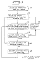
- Fig. 3 shows a flow chart of functions that may be built into the timer and logic means for operation of the device of Figs. 1 through 4.
- the initial step 50 is basically to turn on the system and prepare it to function.
- the next step 52 positions a count register to position number 1.
- the next step 54 causes all LCD windows 24 to become opaque except for the window which corresponds to the particular count register number, each of the clarifiable windows 24 being assigned a count register number. In the double-gated system to be described below, two windows are kept open, but otherwise the same flow chart may be used.
- step 56 is to sample the signal level from photodetector 36. If the signal level is below a characteristic value, a signal is emitted 58 to the control circuit to cause the system to cycle back to step 52.
- the system determines (60) if the count register is at a maximum number corresponding to the last LCD window 24 to be opened. If so, the system recycles again to step 52. If not, the count register is advanced (62) by one position, and the system recycles to step 54.
- Fig. 6 a more complex use of the system of Figs. 1 through 4 is disclosed.
- Control system 10 is shown, with the respective plurality of sequential light beams 30 being shown, passing across LCD 22 as illustrated in Figs. 1 and 2.
- Optical card 64 is provided, being positioned in a predetermined manner to intersect light beams 30.
- Optical card 64 is opaque, having a series of transparent portions 66 through which light beams 30 can pass.
- optical card 64 selectively occludes some of the light beams 30, and allows others of them to pass.
- complex information can be quickly transmitted from the card though the control system of this invention to a computer or other device. For example, complex data for a computer operated milling machine might be transferred in this manner, or programming information, or any other desired information.
- a complex pattern of information can be created using a single, constant light source 20 and a single receptor 36.
- Each individual light beam 30 is identified by its time of arrival at receptor 36, while its failure to arrive is used as positive signal.
- Fig. 5 a modification of the embodiment of Figs. 1 through 4 is disclosed. Apart from the modifications shown, the system may be constructed and may operate in the manner of the previous embodiment.
- Light source 20a is provided, and may be identical to the previous light source 20.
- Photodetector 36a may be similar in structure and function to the previous photodetector 36, and LCD 22a may also be substantially identical in structure and function to the previous LCD 22.
- a second liquid crystal panel 68 may be provided, which may or may not have a display function, but does have a gating function. It, as well as LCD 22a is connected to the timer and logic means to produce an intermittant sequential, transient array of momentarily clarified segments of the normally opaque liquid crystal panel 68.
- windows 70 may be sequentially created in the same order and corresponding position to windows 24a of liquid crystal panel 22a, which in turn are similar in function to windows 24 of the previous embodiment.
- this embodiment may also be similar in structure and function to the previous embodiments except as otherwise disclosed.
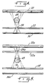
- a light source 20b, photodetector 36b, liquid crystal display 22b and second liquid crystal display 68b may function in the manner described with respect to the previous embodiment.
- a second system is provided, being positioned at an angle to the first system 20b, 22b, 68b, 36b. Specifically, the angle is shown to be substantially 90 degrees to the first system, but other angles may be used as desired.
- the second system comprises a light source 20c, a pair of liquid crystal panels 22c, 68c, and a photodetector 36c, each of which may be of a structure and function which is substantially identical to the analogous parts of identical number in the previous embodiments.
- the embodiment of Fig. 8 is a double detection system in which gated intersecting beams of light are separately detected.
- the transient, sequential clarified windows 24b, 24c, 70b 70c which are formed are correlated in the sequence and pattern of their formation.
- windows 24b, 70b may be formed, and remain open and transmitting light while each of the series of windows 24c, 70c are transiently and sequentially formed and extinguished, as controlled by the timer and control means, then, the next, adjacent windows 24b, 70b are created and the former windows are extinguished, and, once again, the entire series of windows 24c, 70c are transiently and sequentially formed and extinguished.
- the pattern of positive responses to light indicated by photodetectors 36b and 36c may be integrated together and, from that, the coordinates of the finger 49 or other opaque object in the two dimensional field defined between liquid crystal panels 22b, 22c, 68b, 68c may be calculated.
- This information may be used to make a characteristic electronic response to the placement of finger 49 at various positions in the two dimensional area, to effectively provide a two dimensional matrix of electronic selections which may be made.
- a liquid crystal display panel 80 may back up the two dimensional area to provide desired indicia as a guide to show where the finger should be placed for the desired selection or choice, and to also provide visual responses back to the user. With proper mirroring LCD display panel 80 may carry all windows 24b, 24c, 70b, 70c.
- Fig. 7 shows a modification of the embodiment of Figs. 1 through 4, in which liquid crystal panel 22d is modified to occlude the light beam 30 adjacent receptor 36d rather than the light source.
- windows 24d may be created and extinguished adjacent receptor 36d in a manner and for purposes as described above while providing improved precision of light gating and sensing.
- the structure and function of all parts may be as described above.
- a control system is provided by this invention for an electronic control panel or the like in virtually any desired field, which panel is free of moving parts, and which has low cost of manufacture, and great flexibility and versatility.
Landscapes
- Engineering & Computer Science (AREA)
- General Engineering & Computer Science (AREA)
- Theoretical Computer Science (AREA)
- Human Computer Interaction (AREA)
- Physics & Mathematics (AREA)
- General Physics & Mathematics (AREA)
- Liquid Crystal (AREA)
- Devices For Indicating Variable Information By Combining Individual Elements (AREA)
- Electrochromic Elements, Electrophoresis, Or Variable Reflection Or Absorption Elements (AREA)
- Liquid Crystal Display Device Control (AREA)
Claims (21)
- Système de commande (10) pouvant être activé par un organe opaque, qui comprend :
un écran à cristaux liquides (22); une source de lumière (20); des moyens à détecteur de lumière (36); des moyens (26,34,38) pour envoyer de la lumière à travers au moins une portion dudit écran d'affichage à cristaux liquides vers lesdits moyens à détecteur de lumière; et des moyens de commande (40) pour former de façon transitoire au moins une fenêtre transparente (24) dans ledit écran à cristaux liquides (22), à une position permettant à ladite lumière de passer à partir de ladite source de lumière (20) à travers ledit écran (22) et vers lesdits moyens à détecteur de lumière (36), de sorte qu'au moins un faisceau lumineux (30) peut être formé de façon transitoire, pouvant subir une occlusion par ledit organe opaque pour provoquer une réponse caractéristique à partir dudit système de commande (10). - Système de commande selon la revendication 1, dans lequel lesdits moyens de commande sont capables de former de façon transitoire des fenêtres transparentes (24) dans ledit écran (22), ayant des positions différentes sur ledit écran (22), pour permettre le passage de portions espacées dudit faisceau lumineux (30).
- Système de commande (10) pouvant être activé par un organe opaque, qui comprend :
un écran à cristaux liquides (22); une source de lumière (20); des moyens à détecteur de lumière (36); des moyens (26,34,38) pour envoyer de la lumière à travers au moins une portion dudit écran à cristaux liquides (22) vers lesdits moyens à détecteur de lumière (36); des moyens de commande (40) pour maintenir ladite portion dudit écran à cristaux liquides dans un état opaque d'une manière générale tout en éclaircissant séquentiellement et momentanément des segments de ladite portion, de sorte que des faisceaux lumineux momentanés, séquentiels, espacés transversalement (30) sont générés entre ladite source de lumière (20) et lesdits moyens à détecteur de lumière (36); et des moyens logiques et de synchronisation pour mettre en corrélation les signaux reçus à partir desdits moyens à détecteur de lumière (36) avec lesdits faisceaux lumineux générés individuels, espacés transversalement (30) qui créent lesdits signaux, de sorte que l'occlusion d'au moins un desdits faisceaux lumineux individuels avec ledit organe opaque cause une réponse spécifique, caractéristique, par lesdits moyens logiques et de synchronisation. - Système de commande selon la revendication 3, dans lequel ladite source de lumière (20) et lesdits moyens à détecteur de lumière (36) sont positionnés à l'intérieur d'un boîtier (12), les faisceaux lumineux (30) entre ladite source de lumière (20) et lesdits moyens à détecteur de lumière (36) quittant ledit boîtier (12) et étant réintroduits dans ledit boîtier (12) de nouveau pour passer à travers une zone externe, exposée, pour permettre l'occlusion sélective desdits faisceaux (30) par un organe opaque dans ladite zone externe exposée.
- Système de commande selon la revendication 3, dans lequel lesdits moyens logiques et de synchronisation causent l'affichage d'indices sur une section de l'écran à cristaux liquides qui est en corrélation avec les faisceaux lumineux (30) pour fournir un système de commande à affichage visuel.
- Système de commande selon la revendication 5, dans lequel le même écran à cristaux liquides (22) sert à afficher lesdits indices et à éclaircir séquentiellement et momentanément lesdits segments (24).
- Système de commande selon la revendication 3, dans lequel lesdits moyens à détecteur de lumière (36) sont monolithiques.
- Système de commande selon la revendication 3, dans lequel ladite source de lumière (20) est monolithique.
- Système de commande selon la revendication 3, dans lequel un second écran à cristaux liquides (68) est prévu et positionné de telle sorte que la même lumière peut passer à travers des portions éclaircies (24a,70) des deux écrans à cristaux liquides (22a,68), lesdits moyens de commande (40) maintenant aussi ledit second écran à cristaux liquides (68) dans un état opaque d'une manière générale tout en éclaircissant séquentiellement et momentanément des segments (70) dudit second écran, de sorte que lesdits faisceaux lumineux individuels espacés transversalement (30) passent à travers des portions éclaircies desdits deux écrans pour une dispersion moindre desdits faisceaux au niveau desdits moyens à détecteur de lumière (36).
- Système de commande selon la revendication 9, dans lequel un espace est prévu entre lesdits écrans à cristaux liquides (68,22a) pour que l'insertion d'un organe opaque (49) entraîne l'occlusion d'au moins l'un de chacun desdits faisceaux lumineux individuels concourants.
- Système de commande selon la revendication 3, dans lequel un écran à cristaux liquides additionnel (22b) est positionné de manière à couper des faisceaux lumineux additionnels qui vont dans une direction différente desdits faisceaux lumineux espacés et les coupent; comprenant des moyens (20b) pour produire lesdits faisceaux lumineux additionnels d'un côté dudit écran à cristaux liquides additionnel (22b); des moyens (36b) pour détecter lesdits faisceaux lumineux additionnels de l'autre côté de l'écran à cristaux liquides additionnel (22b); lesdits moyens de commande (40) étant aussi capables de maintenir au moins une portion dudit écran à cristaux liquides additionnel (22b) dans un état opaque d'une manière générale tout en éclaircissant séquentiellement et momentanément des segments (24b) de ladite portion dudit écran à cristaux liquides additionnel d'une manière qui est en corrélation avec le motif des segments momentanément éclaircis (24b) de la portion (24c) de l'autre écran à cristaux liquides, lesdits moyens (36b) pour détecter lesdits faisceaux lumineux additionnels étant en communication électronique avec lesdits moyens logiques et de synchronisation, de sorte que la position d'au moins un objet opaque (49) qui entraîne l'occlusion desdits faisceaux lumineux concourants peut être située par ledit système de commande dans un domaine bidimensionnel et diverses réponses électroniques peuvent être initiées en fonction de ladite position.
- Système de commande selon la revendication 4, dans lequel lesdits moyens logiques et de synchronisation causent l'affichage d'indices sur une section de l'écran à cristaux liquides qui est en corrélation avec les faisceaux lumineux pour fournir un système de commande à affichage visuel.
- Système de commande selon la revendication 12, dans lequel un second écran à cristaux liquides (68) est prévu et positionné de telle sorte que la même lumière peut passer à travers des portions éclaircies des deux écrans à cristaux liquides (68,22a), lesdits moyens de commande (40) maintenant aussi ledit second écran à cristaux liquides (68) dans un état opaque d'une manière générale tout en éclaircissant séquentiellement et momentanément des segments (70) dudit second écran (68), de sorte que lesdits faisceaux lumineux individuels espacés (30) passent à travers des portions éclaircies desdits deux écrans (68,22a) pour une dispersion moindre desdits faisceaux au niveau desdits moyens à détecteur de lumière.
- Système de commande selon la revendication 12, dans lequel un écran à cristaux liquides additionnel (22b) est positionné de manière à couper des faisceaux lumineux additionnels qui vont dans une direction différente desdits faisceaux lumineux espacés et les coupent; comprenant des moyens (20b) pour produire lesdits faisceaux lumineux additionnels d'un côté dudit écran à cristaux liquides additionnel (22b); des moyens (36b) pour détecter lesdits faisceaux lumineux additionnels de l'autre côté de l'écran à cristaux liquides additionnel (22b); lesdits moyens de commande (40) étant aussi capables de maintenir au moins une portion dudit écran à cristaux liquides additionnel (22b) dans un état opaque d'une manière générale tout en éclaircissant séquentiellement et momentanément des segments (24b) de ladite portion dudit écran à cristaux liquides additionnel d'une manière qui est en corrélation avec le motif des segments momentanément éclaircis (24b) de la portion (24c) de l'autre écran à cristaux liquides, lesdits moyens (36b) pour détecter lesdits faisceaux lumineux additionnels étant en communication électronique avec lesdits moyens logiques et de synchronisation, de sorte que la position d'au moins un objet opaque (49) qui entraîne l'occlusion desdits faisceaux lumineux concourants peut être située par ledit système de commande dans un domaine bidimensionnel et diverses réponses électroniques peuvent être initiées en fonction de ladite position.
- Système de commande selon la revendication 14, dans lequel lesdits moyens à détecteur de lumière (36b) et ladite source de lumière (20b) sont monolithiques.
- Système de commande selon la revendication 14, dans lequel au moins un écran à cristaux liquides sert à afficher des indices et aussi à éclaircir séquentiellement lesdits segments.
- Système de commande selon la revendication 14, dans lequel un espace est prévu entre lesdits écrans à cristaux liquides (22b,68b,22c,68c) pour que l'insertion d'un organe opaque (49) entraîne l'occlusion d'au moins l'un de chacun desdits faisceaux lumineux individuels concourants.
- Système de commande selon la revendication 3, dans lequel un second écran à cristaux liquides (68c) est prévu et positionné de telle sorte que la même lumière peut passer à travers des portions éclaircies (24c,70c) des deux écrans à cristaux liquides (22c,68c), lesdits moyens de commande (40) maintenant aussi ledit second écran à cristaux liquides (68c) dans un état opaque d'une manière générale tout en éclaircissant séquentiellement et momentanément des segments (70c) dudit second écran (68c), de sorte que lesdits faisceaux lumineux individuels espacés (30) passent à travers des portions éclaircies (24c,70c) desdits deux écrans pour une dispersion moindre desdits faisceaux au niveau desdits moyens à détecteur de lumière (36c), et l'occlusion d'au moins un desdits faisceaux lumineux individuels avec un organe opaque (49) cause une réponse spécifique, caractéristique, par lesdits moyens logiques et de synchronisation; et dans lequel des écrans à cristaux liquides additionnels (68b,22b) supplémentaires sont positionnés de manière à couper des faisceaux lumineux additionnels qui vont dans une direction différente desdits faisceaux lumineux espacés (30) et les coupent ; comprenant des moyens (20b) pour produire lesdits faisceaux lumineux additionnels d'un côté desdits écrans à cristaux liquides additionnels; des moyens (36b) pour détecter lesdits faisceaux lumineux additionnels de l'autre côté des écrans à cristaux liquides additionnels; lesdits moyens de commande (40) étant aussi capables de maintenir au moins une portion desdits écrans à cristaux liquides additionnels (68b,22b) dans un état opaque d'une manière générale tout en éclaircissant séquentiellement et momentanément des segments (70b,24b) de ladite portion desdits écrans à cristaux liquides additionnels d'une manière qui est en corrélation avec le motif de segments momentanément éclaircis de la portion (24c) de l'autre écran à cristaux liquides, lesdits moyens (36b) pour détecter lesdits faisceaux lumineux additionnels étant en communication électronique avec lesdits moyens logiques et de synchronisation, de sorte que la position d'au moins un objet opaque qui entraîne l'occlusion desdits faisceaux lumineux concourants peut être située par ledit système de commande dans un domaine bidimensionnel et diverses réponses électroniques peuvent être initiées en fonction de ladite position.
- Système de commande selon la revendication 18, dans lequel un espace est prévu entre lesdits écrans à cristaux liquides (22b,22c,68b,68c) pour que l'insertion d'un organe opaque entraîne l'occlusion d'au moins l'un de chacun desdits faisceaux lumineux individuels concourants.
- Procédé d'activation d'un système de commande avec un organe opaque, comprenant les étapes de production d'une série de faisceaux lumineux, séquentiels, espacés transversalement (30) par la transmission de lumière à travers un écran à cristaux liquides (22), et d'éclaircissement séquentiel et momentané de segments espacés (24) d'au moins une portion dudit écran à cristaux liquides tout en maintenant des portions adjacentes dudit écran dans un état opaque d'une manière générale; et par la suite de détection desdits faisceaux lumineux momentanés, séquentiels, espacés transversalement avec des moyens à détecteur de lumière (36), de corrélation des signaux reçus à partir desdits moyens à détecteur de lumière (36) avec lesdits faisceaux lumineux espacés transversalement (30) qui créent lesdits signaux par des moyens logiques et de synchronisation; ledit procédé incluant en outre l'étape d'occlusion d'au moins un desdits faisceaux lumineux individuels avec un organe opaque (49) pour causer une réponse spécifique, caractéristique, par lesdits moyens logiques et de synchronisation.
- Procédé selon la revendication 20, dans lequel les segments éclaircis séquentiellement et momentanément (24) dudit écran à cristaux liquides (22) se succèdent rapidement dans un cycle avec une fréquence de plus d'un cycle par seconde.
Priority Applications (1)
| Application Number | Priority Date | Filing Date | Title |
|---|---|---|---|
| AT88113517T ATE102720T1 (de) | 1987-08-25 | 1988-08-19 | Steuertafel mit anzeige. |
Applications Claiming Priority (2)
| Application Number | Priority Date | Filing Date | Title |
|---|---|---|---|
| US07/089,138 US4847606A (en) | 1987-08-25 | 1987-08-25 | Control and display system |
| US89138 | 1987-08-25 |
Publications (3)
| Publication Number | Publication Date |
|---|---|
| EP0304820A2 EP0304820A2 (fr) | 1989-03-01 |
| EP0304820A3 EP0304820A3 (en) | 1990-05-30 |
| EP0304820B1 true EP0304820B1 (fr) | 1994-03-09 |
Family
ID=22215896
Family Applications (1)
| Application Number | Title | Priority Date | Filing Date |
|---|---|---|---|
| EP88113517A Expired - Lifetime EP0304820B1 (fr) | 1987-08-25 | 1988-08-19 | Panneau de commande avec affichage |
Country Status (6)
| Country | Link |
|---|---|
| US (1) | US4847606A (fr) |
| EP (1) | EP0304820B1 (fr) |
| JP (1) | JPH01103722A (fr) |
| AT (1) | ATE102720T1 (fr) |
| CA (1) | CA1310773C (fr) |
| DE (1) | DE3888262T2 (fr) |
Families Citing this family (53)
| Publication number | Priority date | Publication date | Assignee | Title |
|---|---|---|---|---|
| US4990901A (en) * | 1987-08-25 | 1991-02-05 | Technomarket, Inc. | Liquid crystal display touch screen having electronics on one side |
| US4951035A (en) * | 1987-08-25 | 1990-08-21 | Technomarket, Inc. | Liquid crystal display touch screen with cross-aligned scanning |
| AT394279B (de) * | 1990-03-14 | 1992-02-25 | Vaillant Gmbh | Elektronische schaltuhr |
| USD339230S (en) | 1991-05-16 | 1993-09-14 | Thompson James E | Solar powered key chain display |
| US5196836A (en) * | 1991-06-28 | 1993-03-23 | International Business Machines Corporation | Touch panel display |
| CA2065990A1 (fr) * | 1991-06-28 | 1992-12-29 | International Business Machines Corporation | Panneau d'affichage tactile |
| US5579035A (en) * | 1991-07-05 | 1996-11-26 | Technomarket, L.P. | Liquid crystal display module |
| GB2268263A (en) * | 1992-06-30 | 1994-01-05 | Ibm | Input device for a visual display unit |
| EP0601651A1 (fr) * | 1992-12-10 | 1994-06-15 | Koninklijke Philips Electronics N.V. | Tablette optique sensible au toucher à l'aide d'intersection de secteurs |
| US5381388A (en) * | 1993-07-28 | 1995-01-10 | Technomarket, L.P. | Digital clock |
| EP0918241A3 (fr) * | 1993-11-28 | 1999-06-23 | Smartlight Limited | Dispositif d'observation d'image transparente |
| US5729250A (en) * | 1995-05-08 | 1998-03-17 | International Business Machines Corporation | Front cover assembly for a touch sensitive device |
| US5635724A (en) * | 1995-06-07 | 1997-06-03 | Intecolor | Method and apparatus for detecting the location of an object on a surface |
| US5812102A (en) * | 1997-03-12 | 1998-09-22 | Union Switch & Signal Inc. | Vital monitoring system for seven-segment display used in railroad applications |
| DE19856007A1 (de) * | 1998-12-04 | 2000-06-21 | Bayer Ag | Anzeigevorrichtung mit Berührungssensor |
| US6097302A (en) * | 1999-06-23 | 2000-08-01 | Union Switch & Signal, Inc. | System and method for monitoring a plural segment light-emitting display |
| JP4538933B2 (ja) * | 2000-10-06 | 2010-09-08 | 三菱電機株式会社 | 位置検出機能つき液晶表示装置 |
| US9213443B2 (en) * | 2009-02-15 | 2015-12-15 | Neonode Inc. | Optical touch screen systems using reflected light |
| SE0103835L (sv) * | 2001-11-02 | 2003-05-03 | Neonode Ab | Pekskärm realiserad av displayenhet med ljussändande och ljusmottagande enheter |
| US9052777B2 (en) | 2001-11-02 | 2015-06-09 | Neonode Inc. | Optical elements with alternating reflective lens facets |
| US9778794B2 (en) | 2001-11-02 | 2017-10-03 | Neonode Inc. | Light-based touch screen |
| US8095879B2 (en) | 2002-12-10 | 2012-01-10 | Neonode Inc. | User interface for mobile handheld computer unit |
| US8674966B2 (en) | 2001-11-02 | 2014-03-18 | Neonode Inc. | ASIC controller for light-based touch screen |
| US9164654B2 (en) * | 2002-12-10 | 2015-10-20 | Neonode Inc. | User interface for mobile computer unit |
| US9052771B2 (en) * | 2002-11-04 | 2015-06-09 | Neonode Inc. | Touch screen calibration and update methods |
| US20100238139A1 (en) * | 2009-02-15 | 2010-09-23 | Neonode Inc. | Optical touch screen systems using wide light beams |
| US8339379B2 (en) * | 2004-04-29 | 2012-12-25 | Neonode Inc. | Light-based touch screen |
| US8416217B1 (en) | 2002-11-04 | 2013-04-09 | Neonode Inc. | Light-based finger gesture user interface |
| US9389730B2 (en) * | 2002-12-10 | 2016-07-12 | Neonode Inc. | Light-based touch screen using elongated light guides |
| US20050247863A1 (en) * | 2004-05-04 | 2005-11-10 | Susanne Arens | Photoelectric switch for use in sealed cases |
| WO2006060875A1 (fr) * | 2004-12-09 | 2006-06-15 | Rpo Pty Limited | Dispositifs de distribution de puissance optique |
| US8471830B2 (en) * | 2007-07-06 | 2013-06-25 | Neonode Inc. | Scanning of a touch screen |
| EP2068212A1 (fr) * | 2007-12-06 | 2009-06-10 | The Swatch Group Research and Development Ltd. | Objet portable tel qu'une pièce d'horlogerie comprenant des moyens d'enclenchement d'une fonction de commande électronique |
| TWI406045B (zh) * | 2008-06-30 | 2013-08-21 | Ibm | 具有smt元件作為光閘之光學接觸面板及在該面板上之形成光閘的方法 |
| KR101554606B1 (ko) | 2008-08-07 | 2015-10-06 | 랩트 아이피 리미티드 | 변조된 에미터를 가진 광학 제어 시스템 |
| US8426799B2 (en) * | 2008-08-07 | 2013-04-23 | Rapt Ip Limited | Optical control system with feedback control |
| US9092092B2 (en) | 2008-08-07 | 2015-07-28 | Rapt Ip Limited | Detecting multitouch events in an optical touch-sensitive device using touch event templates |
| US8350831B2 (en) | 2008-08-07 | 2013-01-08 | Rapt Ip Limited | Method and apparatus for detecting a multitouch event in an optical touch-sensitive device |
| DE112008003983T5 (de) * | 2008-09-15 | 2011-07-21 | Hewlett-Packard Development Co., L.P., Tex. | Berührungsbildschirmanzeige mit mehreren Kameras |
| US20100198026A1 (en) * | 2009-02-02 | 2010-08-05 | Tpo Displays Corp. | Portable measuring apparatus and measuring method for detecting sunburn |
| US8976158B2 (en) | 2009-02-15 | 2015-03-10 | Neonode Inc. | User interface for white goods and associated multi-channel proximity sensors |
| US8775023B2 (en) | 2009-02-15 | 2014-07-08 | Neanode Inc. | Light-based touch controls on a steering wheel and dashboard |
| TWI420371B (zh) * | 2009-06-23 | 2013-12-21 | Raydium Semiconductor Corportation | 光學式觸控系統及其運作方法 |
| ITTN20090012A1 (it) * | 2009-09-25 | 2011-03-25 | Daniele Bernardini | Griglia optoelettronica per monitor industriali e commerciali con funzionalita' "multitouch screen" |
| TWI497376B (zh) | 2011-07-22 | 2015-08-21 | 拉普特Ip有限公司 | 在光學觸敏裝置中使用之光學耦合器總成 |
| US9524060B2 (en) | 2012-07-13 | 2016-12-20 | Rapt Ip Limited | Low power operation of an optical touch-sensitive device for detecting multitouch events |
| US9092093B2 (en) | 2012-11-27 | 2015-07-28 | Neonode Inc. | Steering wheel user interface |
| US12032817B2 (en) | 2012-11-27 | 2024-07-09 | Neonode Inc. | Vehicle user interface |
| US9664555B2 (en) * | 2012-12-18 | 2017-05-30 | Apple Inc. | Electronic devices with light sensors |
| GB2607548A (en) | 2018-05-18 | 2022-12-07 | 1004335 Ontario Inc Carrying On Business As A D Metro | Optical touch sensor devices and systems |
| WO2020112585A1 (fr) | 2018-11-28 | 2020-06-04 | Neonode Inc. | Capteur d'interface utilisateur d'automobiliste |
| GB2594585B (en) | 2020-04-03 | 2022-07-20 | 1004335 Ontario Inc Carrying On Business As A D Metro | Optical touch sensor systems and optical detectors with noise mitigation |
| CN116420125A (zh) | 2020-09-30 | 2023-07-11 | 内奥诺德公司 | 光学触摸传感器 |
Family Cites Families (23)
| Publication number | Priority date | Publication date | Assignee | Title |
|---|---|---|---|---|
| US3056030A (en) * | 1960-08-31 | 1962-09-25 | Burroughs Corp | Light responsive photo-optical keyboard |
| DE1463275B1 (de) * | 1963-09-04 | 1970-07-23 | Holzer Patent Ag | Vorrichtung zur Programmvorwahl bei Waschmaschinen |
| US3398290A (en) * | 1965-04-02 | 1968-08-20 | Carl J. Basehore | Photoelectric wall switch with means to illuminate the operating surface |
| DE1231757B (de) * | 1966-01-29 | 1967-01-05 | Zeiss Ikon Ag | Tastatur mit unbeweglichen Tastschaltern |
| US3526775A (en) * | 1968-12-10 | 1970-09-01 | Int Standard Electric Corp | Contactless touch switch responsive to interruptions of indirect light |
| US3673327A (en) * | 1970-11-02 | 1972-06-27 | Atomic Energy Commission | Touch actuable data input panel assembly |
| US3956745A (en) * | 1971-12-16 | 1976-05-11 | The Marconi Company Limited | Programmable keyboard arrangements |
| US3885408A (en) * | 1973-10-29 | 1975-05-27 | Jr Charles T Clark | Finger operated electro-optical lock and method |
| CA1109539A (fr) * | 1978-04-05 | 1981-09-22 | Her Majesty The Queen, In Right Of Canada, As Represented By The Ministe R Of Communications | Dispositif d'entree pour ordinateur sensible au toucher |
| US4267443A (en) * | 1978-04-24 | 1981-05-12 | Carroll Manufacturing Corporation | Photoelectric input apparatus |
| US4224615A (en) * | 1978-09-14 | 1980-09-23 | Texas Instruments Incorporated | Method of using a liquid crystal display device as a data input device |
| US4198623A (en) * | 1978-11-13 | 1980-04-15 | Sanders Associates, Inc. | Touch entry interactive cathode ray tube arrangement |
| DE2936815A1 (de) * | 1979-09-12 | 1981-04-02 | Vereinigte Glaswerke Gmbh, 5100 Aachen | Schalttafel mit beruehrungsschaltern |
| US4386836A (en) * | 1979-12-28 | 1983-06-07 | Kabushiki Kaisha Suwa Seikosha | Electro-photographic printer |
| US4329581A (en) * | 1980-06-04 | 1982-05-11 | General Electric Company | Ambient light sensor touch switch system and method |
| DE3025318C2 (de) * | 1980-07-04 | 1982-05-19 | Hewlett-Packard France S.A., Eybens | Sensor-Matrix für Bildschirme |
| US4387367A (en) * | 1981-06-19 | 1983-06-07 | Fisher Charles R | Optical keyboard |
| US4582396A (en) * | 1983-05-09 | 1986-04-15 | Tektronix, Inc. | Field sequential color display system using optical retardation |
| US4566758A (en) * | 1983-05-09 | 1986-01-28 | Tektronix, Inc. | Rapid starting, high-speed liquid crystal variable optical retarder |
| US4635051A (en) * | 1983-09-26 | 1987-01-06 | Tektronix, Inc. | High-speed electro-optical light gate and field sequential full color display system incorporating same |
| US4611889A (en) * | 1984-04-04 | 1986-09-16 | Tektronix, Inc. | Field sequential liquid crystal display with enhanced brightness |
| US4652087A (en) * | 1984-08-13 | 1987-03-24 | Tektronix, Inc. | Method and apparatus for reducing optical cross talk in a liquid crystal optical switch |
| US4670744A (en) * | 1985-03-14 | 1987-06-02 | Tektronix, Inc. | Light reflecting three-dimensional display system |
-
1987
- 1987-08-25 US US07/089,138 patent/US4847606A/en not_active Expired - Fee Related
-
1988
- 1988-08-19 EP EP88113517A patent/EP0304820B1/fr not_active Expired - Lifetime
- 1988-08-19 DE DE3888262T patent/DE3888262T2/de not_active Expired - Fee Related
- 1988-08-19 AT AT88113517T patent/ATE102720T1/de not_active IP Right Cessation
- 1988-08-24 CA CA000575601A patent/CA1310773C/fr not_active Expired - Lifetime
- 1988-08-25 JP JP63211561A patent/JPH01103722A/ja active Pending
Also Published As
| Publication number | Publication date |
|---|---|
| CA1310773C (fr) | 1992-11-24 |
| EP0304820A3 (en) | 1990-05-30 |
| DE3888262D1 (de) | 1994-04-14 |
| DE3888262T2 (de) | 1994-06-16 |
| JPH01103722A (ja) | 1989-04-20 |
| US4847606A (en) | 1989-07-11 |
| EP0304820A2 (fr) | 1989-03-01 |
| ATE102720T1 (de) | 1994-03-15 |
Similar Documents
| Publication | Publication Date | Title |
|---|---|---|
| US4847606A (en) | Control and display system | |
| US4990901A (en) | Liquid crystal display touch screen having electronics on one side | |
| US5381388A (en) | Digital clock | |
| US5196836A (en) | Touch panel display | |
| US5786811A (en) | Operator/circuit interface with integrated display screen | |
| EP0365232A2 (fr) | Dispositif d'affichage à cristaux liquides intégré avec écran tactile optique | |
| US6229529B1 (en) | Write point detecting circuit to detect multiple write points | |
| US7448548B1 (en) | Pulsed wireless directional object counter | |
| US20180348960A1 (en) | Input device | |
| WO1997011448A1 (fr) | Interface utilisateur pour systeme domotique | |
| CN115039060A (zh) | 非接触式触摸输入系统 | |
| US5136156A (en) | Photoelectric switch | |
| JPS61501422A (ja) | キ−ボ−ド装置 | |
| JP2542908B2 (ja) | 自動販売機の商品選択装置 | |
| US4636632A (en) | Photoelectric input apparatus for display system | |
| US4951035A (en) | Liquid crystal display touch screen with cross-aligned scanning | |
| JP2001035297A (ja) | タッチスイッチ | |
| EP0520655A2 (fr) | Appareil et méthode de sélection d'articles | |
| JP2762296B2 (ja) | タッチパネル式表示装置 | |
| JPH07129307A (ja) | 入力装置 | |
| JPH10283116A (ja) | 光マトリックス型スイッチ装置 | |
| CA1234898A (fr) | Agencement de claviers | |
| JPH01137825A (ja) | 光電式タッチスイッチ | |
| JPH02197989A (ja) | 自動販売機の商品選択装置 | |
| JPS58158731A (ja) | キ−入力装置 |
Legal Events
| Date | Code | Title | Description |
|---|---|---|---|
| PUAI | Public reference made under article 153(3) epc to a published international application that has entered the european phase |
Free format text: ORIGINAL CODE: 0009012 |
|
| AK | Designated contracting states |
Kind code of ref document: A2 Designated state(s): AT BE CH DE ES FR GB GR IT LI NL SE |
|
| PUAL | Search report despatched |
Free format text: ORIGINAL CODE: 0009013 |
|
| AK | Designated contracting states |
Kind code of ref document: A3 Designated state(s): AT BE CH DE ES FR GB GR IT LI NL SE |
|
| 17P | Request for examination filed |
Effective date: 19900709 |
|
| 17Q | First examination report despatched |
Effective date: 19920619 |
|
| GRAA | (expected) grant |
Free format text: ORIGINAL CODE: 0009210 |
|
| RAP1 | Party data changed (applicant data changed or rights of an application transferred) |
Owner name: TECHNOMARKET, L.P. |
|
| AK | Designated contracting states |
Kind code of ref document: B1 Designated state(s): AT BE CH DE ES FR GB GR IT LI NL SE |
|
| PG25 | Lapsed in a contracting state [announced via postgrant information from national office to epo] |
Ref country code: IT Free format text: LAPSE BECAUSE OF FAILURE TO SUBMIT A TRANSLATION OF THE DESCRIPTION OR TO PAY THE FEE WITHIN THE PRE;WARNING: LAPSES OF ITALIAN PATENTS WITH EFFECTIVE DATE BEFORE 2007 MAY HAVE OCCURRED AT ANY TIME BEFORE 2007. THE CORRECT EFFECTIVE DATE MAY BE DIFFERENT FROM THE ONE RECORDED.SCRIBED TIME-LIMIT Effective date: 19940309 Ref country code: AT Effective date: 19940309 Ref country code: GR Free format text: LAPSE BECAUSE OF FAILURE TO SUBMIT A TRANSLATION OF THE DESCRIPTION OR TO PAY THE FEE WITHIN THE PRESCRIBED TIME-LIMIT Effective date: 19940309 Ref country code: ES Free format text: THE PATENT HAS BEEN ANNULLED BY A DECISION OF A NATIONAL AUTHORITY Effective date: 19940309 Ref country code: NL Effective date: 19940309 Ref country code: SE Free format text: THE PATENT HAS BEEN ANNULLED BY A DECISION OF A NATIONAL AUTHORITY Effective date: 19940309 |
|
| REF | Corresponds to: |
Ref document number: 102720 Country of ref document: AT Date of ref document: 19940315 Kind code of ref document: T |
|
| REF | Corresponds to: |
Ref document number: 3888262 Country of ref document: DE Date of ref document: 19940414 |
|
| ET | Fr: translation filed | ||
| PGFP | Annual fee paid to national office [announced via postgrant information from national office to epo] |
Ref country code: GB Payment date: 19940720 Year of fee payment: 7 |
|
| PGFP | Annual fee paid to national office [announced via postgrant information from national office to epo] |
Ref country code: FR Payment date: 19940802 Year of fee payment: 7 |
|
| NLV1 | Nl: lapsed or annulled due to failure to fulfill the requirements of art. 29p and 29m of the patents act | ||
| PGFP | Annual fee paid to national office [announced via postgrant information from national office to epo] |
Ref country code: BE Payment date: 19940816 Year of fee payment: 7 |
|
| PGFP | Annual fee paid to national office [announced via postgrant information from national office to epo] |
Ref country code: DE Payment date: 19940930 Year of fee payment: 7 |
|
| PGFP | Annual fee paid to national office [announced via postgrant information from national office to epo] |
Ref country code: CH Payment date: 19941005 Year of fee payment: 7 |
|
| PLBE | No opposition filed within time limit |
Free format text: ORIGINAL CODE: 0009261 |
|
| STAA | Information on the status of an ep patent application or granted ep patent |
Free format text: STATUS: NO OPPOSITION FILED WITHIN TIME LIMIT |
|
| 26N | No opposition filed | ||
| PG25 | Lapsed in a contracting state [announced via postgrant information from national office to epo] |
Ref country code: GB Effective date: 19950819 |
|
| PG25 | Lapsed in a contracting state [announced via postgrant information from national office to epo] |
Ref country code: LI Effective date: 19950831 Ref country code: BE Effective date: 19950831 Ref country code: CH Effective date: 19950831 |
|
| BERE | Be: lapsed |
Owner name: TECHNOMARKET L.P. Effective date: 19950831 |
|
| REG | Reference to a national code |
Ref country code: CH Ref legal event code: PL |
|
| GBPC | Gb: european patent ceased through non-payment of renewal fee |
Effective date: 19950819 |
|
| PG25 | Lapsed in a contracting state [announced via postgrant information from national office to epo] |
Ref country code: FR Effective date: 19960430 |
|
| PG25 | Lapsed in a contracting state [announced via postgrant information from national office to epo] |
Ref country code: DE Effective date: 19960501 |
|
| REG | Reference to a national code |
Ref country code: FR Ref legal event code: ST |