EP0304822A1 - Strahlboot - Google Patents
Strahlboot Download PDFInfo
- Publication number
- EP0304822A1 EP0304822A1 EP88113522A EP88113522A EP0304822A1 EP 0304822 A1 EP0304822 A1 EP 0304822A1 EP 88113522 A EP88113522 A EP 88113522A EP 88113522 A EP88113522 A EP 88113522A EP 0304822 A1 EP0304822 A1 EP 0304822A1
- Authority
- EP
- European Patent Office
- Prior art keywords
- hull
- boat
- seat
- jet
- waterline
- Prior art date
- Legal status (The legal status is an assumption and is not a legal conclusion. Google has not performed a legal analysis and makes no representation as to the accuracy of the status listed.)
- Granted
Links
Images


Classifications
-
- B—PERFORMING OPERATIONS; TRANSPORTING
- B63—SHIPS OR OTHER WATERBORNE VESSELS; RELATED EQUIPMENT
- B63B—SHIPS OR OTHER WATERBORNE VESSELS; EQUIPMENT FOR SHIPPING
- B63B1/00—Hydrodynamic or hydrostatic features of hulls or of hydrofoils
- B63B1/02—Hydrodynamic or hydrostatic features of hulls or of hydrofoils deriving lift mainly from water displacement
- B63B1/04—Hydrodynamic or hydrostatic features of hulls or of hydrofoils deriving lift mainly from water displacement with single hull
-
- B—PERFORMING OPERATIONS; TRANSPORTING
- B63—SHIPS OR OTHER WATERBORNE VESSELS; RELATED EQUIPMENT
- B63B—SHIPS OR OTHER WATERBORNE VESSELS; EQUIPMENT FOR SHIPPING
- B63B1/00—Hydrodynamic or hydrostatic features of hulls or of hydrofoils
- B63B1/16—Hydrodynamic or hydrostatic features of hulls or of hydrofoils deriving additional lift from hydrodynamic forces
- B63B1/18—Hydrodynamic or hydrostatic features of hulls or of hydrofoils deriving additional lift from hydrodynamic forces of hydroplane type
-
- B—PERFORMING OPERATIONS; TRANSPORTING
- B63—SHIPS OR OTHER WATERBORNE VESSELS; RELATED EQUIPMENT
- B63B—SHIPS OR OTHER WATERBORNE VESSELS; EQUIPMENT FOR SHIPPING
- B63B34/00—Vessels specially adapted for water sports or leisure; Body-supporting devices specially adapted for water sports or leisure
- B63B34/10—Power-driven personal watercraft, e.g. water scooters; Accessories therefor
Definitions
- the present invention relates to a jet boat having a hull, a sternwards facing jet propulsion system, a seat bench extending for'ard from the stern in the longitudinal direction of the hull with a rider's seat, and a control cockpit disposed for'ard of said seat bench adjacent the longitudinal center of the hull, the engine of said jet propulsion system being located substantially below the cockpit.
- jetbikes or “wetbikes” are already known from practical use.
- These jetbikes or wetbikes are aquatic sports craft having a motorcycle-type control cockpit with handlebars, and a seat bench. The rider sits astride the longitudinally extending seat bench as in the case of a motorcycle.
- Certain models of such jet boats are equipped with seat benches having a pillion seat abaft the rider's seat.
- the hulls of known jet boats are formed as triangular hulls, as a result of which the boats have highly responsive steering characteristics and excellent manoeuverability.
- the general advantage of such jet boats resides in the fact that they enable the rider to move relatively fast from one location to another, and that their handling is extremely simple.
- jet boats are highly unstable when not under way, i. e. when drifting.
- the rider has to remain on the rider's seat if he wants to prevent the boat from capsizing or himself from falling into the water.
- this object is attained by the provision that the seat bench extends for'ards beyond the control cockpit to form at least one front seat, and that the hull is of a substantially box-shaped construction, the bottom surface of the substantially rectangular hull bottom being provided with a triangular elevation extending towards the stern, so that the waterline of the hull substantially circumscribes a rectangle when the boat is drifting and the front seat is occupied, while substantially circumscribing a triangle when the boat is under way with the front seat unoccupied and the rider's seat occupied.
- This construction permits the field of employ of the jet boat to be considerably broadened without substantially impairing the maneouverability and favourable handling properties of the boat.
- the arrangement of the front seat for'ard of the control cockpit provides the possibility of access to the bows when the boat is drifting, without being hampered by the control cockpit.
- the rider and his passenger occupy the seat bench extending aft from the control cockpit.
- the thus established weight distribution automatically results in the waterline circumscribing a triangle, because only the triangular portion of the combination hull lies on the water to thereby ensure the good maneouverability of the jet boat.
- the passenger When arriving at the desired location for line-fishing, the passenger moves for'ard to occupy the front seat for'ards of the cockpit. At this time the hull of the jet boat lies already relativ ely flat on the water, so that its waterline substantially circumscribes a rectangle. When the passenger is then seated on the front seat, the box-shape of the hull comes into full effect, resulting in a remarkably good stability of the jet boat. It is thus possible to leave the seats and to move about on the boat without the immediate danger of falling off due to excessive list of the boat, or of the boat capsizing.
- the particular advantage of the solution according to the invention resides in the fact that in situations which might be conducive to the boat capsizing, i.e.
- the combined box-shaped and triangular hull configuration may be readily obtained when the for'ard portion of the hull's bottom is contoured in such a manner that the enclosed angle of the waterline at the bows is greater in the upper portion of the hull, i.e. when the bows are weighted, than in the lower portion of the hull, i.e. when the bows are relieved.
- the box shape of the hull thus comes progressively into effect to improve the stability of the boat as the weight acting on the bows in increased.
- the lateral stability of the boat in the drifting state is still further improved when the hull is designed in such a manner that its opposite sides laterally connected to the hull's bottom are substantially parallel to one another and extend perpendicular to the hull's bottom, so that the lateral sides of the hull are immersed in the water when the boat is drifting.
- the lateral sides of the hull are lifted clear of the water at least at the bows section, so that they do not affect the maneouverability of the boat.
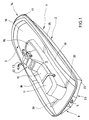
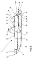
- Jet boat 1 has a substantially flat hull 2 carrying a likewise substantially flat deck 3.
- a jet propulsion system 4 with a jet nozzle 5 opening at the lower stern.
- Jet propulsion system 4 is powered by an engine 6 disposed adjacent the longitudinal center of hull 2, or more accurately, at the center of gravity CG.
- a tank 7 for the fuel supply of engine 6.
- Deck 3 carries a raised seat bench 9 extending for'ards from stern 8.
- Seat bench 9 comprises a driver's seat 10 and a pillion seat 11.
- For'ards of seat bench 9 there is a control cockpit 12 comprising motorcycle-type handlebars 13 connected in a per se known and therefore not detailedly shown manner to jet propulsion system 4.
- Control cockpit 12 is located above center of gravity CG, and thus above engine 6.
- Seat bench 12 extends beyond control cockpit 12 towards the bows 14 so as to form a front seat 15 for'ard of control cockpit 12.
- Formed in deck 3 about seat bench 9 is a gutter 16 defined by coamings 17.
- gutter 16 merges with two foot troughs 18, 19 opening towards stern 8.
- the aft ends of foot troughs 18, 19 are each obturated by a respective transverse body 20 spaced from stern 8 for preventing the inflow of water from the stern.
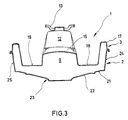
- hull 2 of jet boats 1 is of a combined box-shaped and triangular construction, the bottom side 21 of the substantially rectangular hull bottom 22 being formed with a substantially triangular raised portion 23 extending towards the stern.
- the for'ard portion of hull bottom 22 is substantially box-shaped and relatively flat, whereas the aft portion of hull bottom 22 is of a more or less triangular cross-sectional shape extending to a greater depth.
- the two lateral sides 24 and 25 of hull 2 extend substantially parallel to one another and perpendicular to the lateral edges of bottom 22. In the stopped condition, i.e. with the jet boat 1 adrift, the major part of hull sides 24 and 25 is immersed in the water.
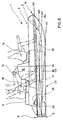
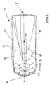
- hull 2 may be even more clearly described with reference to the different waterlines (a) to (e) corresponding to various load and operating conditions. These waterlines are depicted in figs. 6 and 7.
- the waterline (a) applies when driver's seat 10 and pillion seat 11 of seat bench 9 are occupied by two persons and jet boat 1 is under way. In this case the water line substantially circumscribes a triangle as clearly shown in fig. 7.
- a course alteration causes hull 2 to heel, resulting in a corresponding displacement of the waterline.
- This state is depicted in fig. 7 by waterline (b) corresponding to a course alteration to port. It is to be noted that under these conditions the box-shaped bow section of hull 2 remains clear of the water, the waterline (b) being still of a substantially triangular configuration.
- Waterline (c) corresponds to the state in which the two seats 10 and 11 of seat bench 9 are occupied by two persons while jet boat 1 is not under way, i.e. adrift. In this state both sides 24, 25 of hull 2 are immersed to a major part. With the exception of its for'ard portion, waterline (c) circumscribes a substantially rectangular shape in this state. The for'ard portion of waterline (c) encloses an angle ⁇ with its apex centered on the longitudinal centerline CL of jet boat 1.
- Waterline (d) corresponds to the state in which jet boat 1 is adrift and driver's seat 10 and front seat 15 are each occupied by a passenger. It is readily noted that the for'ard portion of waterline (d) has been displaced farther for'ard, resulting in a spreading of the enclosed angle ⁇ ′. The configuration of the waterline thus approaches that of a rectangle still further.
- Teh waterline designated (e) in fig. 6 corresponds to the state that the boat is adrift while only front seat 15 is occupied by a passenger. This state is also depicted in fig. 7, clearly showing that waterline (e) approaches the rectangular shape still further, although bows 14 is immersed somewhat deeper than stern 8. The for'ard portion of waterline (e) now encloses the maximum angle ⁇ ⁇ . Also under these conditions, the major part of the hull's sides 24 and 25 remains immersed.
- the transverse body is formed as a baffle 20 extending transversely of the longitudinal direction of the troughs somewhat for'ard of stern 8.
- Baffle 20 obturates the aft end of the respective foot trough 18, 19 to prevent the inflow of water thereinto from the stern when the latter is deep in the water.
- baffle 20 is located far enough for'ard of stern 8 for not hampering boarding of the boat from the water. Baffle 20 may even be used as a grip ledge to facilitate boarding from the stern.
- the transverse body comprises a resiliently compressible tubular bellows 26 extending transversely of foot troughs 18, 19.
- the non-deformed or relaxed state of bellows 26 is depicted in solid lines.
- the exertion of pressure from above, for instance by pushing downwards with a foot, causes bellows 26 to assume the shape indicated by dotted lines.
- the thus designed transverse body may thus be of a greater height than a rigid body without thereby preventing water that has entered foot troughs 18, 19 from flowing off towards the stern.
- the exertion of sufficient pressure on bellows 26 permits any water to be drained from the foot troughs while the jet boat is under way. To accomplish this effect the drievr or pillion-rider may for instance stand on bellows 26 while the boat is under way.
- the transverse body is formed as a flap mounted for pivoting about a horizontal pivot axis extending transversely of foot troughs 18, 19.
- Flap 28 is biased by a spring element 29 towards the obturating position shown in fig. 6, in which flap 28 prevents the water inflow from the stern into foot troughs 18, 19.
- Spring element 29 may be compressed by stepping onto flap 28 for permitting water already present in foot troughs 18, 19 to flow off towards the stern.
- FIG. 8 and 9 Shown finally in figs. 8 and 9 is an embodiment comprising a transverse body in the form of a buoyant flap 28.
- the aft end portion of each foot trough 18, 19 is provided with a recess 30 of triangular cross-sectional shape extending transversely of deck 3.
- the lowermost portion of recess 30 is provided with a drain opening communicating with a drain pipe 31 extending to the bottom side 21 of the hull's bottom 22 with its mouth opening towards stern 8.
- the for'ard portion of flap 28 is pivotally mounted about a horizontal pivot axis 27 extending transversely of foot troughs 18, 19.
- the two dash-dotted lines (f) and (g) in figs. 8 and 9 illustrate the respective waterline.
- the waterline (f) in fig. 8 corresponds to the normal operating condition, with jet boat 1 under way and driver's seat 10 and pillion seat 11 occupied by two passengers.
- the waterline (g) in fig. 9 corresponds to the state in which jet boat 1 is drifting with stern 8 under excessive load as by a single person aboard occupying pillion seat 11. In this state water flows into recess 30 both from the stern and through drain pipe 31, causing flap 28 to float up. As a result, flap 28 obturates the aft portions of foot troughs 18, 19 to thereby prevent the inflow of water.
- flap 28 When the jet boat is under way, flap 28 is also lowered into recess 30 even when the waterline (f) is not below the lowermost portion of recess 30. This is because when jet boat 1 is under way, an injector pump effect is created at the mouth of drain pipe 31, causing water contained in recess 30 to be drained therefrom, so that flap 28 cannot float up. As soon as the speed of the boat is reduced, the static pressure adjacent the mouth of drain pipe 31 at the bottom side 21 of the hull will rise, as a result of which flap 28 is permitted to float up to thereby obturate the aft end portion of foot troughs 18, 19.
- transverse body 20 All of the described embodiments of the transverse body 20 have in common that the flow-off of water already present in foot troughs 18, 19 is scarcely hampered, while the inflow of water from the stern is substantially prevented. Boarding of jet boat 1 from the water over the stern is not hampered by any of the transverse bodies 20.
Landscapes
- Physics & Mathematics (AREA)
- Fluid Mechanics (AREA)
- Chemical & Material Sciences (AREA)
- Engineering & Computer Science (AREA)
- Combustion & Propulsion (AREA)
- Mechanical Engineering (AREA)
- Ocean & Marine Engineering (AREA)
- Hydraulic Turbines (AREA)
- Harvesting Machines For Specific Crops (AREA)
- Toys (AREA)
Applications Claiming Priority (4)
| Application Number | Priority Date | Filing Date | Title |
|---|---|---|---|
| JP213010/87 | 1987-08-28 | ||
| JP62213010A JP2676345B2 (ja) | 1987-08-28 | 1987-08-28 | 小型滑走艇 |
| JP62220392A JP2666139B2 (ja) | 1987-09-04 | 1987-09-04 | 小型滑走艇 |
| JP220392/87 | 1987-09-04 |
Publications (2)
| Publication Number | Publication Date |
|---|---|
| EP0304822A1 true EP0304822A1 (de) | 1989-03-01 |
| EP0304822B1 EP0304822B1 (de) | 1993-03-03 |
Family
ID=26519571
Family Applications (2)
| Application Number | Title | Priority Date | Filing Date |
|---|---|---|---|
| EP88113521A Expired - Lifetime EP0304821B1 (de) | 1987-08-28 | 1988-08-19 | Düsenboot |
| EP88113522A Expired - Lifetime EP0304822B1 (de) | 1987-08-28 | 1988-08-19 | Strahlboot |
Family Applications Before (1)
| Application Number | Title | Priority Date | Filing Date |
|---|---|---|---|
| EP88113521A Expired - Lifetime EP0304821B1 (de) | 1987-08-28 | 1988-08-19 | Düsenboot |
Country Status (2)
| Country | Link |
|---|---|
| EP (2) | EP0304821B1 (de) |
| ES (2) | ES2043747T3 (de) |
Cited By (2)
| Publication number | Priority date | Publication date | Assignee | Title |
|---|---|---|---|---|
| US4979459A (en) * | 1988-03-09 | 1990-12-25 | Yamaha Hatsudoki Kabushiki Kaisha | Small sized jet propulsion boat |
| US5036789A (en) * | 1990-03-01 | 1991-08-06 | Kelly Roy T | Jet ski hull and method of manufacture |
Families Citing this family (2)
| Publication number | Priority date | Publication date | Assignee | Title |
|---|---|---|---|---|
| FR2664229B1 (fr) * | 1990-07-06 | 1995-07-07 | Zodiac Int | Embarcation, notamment a propulsion par jet d'eau, equipee d'une carene rigide profilee a l'arriere. |
| GB9905427D0 (en) * | 1999-03-09 | 1999-05-05 | Duncan Ian J | Hull for high speed water craft |
Citations (3)
| Publication number | Priority date | Publication date | Assignee | Title |
|---|---|---|---|---|
| US4128072A (en) * | 1977-03-21 | 1978-12-05 | Woodstream Corporation | Power boat hull |
| US4341177A (en) * | 1979-03-29 | 1982-07-27 | Kawasaki Jukogyo Kaikan Kaisha | Small watercraft |
| EP0201326A1 (de) * | 1985-05-08 | 1986-11-12 | Kawasaki Jukogyo Kabushiki Kaisha | Kleines Wasserfahrzeug |
Family Cites Families (4)
| Publication number | Priority date | Publication date | Assignee | Title |
|---|---|---|---|---|
| GB325852A (en) * | 1928-11-30 | 1930-02-28 | Hubert Scott Paine | Improvements in or relating to under-water fittings for motor boats |
| GB1121031A (en) * | 1966-03-01 | 1968-07-24 | Timothy James Bedford | Improvements relating to planing water craft |
| US3790977A (en) * | 1972-01-24 | 1974-02-12 | Germain Bombardier | Hull construction for watercraft |
| DE2222613A1 (de) * | 1972-05-09 | 1973-11-22 | Kurt Bier | Lenzventil mit rueckschlagklappe fuer sportsegelboote |
-
1988
- 1988-08-19 ES ES88113521T patent/ES2043747T3/es not_active Expired - Lifetime
- 1988-08-19 EP EP88113521A patent/EP0304821B1/de not_active Expired - Lifetime
- 1988-08-19 ES ES198888113522T patent/ES2039532T3/es not_active Expired - Lifetime
- 1988-08-19 EP EP88113522A patent/EP0304822B1/de not_active Expired - Lifetime
Patent Citations (3)
| Publication number | Priority date | Publication date | Assignee | Title |
|---|---|---|---|---|
| US4128072A (en) * | 1977-03-21 | 1978-12-05 | Woodstream Corporation | Power boat hull |
| US4341177A (en) * | 1979-03-29 | 1982-07-27 | Kawasaki Jukogyo Kaikan Kaisha | Small watercraft |
| EP0201326A1 (de) * | 1985-05-08 | 1986-11-12 | Kawasaki Jukogyo Kabushiki Kaisha | Kleines Wasserfahrzeug |
Non-Patent Citations (3)
| Title |
|---|
| J.P. COMSTOCK: "Principles of naval architecture", third reprinting, August 1974, pages 99-101, The Society of Naval Architects and Marine Engineers, New York, US * |
| L. LORD: "Naval architecture of planing hulls", pages 100-102, 1946, Cornell Maritime Press, New York, US * |
| R. MUNRO-SMITH: "Notes and examples in naval architecture", pages 94-95, 1965, Edward Arnold (Publishers) Ltd, London, GB * |
Cited By (2)
| Publication number | Priority date | Publication date | Assignee | Title |
|---|---|---|---|---|
| US4979459A (en) * | 1988-03-09 | 1990-12-25 | Yamaha Hatsudoki Kabushiki Kaisha | Small sized jet propulsion boat |
| US5036789A (en) * | 1990-03-01 | 1991-08-06 | Kelly Roy T | Jet ski hull and method of manufacture |
Also Published As
| Publication number | Publication date |
|---|---|
| EP0304821A1 (de) | 1989-03-01 |
| EP0304821B1 (de) | 1993-08-04 |
| ES2039532T3 (es) | 1993-10-01 |
| ES2043747T3 (es) | 1994-01-01 |
| EP0304822B1 (de) | 1993-03-03 |
Similar Documents
| Publication | Publication Date | Title |
|---|---|---|
| US4813365A (en) | Double deadrise with multiple reflex chine boat hull structure and engine mounting system | |
| JP2666139B2 (ja) | 小型滑走艇 | |
| US4341177A (en) | Small watercraft | |
| JPH0274492A (ja) | 小型ジェット推進艇 | |
| JPH10505308A (ja) | ウォータジェット動力式水上艇 | |
| US10926838B2 (en) | Boat aft cockpit extension | |
| US5406904A (en) | Ladder and attachment for water ski | |
| JP3660683B2 (ja) | 水面航行器 | |
| US20140373769A1 (en) | Watercraft hull | |
| US5443026A (en) | Boat hull with aft planing members | |
| US4378747A (en) | Aquatic recreation vehicle | |
| US6289838B2 (en) | Boat | |
| US4893579A (en) | Compact planing type boat | |
| US4958585A (en) | Boat hull | |
| EP0304822A1 (de) | Strahlboot | |
| US9873487B1 (en) | Hybrid running surface boat | |
| US4744325A (en) | Engine compartment and steering arrangement layout for a small watercraft | |
| AU608259B2 (en) | Recreational water vehicle | |
| RU2200107C2 (ru) | Надувная моторная лодка | |
| JP3804044B2 (ja) | 小型船舶用船体 | |
| RU2297359C1 (ru) | Моторное быстроходное судно | |
| JPH0741872B2 (ja) | 小型ジエツト推進艇 | |
| JP2827316B2 (ja) | 小型水上ビークル | |
| JPS62122896A (ja) | 小型ジエツト推進艇 | |
| JPH0764305B2 (ja) | 定深度半潜水式の水面航行船舶 |
Legal Events
| Date | Code | Title | Description |
|---|---|---|---|
| PUAI | Public reference made under article 153(3) epc to a published international application that has entered the european phase |
Free format text: ORIGINAL CODE: 0009012 |
|
| AK | Designated contracting states |
Kind code of ref document: A1 Designated state(s): ES FR IT |
|
| 17P | Request for examination filed |
Effective date: 19890829 |
|
| 17Q | First examination report despatched |
Effective date: 19901203 |
|
| GRAA | (expected) grant |
Free format text: ORIGINAL CODE: 0009210 |
|
| AK | Designated contracting states |
Kind code of ref document: B1 Designated state(s): ES FR IT |
|
| ITF | It: translation for a ep patent filed | ||
| ET | Fr: translation filed | ||
| REG | Reference to a national code |
Ref country code: ES Ref legal event code: FG2A Ref document number: 2039532 Country of ref document: ES Kind code of ref document: T3 |
|
| PLBE | No opposition filed within time limit |
Free format text: ORIGINAL CODE: 0009261 |
|
| STAA | Information on the status of an ep patent application or granted ep patent |
Free format text: STATUS: NO OPPOSITION FILED WITHIN TIME LIMIT |
|
| 26N | No opposition filed | ||
| PGFP | Annual fee paid to national office [announced via postgrant information from national office to epo] |
Ref country code: FR Payment date: 20010810 Year of fee payment: 14 |
|
| PGFP | Annual fee paid to national office [announced via postgrant information from national office to epo] |
Ref country code: ES Payment date: 20010824 Year of fee payment: 14 |
|
| PG25 | Lapsed in a contracting state [announced via postgrant information from national office to epo] |
Ref country code: ES Free format text: LAPSE BECAUSE OF NON-PAYMENT OF DUE FEES Effective date: 20020820 |
|
| PG25 | Lapsed in a contracting state [announced via postgrant information from national office to epo] |
Ref country code: FR Free format text: LAPSE BECAUSE OF NON-PAYMENT OF DUE FEES Effective date: 20030430 |
|
| REG | Reference to a national code |
Ref country code: FR Ref legal event code: ST |
|
| REG | Reference to a national code |
Ref country code: ES Ref legal event code: FD2A Effective date: 20030912 |
|
| PG25 | Lapsed in a contracting state [announced via postgrant information from national office to epo] |
Ref country code: IT Free format text: LAPSE BECAUSE OF NON-PAYMENT OF DUE FEES;WARNING: LAPSES OF ITALIAN PATENTS WITH EFFECTIVE DATE BEFORE 2007 MAY HAVE OCCURRED AT ANY TIME BEFORE 2007. THE CORRECT EFFECTIVE DATE MAY BE DIFFERENT FROM THE ONE RECORDED. Effective date: 20050819 |