EP0304823A2 - Mehrfarben-Thermodrucker - Google Patents
Mehrfarben-Thermodrucker Download PDFInfo
- Publication number
- EP0304823A2 EP0304823A2 EP88113530A EP88113530A EP0304823A2 EP 0304823 A2 EP0304823 A2 EP 0304823A2 EP 88113530 A EP88113530 A EP 88113530A EP 88113530 A EP88113530 A EP 88113530A EP 0304823 A2 EP0304823 A2 EP 0304823A2
- Authority
- EP
- European Patent Office
- Prior art keywords
- color
- printer
- thermal printer
- ink
- ink ribbon
- Prior art date
- Legal status (The legal status is an assumption and is not a legal conclusion. Google has not performed a legal analysis and makes no representation as to the accuracy of the status listed.)
- Granted
Links
- 239000000049 pigment Substances 0.000 claims description 20
- 239000003973 paint Substances 0.000 claims description 11
- 229940000425 combination drug Drugs 0.000 abstract 1
- 238000007639 printing Methods 0.000 description 22
- 238000012545 processing Methods 0.000 description 17
- 239000003086 colorant Substances 0.000 description 9
- 230000004044 response Effects 0.000 description 6
- 239000000463 material Substances 0.000 description 4
- 238000000034 method Methods 0.000 description 3
- 238000007651 thermal printing Methods 0.000 description 3
- 238000010586 diagram Methods 0.000 description 2
- 238000012986 modification Methods 0.000 description 2
- 230000004048 modification Effects 0.000 description 2
- 238000006243 chemical reaction Methods 0.000 description 1
- 239000000203 mixture Substances 0.000 description 1
- 230000002093 peripheral effect Effects 0.000 description 1
Images

Classifications
-
- B—PERFORMING OPERATIONS; TRANSPORTING
- B41—PRINTING; LINING MACHINES; TYPEWRITERS; STAMPS
- B41J—TYPEWRITERS; SELECTIVE PRINTING MECHANISMS, i.e. MECHANISMS PRINTING OTHERWISE THAN FROM A FORME; CORRECTION OF TYPOGRAPHICAL ERRORS
- B41J2/00—Typewriters or selective printing mechanisms characterised by the printing or marking process for which they are designed
- B41J2/315—Typewriters or selective printing mechanisms characterised by the printing or marking process for which they are designed characterised by selective application of heat to a heat sensitive printing or impression-transfer material
- B41J2/32—Typewriters or selective printing mechanisms characterised by the printing or marking process for which they are designed characterised by selective application of heat to a heat sensitive printing or impression-transfer material using thermal heads
- B41J2/325—Typewriters or selective printing mechanisms characterised by the printing or marking process for which they are designed characterised by selective application of heat to a heat sensitive printing or impression-transfer material using thermal heads by selective transfer of ink from ink carrier, e.g. from ink ribbon or sheet
-
- B—PERFORMING OPERATIONS; TRANSPORTING
- B41—PRINTING; LINING MACHINES; TYPEWRITERS; STAMPS
- B41J—TYPEWRITERS; SELECTIVE PRINTING MECHANISMS, i.e. MECHANISMS PRINTING OTHERWISE THAN FROM A FORME; CORRECTION OF TYPOGRAPHICAL ERRORS
- B41J35/00—Other apparatus or arrangements associated with, or incorporated in, ink-ribbon mechanisms
- B41J35/16—Multicolour arrangements
- B41J35/18—Colour change effected automatically
Definitions
- the present invention generally relates to a color thermal printer of a type which utilizes a color ink ribbon having ink areas of different color alternating over the length thereof for the reproduction of a color image on a sheet material.
- an image of a desired color can be obtained on the sheet material by successively transferring thermally fusible ink pigments of different color from a web of pigment carrier, forming a part of the color ink ribbon, onto the sheet material so as to superimpose with each other thereby to permit mixture of these different colors to represent the desired color.
- the term "color thermal printer” herein referred to for the purpose of the present invention should not be construed as limitative of the printer having only the capability of printing an image in a plurality of colors which solely depends on the type of ink ribbon. For example, when a monochromatic, for example, black, ink ribbon is used, the color thermal printer can give a print-out of a black image, but when a multi-color ribbon is used, it can give a print-out of a colored image.
- the illustrated prior art color thermal printer comprises a reader unit including an image scanner 21 for reading, for example, a color document and for providing a data descriptive of the color document and a memory 22 for the storage of the data fed from the image scanner 21, and a printer unit including a printer control 23, a printer drive circuit 24, a thermal printing head 25, a particular color ink ribbon 26, a platen 27 and a platen drive motor 28 drivingly coupled with the platen 27.
- a reader unit including an image scanner 21 for reading, for example, a color document and for providing a data descriptive of the color document and a memory 22 for the storage of the data fed from the image scanner 21, and a printer unit including a printer control 23, a printer drive circuit 24, a thermal printing head 25, a particular color ink ribbon 26, a platen 27 and a platen drive motor 28 drivingly coupled with the platen 27.
- the color ink ribbon 26 utilizable in the color thermal printer is currently available in a number of different types:
- a first one of these types is a three-color ink ribbon comprised of a length of pigment carrier sheet and cyclically alternating ink areas each including three ink layers of three different colors, for example, yellow, magenta and cyan, laid over the entire length thereof.
- a second one of these types is a four-color ink ribbon comprised of a length of pigment carrier sheet and cyclically alternating ink areas each including four ink layers of four different colors, for example, yellow, magenta, cyan and black, laid over the entire length thereof.
- a third one of these types is a monochromatic ink ribbon comprised of a length of pigment carrier sheet and a monochromatic, for example, black, ink layer laid over the entire length thereof.
- the actual printing is carried out by the thermal printing head 25 in dependence on the data supplied from the memory 22.
- the ink ribbon actually mounted is either the first type or the second type, some or all of the pigments of the different colors are successively transferred from the associated ink layers onto a sheet material so as to superimpose one over the other to give a particular color substantially faithful to the color connoted by the data fed from the reader unit to the printer unit.
- the first to third types of ink ribbon referred to above are in practice interchangeably used depending on the purpose for which the printing is desired.
- the user of the thermal printer is required to provide to the printer control instructions indicative of a particular one of these types that is actually loaded on the printer.
- the user of the printer must manually input from a printer control panel to the printer control a command indicative of the particular one of these types of ink ribbon each time one type of ink ribbon is replaced with another one of the types, or the printer will fail to give an intended printing result.
- the present invention has been devised with a view to substantially eliminating the above discussed problem inherent in the prior art color thermal printer and has for its essential object to provide an improved color thermal printer operable with any one of different types of color ink ribbon, wherein an inexpensive means is provided for detecting and automatically providing a particular one of these types that is actually loaded on the printer to the printer control.
- a color thermal printer of a type which utilizes any one of ink ribbons of different color combination, which comprises a different identifier means provided on and peculiar to each of the different ink ribbons and descriptive of the color combination of the respective ink ribbon and a detecting means cooperable with any one of the identifier means for detecting either electrically or optically, and providing an output signal indicative of, one of the ink ribbons of different color combination which is actually mounted on the printer.
- the output signal from the detecting means is utilized to instruct the thermal printer that the ink ribbon of the particular color combination has actually been mounted on the printer and, for this purpose, it may be supplied to the printer control generally used in the thermal printer.
- the detecting means detects either electrically or optically the associated identifier means provided on and peculiar to the second type of ink ribbon thereby to provide the output signal to the printer control wherefore any possible erroneous operation of the printer which would result from the difference between the type of ink ribbon actually mounted and the type of ink ribbon identified by the identifying means can be advantageously avoided.
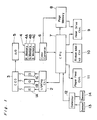
- Fig. 1 which illustrates a color thermal printer embodying the present invention
- the thermal printer shown therein comprises R, G and B light sources 1A, 1B and 1C capable of emitting red, green and blue light beams, respectively, towards a document (not shown); a lighting control circuit 2 adapted to control the R, G and B light sources 1A, 1B and 1C so that the light sources 1A, 1B and 1C can be sequentially and cyclically energized in a time sharing manner to emit the red, green and blue light beams; and a CCD image sensor 3 for sensing the R, G and B light beams which have been sequentially and cyclically reflected from the document and for photoelectrically converting the R, G and B light beams into respective R, G and B read-out signals which are sequentially outputted therefrom.
- R, G and B light sources 1A, 1B and 1C capable of emitting red, green and blue light beams, respectively, towards a document (not shown)
- a lighting control circuit 2
- the R, G and B read-out signals emerging from the image sensor 3 are, after having been converted into respective digital R, G and B read-out signals by an analog-to-digital converter 5, supplied to a memory unit 4 having R, G and B memory areas 4A, 4B and 4C for the storage of the digital R, G and B read-out signals, respectively.
- the memory unit 4 is in turn connected with a color converter 6 operable to perform a color conversion so that the R, G and B colors represented by the associated read-out signals can be converted into yellow, magenta and cyan, or respective signals descriptive of yellow, magenta, cyan and black, respectively, depending on the type of ink ribbon actually mounted on the printer as will be described later.
- the illustrated printer also comprises a central processing unit 7 to which the lighting control circuit 2, the color converter 6, a page memory 8, a thermal printer head drive control circuit 9, a ribbon take-up control circuit 10, a paper feed control circuit 11 and a detector 12 are connected.
- the detector 12 is in turn connected with first and second sensors 13 and 14 both utilized to identify a particular one of the different types of ink ribbons that is actually mounted on the printer in a manner which will now be described.
- each of the different types of ink ribbons generally identified by 15 comprises a strip of pigment carrier 16 secured at its opposite ends to first and second, generally elongated core members 17 and 18.
- Each of these core members has a length greater than the width of the pigment carrier strip 16 so that the opposite ends thereof can protrude axially outwardly from turns of the pigment carrier strip 16 around the respective core member.
- at least one end of each of the core members 17 and 18 has a respective identifier 17A or 18A formed or marked thereon.
- Each identifier 17A or 18A may be in the form of a layer of paint of a particular color, a knurled surface area, or splined grooves, or a combination thereof, which is formed on the peripheral surface of such one end of the respective core member 17 or 18.
- the identifier 17A and 18A on the respective core members 17 and 18 may be identical with or different from each other. More specifically, as can be understood from the subsequent description, in accordance with the present invention, a combination of identical or different identifiers 17A and 18A is utilized to identify a particular type of ink ribbon 15.
- the ink ribbon 15 can be identified as the second type II (four-color ribbon); if the paint layers on the first and second core members 17 and 18 represent a combination of black and white color, the ink ribbon 15 can be identified as the first type I (three-color ribbon); and if they represent a combination of black color, the ink ribbon 15 can be identified as the third type III (monochromatic ribbon). This is tabulated below. Ribbon Type Type II Type I Type III Identifier 17A White Black Black Identifier 18A White White Black
- the first core member 17 is shown to have the identifier 17A in the form of the black paint layer and the second core member 18 is shown to have the identified 18A in the form of the white paint layer, signifying that the illustrated ink ribbon 15 is the first type III of ink ribbon.
- the first type I of ink ribbon is a three-color ink ribbon wherein the pigment carrier strip 16 has cyclically alternating ink areas each including three ink layers of yellow, magenta and cyan deposited over the entire length thereof.
- the second type II of ink ribbon is a four-color ink ribbon wherein the pigment carrier strip 16 has cyclically alternating ink areas each including four ink layers of yellow, magenta, cyan and black deposited over the entire length thereof.
- the third III type of ink ribbon is a monochromatic ink ribbon wherein the pigment carrier strip 16 has a monochromatic, for example, black, ink layer deposited over the entire length thereof. In each of these types I and II except for the third type III, each ink layer has a surface area corresponding to one-page sheet of the document.
- the first sensor 13 is positioned in the vicinity of the identifier 17A on the first core member 17 and includes a light emitter 13A for emitting a beam of light towards the identifier 17A and a light sensing element 13B for sensing the beam of light which has been emitted from the light emitter 13A and subsequently reflected back from the identifier 17A.
- the second sensor 14 is positioned in the vicinity of the identifier 18A on the second core member 18 and includes a light emitter 14A for emitting a beam of light towards the identifier 18A and a light sensing element 14B for sensing the beam of light which has been emitted from the light emitter 14A and subsequently reflected back from the identifier 18A.
- Outputs from the light sensing elements 13B and 14B are applied to the detector 12 by which the type of ink ribbon actually mounted on the printer can be identified in dependence on a combination of the light sensing elements 13B and 14B and, thus, the combination of colors of the identifiers 17A and 18A.
- An output from the detector 12 descriptive of the particular type of ink ribbon detected as actually mounted on the printer is in turn supplied to the central processing unit 7 which may be employed in the form of a microcomputer.
- the central processing unit 7 selects one of a number of color printing modes equal in number to the number of the types of ink ribbons available, for example, three color printing modes so far illustrated, under which the printer can be operated. These color printing modes may include a four-color printing mode, a third-color printing mode and a single color printing mode.
- the central processing unit 7, after having selected one of the color printing modes under which the printer operates, controls the color converter 6, the page memory 8, the head drive control circuit 9, the ribbon take-up control circuit 10 and the paper feed control circuit 11 to make them operate in a manner appropriate to the selected color printing mode so that, in accordance with a known thermal transfer process, ink deposits of different colors in each ink area, or ink deposits of black color, can be transferred from the pigment carrier strip 16 onto a recording paper.
- Y (yellow), M (magenta), C (cyan) and B (black) data are successively introduced from the color converter 6 into the central processing unit 7 and the page memory 8.
- the central processing unit 7 when receiving the Y data instructs the ribbon take-up control 10 to drive one of the core members 17 or 18 of the second type II of ink ribbon to bring the yellow ink layer in one of the ink areas in the pigment carrier strip 16 into alignment with an area of the recording paper which has been brought to a predetermined printing position by the paper feed control 11 in response to a command from the central processing unit 7.
- a thermal printing head is energized to transfer yellow ink deposits onto that area of the recording paper. Similar operations take place in response to the subsequent M, C and B data sequentially supplied to the central processing unit 7 from the color converter 6 and, consequently, the Y, M, C and B ink deposits are transferred onto the same area of the recording paper in superimposed relationship with each other to give a desired color.
- the first and second sensors 13 and 14 detects the identifiers 17A and 18A on the first and second core members 17 and 18, respectively, and the detector 12 processes the respective outputs from the first and second sensors 13 and 14 to provide an intelligence signal necessary to inform the central processing unit 7 of the use of the second type II of ink ribbon so that the central processing unit 7 can, in response to the intelligence signal, set the printer under the corresponding four-color printing mode.
- the first and second sensors 13 and 1 4 detects the identifiers 17A and 18A on the first and second core members 17 and 18, respectively, and the detector 12 processes the respective outputs from the first and second sensors 13 and 14 to provide a different intelligence signal necessary to inform the central processing unit 7 of the use of the first type I of ink ribbon so that the central processing unit 7 can, in response to the different intelligence signal, set the printer under the corresponding three-color printing mode.
- a still different intelligence signal is outputted from the detector 12 to the central processing unit 7 whereby the printer can be set under the single color printing mode.
- each ink layer in each ink area on the pigment carrier strip 16 of any one of the types I to III has been shown and described as having a surface area corresponding to one-page area of the document, it may not be always limited thereto and may be in the form of a band of substantial width extending widthwise of the pigment carrier strip 16.
Landscapes
- Impression-Transfer Materials And Handling Thereof (AREA)
- Electronic Switches (AREA)
Applications Claiming Priority (2)
| Application Number | Priority Date | Filing Date | Title |
|---|---|---|---|
| JP129470/87U | 1987-08-26 | ||
| JP1987129470U JP2557906Y2 (ja) | 1987-08-26 | 1987-08-26 | カラープリンタ |
Publications (3)
| Publication Number | Publication Date |
|---|---|
| EP0304823A2 true EP0304823A2 (de) | 1989-03-01 |
| EP0304823A3 EP0304823A3 (en) | 1989-05-10 |
| EP0304823B1 EP0304823B1 (de) | 1992-04-08 |
Family
ID=15010287
Family Applications (1)
| Application Number | Title | Priority Date | Filing Date |
|---|---|---|---|
| EP88113530A Expired EP0304823B1 (de) | 1987-08-26 | 1988-08-19 | Mehrfarben-Thermodrucker |
Country Status (5)
| Country | Link |
|---|---|
| US (1) | US4910533A (de) |
| EP (1) | EP0304823B1 (de) |
| JP (1) | JP2557906Y2 (de) |
| CA (1) | CA1294488C (de) |
| DE (1) | DE3869868D1 (de) |
Cited By (3)
| Publication number | Priority date | Publication date | Assignee | Title |
|---|---|---|---|---|
| EP0566058A3 (de) * | 1992-04-13 | 1993-11-03 | Sony Corporation | Mehrfarbendrucker |
| EP0555834A3 (en) * | 1992-02-10 | 1993-11-10 | Eastman Kodak Co | Multiweb printer system with end of web responsive control |
| KR19990007340A (ko) * | 1997-06-25 | 1999-01-25 | 이데이 노부유끼 | 프린터 장치 및 인쇄 방법 |
Families Citing this family (13)
| Publication number | Priority date | Publication date | Assignee | Title |
|---|---|---|---|---|
| JP2749075B2 (ja) * | 1988-10-03 | 1998-05-13 | 株式会社日立製作所 | 熱転写記録装置及びインク紙カセット |
| JPH02231184A (ja) * | 1989-03-06 | 1990-09-13 | Tokyo Electric Co Ltd | カラーインクリボンの色判別装置 |
| JP3057532B2 (ja) * | 1992-02-14 | 2000-06-26 | ソニー株式会社 | インクリボンカセット |
| EP0620119A1 (de) * | 1993-04-14 | 1994-10-19 | Agfa-Gevaert N.V. | Erfassung des Typs des Farbstoffgebenden Elementes in einem Thermodruckverfahren |
| JP3362444B2 (ja) * | 1993-05-14 | 2003-01-07 | ソニー株式会社 | プリンタ |
| JPH06328807A (ja) * | 1993-05-20 | 1994-11-29 | Sony Corp | プリンタ |
| US5755519A (en) * | 1996-12-04 | 1998-05-26 | Fargo Electronics, Inc. | Printer ribbon identification sensor |
| US6152625A (en) * | 1999-07-27 | 2000-11-28 | Fargo Electronics, Inc. | Sensor hub for a print ribbon supply roll and method |
| WO2001037208A2 (en) * | 1999-11-12 | 2001-05-25 | Fargo Electronics, Inc. | Sensor for identifying marks on a ribbon |
| USD466150S1 (en) | 2000-09-29 | 2002-11-26 | Brother Industries, Ltd. | Tape cartridge for label printing machine |
| JP2004050812A (ja) * | 2002-05-28 | 2004-02-19 | Dainippon Printing Co Ltd | スプールもしくはカセットおよびそれを用いた識別方法、プリンター |
| EP2047996B1 (de) * | 2007-10-10 | 2010-09-01 | Teac Corporation | Reinigungseinheit und Drucker |
| EP3147132B1 (de) | 2015-09-28 | 2020-04-29 | Assa Abloy AB | Sensor zur identifikation von registrierungsmarkierungen auf einem band |
Family Cites Families (4)
| Publication number | Priority date | Publication date | Assignee | Title |
|---|---|---|---|---|
| US4517590A (en) * | 1981-10-31 | 1985-05-14 | Tokyo Shibaura Denki Kabushiki Kaisha | Color printing apparatus |
| US4590514A (en) * | 1982-07-19 | 1986-05-20 | Canon Kabushiki Kaisha | Color image processing apparatus |
| JPS6067185A (ja) * | 1983-09-22 | 1985-04-17 | Fuji Xerox Co Ltd | 転写型感熱記録装置 |
| JPS6151380A (ja) * | 1984-08-20 | 1986-03-13 | Ricoh Co Ltd | インク媒体の色数自動判別機構 |
-
1987
- 1987-08-26 JP JP1987129470U patent/JP2557906Y2/ja not_active Expired - Lifetime
-
1988
- 1988-08-19 DE DE8888113530T patent/DE3869868D1/de not_active Expired - Lifetime
- 1988-08-19 EP EP88113530A patent/EP0304823B1/de not_active Expired
- 1988-08-23 US US07/235,447 patent/US4910533A/en not_active Expired - Lifetime
- 1988-08-25 CA CA000575726A patent/CA1294488C/en not_active Expired - Lifetime
Cited By (5)
| Publication number | Priority date | Publication date | Assignee | Title |
|---|---|---|---|---|
| EP0555834A3 (en) * | 1992-02-10 | 1993-11-10 | Eastman Kodak Co | Multiweb printer system with end of web responsive control |
| EP0566058A3 (de) * | 1992-04-13 | 1993-11-03 | Sony Corporation | Mehrfarbendrucker |
| US5480237A (en) * | 1992-04-13 | 1996-01-02 | Sony Corporation | Color printer having a ribbon controller |
| KR19990007340A (ko) * | 1997-06-25 | 1999-01-25 | 이데이 노부유끼 | 프린터 장치 및 인쇄 방법 |
| EP0887197A3 (de) * | 1997-06-25 | 2000-05-24 | Sony Corporation | Druckvorrichtung und Druckverfahren |
Also Published As
| Publication number | Publication date |
|---|---|
| EP0304823B1 (de) | 1992-04-08 |
| US4910533A (en) | 1990-03-20 |
| CA1294488C (en) | 1992-01-21 |
| JP2557906Y2 (ja) | 1997-12-17 |
| EP0304823A3 (en) | 1989-05-10 |
| JPS6434264U (de) | 1989-03-02 |
| DE3869868D1 (de) | 1992-05-14 |
Similar Documents
| Publication | Publication Date | Title |
|---|---|---|
| US4910533A (en) | Color thermal printer | |
| KR0157134B1 (ko) | 잉크 시이트 | |
| EP0263871B1 (de) | Farbbereicherkennungsvorrichtung für ein farbband eines thermodruckers | |
| EP0582997B1 (de) | Drucker mit Kompensation von Umgebungseinflüssen | |
| US5095316A (en) | Method for recording a multi-color image on a thermal recording material | |
| EP0566058B1 (de) | Mehrfarbendrucker | |
| US4835603A (en) | Color image reproduction apparatus and a composite light filter and ink ribbon for use therein | |
| JP3200237B2 (ja) | 欠陥ドナー検出方法 | |
| JPS60253565A (ja) | 熱転写記録装置 | |
| EP0325118B1 (de) | Verfahren und Gerät zur Erzeugung von mehrfarbigen Bildern | |
| JP2967254B2 (ja) | 記録装置及び記録方法 | |
| JPH0523339Y2 (de) | ||
| JPH02263680A (ja) | インクカセットおよび熱転写プリンタ | |
| JPH0630452Y2 (ja) | ビデオプリンタ | |
| JPS6076377A (ja) | 多色転写型感熱記録装置 | |
| JPS6096473A (ja) | 熱転写型記録装置 | |
| JP3298074B2 (ja) | カラープリンタ装置 | |
| JPS58209595A (ja) | 熱転写形カラ−プリンタのインクカラ−検知方式 | |
| JP2513030B2 (ja) | カラ―熱転写プリンタ | |
| JPS60228185A (ja) | 多色印字装置 | |
| JPH0638696Y2 (ja) | インクリボン | |
| JPH0650216Y2 (ja) | カラ−インクシ−トの色域判別回路 | |
| JPH04357069A (ja) | 感熱記録装置の転写リボン | |
| JPS61123570A (ja) | カラ−プリンタ | |
| JPS6161882A (ja) | 熱転写カラ−リボン |
Legal Events
| Date | Code | Title | Description |
|---|---|---|---|
| PUAI | Public reference made under article 153(3) epc to a published international application that has entered the european phase |
Free format text: ORIGINAL CODE: 0009012 |
|
| 17P | Request for examination filed |
Effective date: 19880819 |
|
| AK | Designated contracting states |
Kind code of ref document: A2 Designated state(s): DE FR GB |
|
| PUAL | Search report despatched |
Free format text: ORIGINAL CODE: 0009013 |
|
| AK | Designated contracting states |
Kind code of ref document: A3 Designated state(s): DE FR GB |
|
| 17Q | First examination report despatched |
Effective date: 19901024 |
|
| GRAA | (expected) grant |
Free format text: ORIGINAL CODE: 0009210 |
|
| AK | Designated contracting states |
Kind code of ref document: B1 Designated state(s): DE FR GB |
|
| REF | Corresponds to: |
Ref document number: 3869868 Country of ref document: DE Date of ref document: 19920514 |
|
| ET | Fr: translation filed | ||
| PLBE | No opposition filed within time limit |
Free format text: ORIGINAL CODE: 0009261 |
|
| STAA | Information on the status of an ep patent application or granted ep patent |
Free format text: STATUS: NO OPPOSITION FILED WITHIN TIME LIMIT |
|
| 26N | No opposition filed | ||
| REG | Reference to a national code |
Ref country code: GB Ref legal event code: IF02 |
|
| PGFP | Annual fee paid to national office [announced via postgrant information from national office to epo] |
Ref country code: FR Payment date: 20040810 Year of fee payment: 17 |
|
| PGFP | Annual fee paid to national office [announced via postgrant information from national office to epo] |
Ref country code: GB Payment date: 20040818 Year of fee payment: 17 |
|
| PGFP | Annual fee paid to national office [announced via postgrant information from national office to epo] |
Ref country code: DE Payment date: 20040826 Year of fee payment: 17 |
|
| PG25 | Lapsed in a contracting state [announced via postgrant information from national office to epo] |
Ref country code: GB Free format text: LAPSE BECAUSE OF NON-PAYMENT OF DUE FEES Effective date: 20050819 |
|
| PG25 | Lapsed in a contracting state [announced via postgrant information from national office to epo] |
Ref country code: DE Free format text: LAPSE BECAUSE OF NON-PAYMENT OF DUE FEES Effective date: 20060301 |
|
| GBPC | Gb: european patent ceased through non-payment of renewal fee |
Effective date: 20050819 |
|
| PG25 | Lapsed in a contracting state [announced via postgrant information from national office to epo] |
Ref country code: FR Free format text: LAPSE BECAUSE OF NON-PAYMENT OF DUE FEES Effective date: 20060428 |
|
| REG | Reference to a national code |
Ref country code: FR Ref legal event code: ST Effective date: 20060428 |