EP0304827A1 - Régulation de puissance d'une installation à cycle combiné - Google Patents
Régulation de puissance d'une installation à cycle combiné Download PDFInfo
- Publication number
- EP0304827A1 EP0304827A1 EP88113546A EP88113546A EP0304827A1 EP 0304827 A1 EP0304827 A1 EP 0304827A1 EP 88113546 A EP88113546 A EP 88113546A EP 88113546 A EP88113546 A EP 88113546A EP 0304827 A1 EP0304827 A1 EP 0304827A1
- Authority
- EP
- European Patent Office
- Prior art keywords
- steam
- compressor
- turbine
- steam turbine
- preheating
- Prior art date
- Legal status (The legal status is an assumption and is not a legal conclusion. Google has not performed a legal analysis and makes no representation as to the accuracy of the status listed.)
- Granted
Links
- 230000033228 biological regulation Effects 0.000 title abstract description 10
- 230000001105 regulatory effect Effects 0.000 claims abstract description 9
- 238000011084 recovery Methods 0.000 claims description 3
- 238000000034 method Methods 0.000 abstract description 8
- 230000006698 induction Effects 0.000 abstract 3
- 238000010438 heat treatment Methods 0.000 abstract 2
- 239000007789 gas Substances 0.000 description 37
- 239000002918 waste heat Substances 0.000 description 10
- 239000000446 fuel Substances 0.000 description 9
- 238000002485 combustion reaction Methods 0.000 description 4
- 238000000605 extraction Methods 0.000 description 3
- XLYOFNOQVPJJNP-UHFFFAOYSA-N water Substances O XLYOFNOQVPJJNP-UHFFFAOYSA-N 0.000 description 3
- 230000005611 electricity Effects 0.000 description 2
- 230000003993 interaction Effects 0.000 description 2
- 238000004364 calculation method Methods 0.000 description 1
- 239000000969 carrier Substances 0.000 description 1
- 239000003245 coal Substances 0.000 description 1
- 230000006835 compression Effects 0.000 description 1
- 238000007906 compression Methods 0.000 description 1
- 238000009833 condensation Methods 0.000 description 1
- 230000005494 condensation Effects 0.000 description 1
- 239000002826 coolant Substances 0.000 description 1
- 230000007423 decrease Effects 0.000 description 1
- 230000003247 decreasing effect Effects 0.000 description 1
- 230000001419 dependent effect Effects 0.000 description 1
- 238000011161 development Methods 0.000 description 1
- 230000018109 developmental process Effects 0.000 description 1
- 238000010586 diagram Methods 0.000 description 1
- 238000005516 engineering process Methods 0.000 description 1
- 238000001704 evaporation Methods 0.000 description 1
- 230000008020 evaporation Effects 0.000 description 1
- 239000003546 flue gas Substances 0.000 description 1
- 239000012530 fluid Substances 0.000 description 1
- 238000002309 gasification Methods 0.000 description 1
- 238000004519 manufacturing process Methods 0.000 description 1
Images

Classifications
-
- F—MECHANICAL ENGINEERING; LIGHTING; HEATING; WEAPONS; BLASTING
- F02—COMBUSTION ENGINES; HOT-GAS OR COMBUSTION-PRODUCT ENGINE PLANTS
- F02C—GAS-TURBINE PLANTS; AIR INTAKES FOR JET-PROPULSION PLANTS; CONTROLLING FUEL SUPPLY IN AIR-BREATHING JET-PROPULSION PLANTS
- F02C9/00—Controlling gas-turbine plants; Controlling fuel supply in air- breathing jet-propulsion plants
- F02C9/48—Control of fuel supply conjointly with another control of the plant
- F02C9/50—Control of fuel supply conjointly with another control of the plant with control of working fluid flow
- F02C9/54—Control of fuel supply conjointly with another control of the plant with control of working fluid flow by throttling the working fluid, by adjusting vanes
-
- F—MECHANICAL ENGINEERING; LIGHTING; HEATING; WEAPONS; BLASTING
- F01—MACHINES OR ENGINES IN GENERAL; ENGINE PLANTS IN GENERAL; STEAM ENGINES
- F01K—STEAM ENGINE PLANTS; STEAM ACCUMULATORS; ENGINE PLANTS NOT OTHERWISE PROVIDED FOR; ENGINES USING SPECIAL WORKING FLUIDS OR CYCLES
- F01K23/00—Plants characterised by more than one engine delivering power external to the plant, the engines being driven by different fluids
- F01K23/02—Plants characterised by more than one engine delivering power external to the plant, the engines being driven by different fluids the engine cycles being thermally coupled
- F01K23/06—Plants characterised by more than one engine delivering power external to the plant, the engines being driven by different fluids the engine cycles being thermally coupled combustion heat from one cycle heating the fluid in another cycle
- F01K23/10—Plants characterised by more than one engine delivering power external to the plant, the engines being driven by different fluids the engine cycles being thermally coupled combustion heat from one cycle heating the fluid in another cycle with exhaust fluid of one cycle heating the fluid in another cycle
- F01K23/101—Regulating means specially adapted therefor
-
- F—MECHANICAL ENGINEERING; LIGHTING; HEATING; WEAPONS; BLASTING
- F02—COMBUSTION ENGINES; HOT-GAS OR COMBUSTION-PRODUCT ENGINE PLANTS
- F02C—GAS-TURBINE PLANTS; AIR INTAKES FOR JET-PROPULSION PLANTS; CONTROLLING FUEL SUPPLY IN AIR-BREATHING JET-PROPULSION PLANTS
- F02C7/00—Features, components parts, details or accessories, not provided for in, or of interest apart form groups F02C1/00 - F02C6/00; Air intakes for jet-propulsion plants
- F02C7/08—Heating air supply before combustion, e.g. by exhaust gases
-
- Y—GENERAL TAGGING OF NEW TECHNOLOGICAL DEVELOPMENTS; GENERAL TAGGING OF CROSS-SECTIONAL TECHNOLOGIES SPANNING OVER SEVERAL SECTIONS OF THE IPC; TECHNICAL SUBJECTS COVERED BY FORMER USPC CROSS-REFERENCE ART COLLECTIONS [XRACs] AND DIGESTS
- Y02—TECHNOLOGIES OR APPLICATIONS FOR MITIGATION OR ADAPTATION AGAINST CLIMATE CHANGE
- Y02E—REDUCTION OF GREENHOUSE GAS [GHG] EMISSIONS, RELATED TO ENERGY GENERATION, TRANSMISSION OR DISTRIBUTION
- Y02E20/00—Combustion technologies with mitigation potential
- Y02E20/16—Combined cycle power plant [CCPP], or combined cycle gas turbine [CCGT]
- Y02E20/18—Integrated gasification combined cycle [IGCC], e.g. combined with carbon capture and storage [CCS]
Definitions
- the invention relates to the power control of a combined gas / steam turbine power plant, essentially consisting of at least one gas turbine group, a heat recovery steam generator, a steam turbine, a generator and a condenser.
- waste heat steam generator waste heat boiler
- this part-load operation can take place via the fuel regulation by reducing the fuel flow, but at almost constant permanent air flow, the turbine inlet temperature is lowered.
- this type of power control also reaches its limits: at a partial load of 80%, the temperature of the turbine exhaust gases rises to the still permissible maximum value due to the adjustment of the compressor guide vanes; A further reduction in the partial load by adjusting the compressor guide vanes is not recommended in terms of system technology and in the light of the efficiencies that can be achieved with it.
- the invention seeks to remedy this.
- the invention is based on the object of proposing a power control in a combined gas / steam turbine power plant of the type mentioned, in which the load can be reduced to less than 70% with minimal loss of efficiency.
- Preheating the air drawn in by the compressor is suitable for reducing the mass flow rate through the gas turbine, which allows a corresponding reduction in the amount of fuel without the permissible gas temperature falling at the inlet to the turbine. This also results in a very good partial load efficiency for a combination system, provided that the preheating of the compressor air does not use heat that could have been used for steam or electricity production.
- the great advantage of the invention can be seen in the fact that steam is removed from the steam turbine for preheating the compressor air, specifically at a location where the exergetic potential of the steam removed there is only slightly to used up, and consequently the specific electrical output of the steam turbine System is trimmed very weakly. On average, it can be expected that the specific output of the steam turbine will only drop by 1/10 of the energy used for preheating due to this steam extraction.
- Fig. 1 shows the interaction of a combination plant, which consists essentially of a gas turbine group and a steam turbine cycle.
- the non-visible provision of the fuel required to operate the combustion chamber 4 and possibly the waste heat boiler 7 can be accomplished, for example, by coal gasification integrated in the combination system.
- the gas turbine group 1 as an autonomous unit consists of a compressor 2, a gas turbine 3 coupled to it, a combustion chamber 4; There is a connection to a generator 5.
- the sucked-in air 18 is compressed in the compressor 2 and flows via a line as compressed air 20 into the combustion chamber 4.
- the air which has been converted into hot gas 21 in the combustion chamber 4 then acts on the gas turbine 3.
- the gas turbine exhaust gases 22 become consequently no longer blown off, but instead they flow through a waste heat boiler 7, in which the steam generation for the application of a downstream steam turbine 6 is provided by heat exchange.
- the waste heat boiler 7 shown is a two-pressure waste heat boiler.
- an impression waste heat boiler can also be used.
- the latter has the advantage over this that the temperature of the flue gases 29 can be lowered lower, which increases the efficiency of the combination system.
- an additional furnace (not shown) can be added to the waste heat boiler 7, which processes the gas turbine exhaust gases 22 to a higher temperature level.
- the latter arrangement proves to be advantageous if the power output of the combination system has to be increased during load peaks. It is also possible to use a three-pressure waste heat boiler.
- the thermal energy of the gas turbine exhaust gases 22 is therefore mainly used to generate high and low pressure steam 24 which acts on the steam turbine 6. This is advantageously coupled to the same generator 5 of the turbo group 1.
- the potential of the gas turbine exhaust gases 22 can be optimally exploited in such a way that these exhaust gases, which at the end of the Gas turbine process still have a temperature of about 500 ° C, so that can be lowered to about 100 ° C.
- the relaxed steam then flows after leaving the steam turbine 6 into the condenser 9, water or air being able to be used here as the cooling medium. Conveyed by a pump 10, the condensate 23 usually flows into a preheater, not shown, and from here into a feed water tank and degasser, also not shown.
- the condensate After passing through these stages, the condensate is processed to such an extent that it can be returned to the waste heat boiler 7 for renewed evaporation.
- Steam 25 is removed from the steam turbine 6 and sent through a heat exchanger 8, in which the intake air 18 to the compressor 2 of the gas turbine group 1 is mentioned in the heat exchange process. After passing through the heat exchanger 8, the steam, which has now been converted to condensate, is returned to the treatment process via the pump 10.
- a controller 13 takes over the necessary interventions for regulating the power of the combination system.
- the inlet and outlet temperatures 14, 15 of the gas turbine 3 are preferably supplied to the preprogrammed controller 13 as information carriers.
- the controller 13 can thus be preprogrammed for a power control tailored to the respective system, but of course only those controls that come into question guarantee the lowest loss of efficiency, ie allow the greatest possible throttling of the fuel quantity via signal 32 and valve 33 without the permissible turbine inlet temperature dropping.
- the speed can also be regulated.
- the capacity control of the system can either be done by simply adjusting the compressor guide vanes, or by preheating the Intake air 18 to the compressor 2, or also by a combination and control cascade.
- the control cascade is characterized in that an initial adjustment of the compressor guide vanes is preferably followed by preheating the intake air 18. If the system has to be run at partial load by means of a control cascade, a servo motor 12 used to adjust the compressor guide vanes receives a command from the controller 13 to act on the guide vanes. It is entirely sufficient if this adjustment is limited to the preliminary line of the compressor 2. This process is monitored by the controller 13 by continuously calling up the gas temperatures before (14) and after (15) the gas turbine 3.
- a second control stage intervenes, which now continues the power reduction to the compressor 2 by preheating the intake air 18.
- a control valve 11 placed in the steam extraction line 25 downstream of the heat exchanger 8 opens by command 17, so that the vapor flow through the heat exchanger 8 can take place.
- the degree of opening of the valve 11 will only allow water to pass through.
- the steam extraction 25 required for this purpose is carried out at a point 19 of the steam turbine 6, where the exergetic potential of the steam is only slightly to used up.
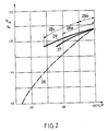
- Curve 26 shows the course of the thermal efficiency in the case of power regulation by means of pure fuel regulation.
- the course of this curve shows quite clearly how the thermal efficiency decreases rapidly during part-load operation.
- a partial load of the combi system of 70% it is only approx. 44%. Operation at partial load is not uncommon in a combination system, and such operation can also extend over a longer period of time. For this very reason, the efficiency to be achieved is often taken as the basis for partial load operation of 75% and below.
- the further curve 27 shows the course of the thermal efficiency through a power control by preheating the intake air to the compressor. It is unmistakable that the efficiency scores significantly better than the previously discussed type of power control.
- the preheating By limiting the preheating to a maximum of 60 ° C - at an outlet temperature of 15 ° C (ISO) - at the compressor inlet, the performance of the combination system can be regulated down to approx. 75% with minimal loss of efficiency. It can be said that with this preheating the permissible increase in the exhaust gas temperature at the gas turbine outlet has not yet been fully utilized, perhaps by around half, for the sake of estimation. Further preheating above about 60 ° C before the compressor is normally not permitted.
- a further reduction in performance down to 67% with a good efficiency curve could, however, be achieved by adjusting the compressor guide vanes, i.e. from a partial load of 75%, the further reduction could be carried out by adjusting the compressor guide vanes.
- the adjustment of the compressor guide vanes results in a somewhat better efficiency than the preheating of the compressor intake air, it is logical to start with the first-mentioned type of control and then to have the type of control intervene by preheating the compressor intake air.
Landscapes
- Engineering & Computer Science (AREA)
- Chemical & Material Sciences (AREA)
- Combustion & Propulsion (AREA)
- Mechanical Engineering (AREA)
- General Engineering & Computer Science (AREA)
- Physics & Mathematics (AREA)
- Fluid Mechanics (AREA)
- Engine Equipment That Uses Special Cycles (AREA)
Applications Claiming Priority (2)
| Application Number | Priority Date | Filing Date | Title |
|---|---|---|---|
| CH3246/87 | 1987-08-24 | ||
| CH324687A CH674547A5 (fr) | 1987-08-24 | 1987-08-24 |
Publications (2)
| Publication Number | Publication Date |
|---|---|
| EP0304827A1 true EP0304827A1 (fr) | 1989-03-01 |
| EP0304827B1 EP0304827B1 (fr) | 1992-05-13 |
Family
ID=4251814
Family Applications (1)
| Application Number | Title | Priority Date | Filing Date |
|---|---|---|---|
| EP19880113546 Expired - Lifetime EP0304827B1 (fr) | 1987-08-24 | 1988-08-20 | Régulation de puissance d'une installation à cycle combiné |
Country Status (4)
| Country | Link |
|---|---|
| EP (1) | EP0304827B1 (fr) |
| JP (1) | JPH01117903A (fr) |
| CH (1) | CH674547A5 (fr) |
| DE (1) | DE3871036D1 (fr) |
Cited By (7)
| Publication number | Priority date | Publication date | Assignee | Title |
|---|---|---|---|---|
| DE19615911A1 (de) * | 1996-04-22 | 1997-10-23 | Asea Brown Boveri | Verfahren zum Betrieb einer Kombianlage |
| DE19621926A1 (de) * | 1996-05-31 | 1997-12-04 | Abb Patent Gmbh | Verfahren zum Anfahren einer Kombi-Kraftwerksanlage bei Netzausfall |
| EP0718470A3 (fr) * | 1994-12-24 | 1999-03-03 | Asea Brown Boveri Ag | Procédé d'opération d'une turbine à gaz |
| EP0953732A3 (fr) * | 1998-04-28 | 2002-06-19 | Mitsubishi Heavy Industries, Ltd. | Centrale combinée |
| EP1884640A1 (fr) * | 2006-08-04 | 2008-02-06 | Siemens Aktiengesellschaft | Procédé de fonctionnement d'une installation de turbine à gaz, unité de commande et installation combinée de turbines à gaz et à vapeur |
| EP2085588A4 (fr) * | 2006-11-21 | 2013-06-26 | Mitsubishi Heavy Ind Ltd | Appareil de régulation de système de chauffage d'air d'admission pour une turbine à gaz |
| DE102007018420B4 (de) | 2006-04-18 | 2022-07-14 | General Electric Co. | System und Verfahren zur Konditionierung einer Gasturbinenzuluft |
Families Citing this family (2)
| Publication number | Priority date | Publication date | Assignee | Title |
|---|---|---|---|---|
| JP4898294B2 (ja) * | 2006-05-24 | 2012-03-14 | 三菱重工業株式会社 | コンバインドサイクルプラントの吸気加熱システム |
| US8001760B2 (en) | 2008-10-09 | 2011-08-23 | Mitsubishi Heavy Industries, Ltd. | Intake air heating system of combined cycle plant |
Citations (7)
| Publication number | Priority date | Publication date | Assignee | Title |
|---|---|---|---|---|
| US3150487A (en) * | 1963-04-08 | 1964-09-29 | Gen Electric | Steam turbine-gas turbine power plant |
| DE2731387A1 (de) * | 1976-07-19 | 1978-01-26 | Hydragon Corp | Gasturbinen-kraftmaschine mit abgas-rezirkulation |
| DE3002615A1 (de) * | 1979-12-05 | 1981-06-11 | BBC AG Brown, Boveri & Cie., Baden, Aargau | Verfahren und einrichtung fuer den teillastbetrieb von kombinierten kraftanlagen |
| GB2141785A (en) * | 1983-06-20 | 1985-01-03 | Gen Electric | Rapid power response turbine |
| US4578944A (en) * | 1984-10-25 | 1986-04-01 | Westinghouse Electric Corp. | Heat recovery steam generator outlet temperature control system for a combined cycle power plant |
| DE3444433A1 (de) * | 1984-12-06 | 1986-06-12 | Hermann Dipl.-Ing. 5401 Kobern-Gondorf Bongers | Gas/dampf-verbundturbine mit zweistufiger abwaermenutzung |
| GB2170555A (en) * | 1985-02-02 | 1986-08-06 | Klaus Knizia | Method and apparatus for driving an electrical power plant |
Family Cites Families (3)
| Publication number | Priority date | Publication date | Assignee | Title |
|---|---|---|---|---|
| JPS58107805A (ja) * | 1981-12-22 | 1983-06-27 | Toshiba Corp | コンバインドサイクル発電用タ−ビンの制御方法 |
| JPS6278407A (ja) * | 1985-10-02 | 1987-04-10 | Hitachi Ltd | 複合サイクルプラントの運転方法 |
| JPS6291609A (ja) * | 1985-10-17 | 1987-04-27 | Hitachi Ltd | 複合発電プラントの系列負荷効率制御装置 |
-
1987
- 1987-08-24 CH CH324687A patent/CH674547A5/de not_active IP Right Cessation
-
1988
- 1988-08-20 DE DE8888113546T patent/DE3871036D1/de not_active Expired - Lifetime
- 1988-08-20 EP EP19880113546 patent/EP0304827B1/fr not_active Expired - Lifetime
- 1988-08-24 JP JP20848788A patent/JPH01117903A/ja active Pending
Patent Citations (7)
| Publication number | Priority date | Publication date | Assignee | Title |
|---|---|---|---|---|
| US3150487A (en) * | 1963-04-08 | 1964-09-29 | Gen Electric | Steam turbine-gas turbine power plant |
| DE2731387A1 (de) * | 1976-07-19 | 1978-01-26 | Hydragon Corp | Gasturbinen-kraftmaschine mit abgas-rezirkulation |
| DE3002615A1 (de) * | 1979-12-05 | 1981-06-11 | BBC AG Brown, Boveri & Cie., Baden, Aargau | Verfahren und einrichtung fuer den teillastbetrieb von kombinierten kraftanlagen |
| GB2141785A (en) * | 1983-06-20 | 1985-01-03 | Gen Electric | Rapid power response turbine |
| US4578944A (en) * | 1984-10-25 | 1986-04-01 | Westinghouse Electric Corp. | Heat recovery steam generator outlet temperature control system for a combined cycle power plant |
| DE3444433A1 (de) * | 1984-12-06 | 1986-06-12 | Hermann Dipl.-Ing. 5401 Kobern-Gondorf Bongers | Gas/dampf-verbundturbine mit zweistufiger abwaermenutzung |
| GB2170555A (en) * | 1985-02-02 | 1986-08-06 | Klaus Knizia | Method and apparatus for driving an electrical power plant |
Non-Patent Citations (2)
| Title |
|---|
| PATENT ABSTRACTS OF JAPAN, Band 10, Nr. 200 (M-498)[2256], 12. Juli 1986; & JP-A-61 43 204 (HITACHI LTD) 01-03-1986 * |
| PATENT ABSTRACTS OF JAPAN, Band 7, Nr. 211 (M-243)[1356], September 1983; & JP-A-58 107 805 (TOKYO SHIBAURA DENKI K.K.) 27-06-1983 * |
Cited By (10)
| Publication number | Priority date | Publication date | Assignee | Title |
|---|---|---|---|---|
| EP0718470A3 (fr) * | 1994-12-24 | 1999-03-03 | Asea Brown Boveri Ag | Procédé d'opération d'une turbine à gaz |
| DE19615911A1 (de) * | 1996-04-22 | 1997-10-23 | Asea Brown Boveri | Verfahren zum Betrieb einer Kombianlage |
| US5884470A (en) * | 1996-04-22 | 1999-03-23 | Asea Brown Boveri Ag | Method of operating a combined-cycle plant |
| EP0808994A3 (fr) * | 1996-04-22 | 1999-09-01 | Asea Brown Boveri Ag | Procédé de fonctionnement d'une centrale combinée |
| DE19621926A1 (de) * | 1996-05-31 | 1997-12-04 | Abb Patent Gmbh | Verfahren zum Anfahren einer Kombi-Kraftwerksanlage bei Netzausfall |
| DE19621926C2 (de) * | 1996-05-31 | 2000-07-27 | Abb Patent Gmbh | Verfahren zum Anfahren einer Kombi-Kraftwerksanlage bei Netzausfall |
| EP0953732A3 (fr) * | 1998-04-28 | 2002-06-19 | Mitsubishi Heavy Industries, Ltd. | Centrale combinée |
| DE102007018420B4 (de) | 2006-04-18 | 2022-07-14 | General Electric Co. | System und Verfahren zur Konditionierung einer Gasturbinenzuluft |
| EP1884640A1 (fr) * | 2006-08-04 | 2008-02-06 | Siemens Aktiengesellschaft | Procédé de fonctionnement d'une installation de turbine à gaz, unité de commande et installation combinée de turbines à gaz et à vapeur |
| EP2085588A4 (fr) * | 2006-11-21 | 2013-06-26 | Mitsubishi Heavy Ind Ltd | Appareil de régulation de système de chauffage d'air d'admission pour une turbine à gaz |
Also Published As
| Publication number | Publication date |
|---|---|
| DE3871036D1 (de) | 1992-06-17 |
| EP0304827B1 (fr) | 1992-05-13 |
| JPH01117903A (ja) | 1989-05-10 |
| CH674547A5 (fr) | 1990-06-15 |
Similar Documents
| Publication | Publication Date | Title |
|---|---|---|
| EP0523467B1 (fr) | Procédé pour opérer une installation à turbines à gaz et à vapeur et installation pour la mise en oeuvre du procédé | |
| EP0436536B1 (fr) | Procede et installation de generation de vapeur au moyen de chaleur perdue | |
| EP2368021B1 (fr) | Générateur de vapeur à récupération de chaleur et procédé pour améliorer le fonctionnement d'un générateur de vapeur à récupération de chaleur | |
| EP0591163B1 (fr) | Installation combinee a turbines a gaz et a vapeur | |
| DE2934340A1 (de) | Verfahren zum abschalten und wiederanfahren eines kombinierten heizkraftwerks | |
| EP0515911B1 (fr) | Méthode pour opérer une installation à turbines à gaz et à vapeur et une installation correspondante | |
| EP0778397A2 (fr) | Procédé d'opération d'une centrale combinée avec une chaudière de récuperation et un consommateur de vapeur | |
| DE19506787B4 (de) | Verfahren zum Betrieb einer Dampfturbine | |
| EP0523466B1 (fr) | Procédé de fonctionnement d'une installation à turbines à gaz et à vapeur et installation pour la mise en oeuvre du procédé | |
| EP0304827B1 (fr) | Régulation de puissance d'une installation à cycle combiné | |
| EP0764768A1 (fr) | Procédé de fonctionnement d'une centrale d'énergie | |
| DE2518353A1 (de) | Regelsystem fuer energieerzeuger | |
| WO2003104629A1 (fr) | Groupe de turbines a gaz | |
| EP1584798B1 (fr) | Méthode et appareil pour la production d'électricité et de chaleur | |
| DE1932721C3 (de) | Dampferzeuger | |
| EP0586425B1 (fr) | Procede de generation d'energie dans une centrale thermique combinee a gaz et a vapeur | |
| CH698282B1 (de) | Kombikraftwerkssystem. | |
| EP0180093A1 (fr) | Centrale thermique | |
| DE3836463C2 (de) | Verfahren und Vorrichtung zur Nutzung der Abwärme eines Prozesses | |
| EP2138677B1 (fr) | Installation de turbines à gaz et à vapeur | |
| DE3734959C2 (fr) | ||
| WO1994004795A1 (fr) | Procede de production d'energie dans une centrale thermique a gaz et a vapeur | |
| DE3520096A1 (de) | Druckgefeuerte wirbelschichtkesselanlage | |
| DE19633579C2 (de) | Verfahren zum Anlaufenlassen eines Kombinationsprozeß-Kraftwerks | |
| DE10124492B4 (de) | Verfahren zum Betrieb eines Kombikraftwerkes bei unterschiedlichen Netzanforderungen |
Legal Events
| Date | Code | Title | Description |
|---|---|---|---|
| PUAI | Public reference made under article 153(3) epc to a published international application that has entered the european phase |
Free format text: ORIGINAL CODE: 0009012 |
|
| AK | Designated contracting states |
Kind code of ref document: A1 Designated state(s): CH DE LI NL SE |
|
| 17P | Request for examination filed |
Effective date: 19890601 |
|
| 17Q | First examination report despatched |
Effective date: 19900322 |
|
| GRAA | (expected) grant |
Free format text: ORIGINAL CODE: 0009210 |
|
| AK | Designated contracting states |
Kind code of ref document: B1 Designated state(s): CH DE LI NL SE |
|
| REF | Corresponds to: |
Ref document number: 3871036 Country of ref document: DE Date of ref document: 19920617 |
|
| PG25 | Lapsed in a contracting state [announced via postgrant information from national office to epo] |
Ref country code: LI Effective date: 19920831 Ref country code: CH Effective date: 19920831 |
|
| PLBE | No opposition filed within time limit |
Free format text: ORIGINAL CODE: 0009261 |
|
| STAA | Information on the status of an ep patent application or granted ep patent |
Free format text: STATUS: NO OPPOSITION FILED WITHIN TIME LIMIT |
|
| REG | Reference to a national code |
Ref country code: CH Ref legal event code: PL |
|
| 26N | No opposition filed | ||
| PGFP | Annual fee paid to national office [announced via postgrant information from national office to epo] |
Ref country code: SE Payment date: 19930723 Year of fee payment: 6 |
|
| PG25 | Lapsed in a contracting state [announced via postgrant information from national office to epo] |
Ref country code: SE Effective date: 19940821 |
|
| EAL | Se: european patent in force in sweden |
Ref document number: 88113546.1 |
|
| EUG | Se: european patent has lapsed |
Ref document number: 88113546.1 |
|
| NLS | Nl: assignments of ep-patents |
Owner name: ALSTOM (SWITZERLAND) LTD |
|
| NLT1 | Nl: modifications of names registered in virtue of documents presented to the patent office pursuant to art. 16 a, paragraph 1 |
Owner name: ABB ASEA BROWN BOVERI LTD. |
|
| PGFP | Annual fee paid to national office [announced via postgrant information from national office to epo] |
Ref country code: NL Payment date: 20030728 Year of fee payment: 16 |
|
| PGFP | Annual fee paid to national office [announced via postgrant information from national office to epo] |
Ref country code: DE Payment date: 20030805 Year of fee payment: 16 |
|
| PG25 | Lapsed in a contracting state [announced via postgrant information from national office to epo] |
Ref country code: NL Free format text: LAPSE BECAUSE OF NON-PAYMENT OF DUE FEES Effective date: 20050301 Ref country code: DE Free format text: LAPSE BECAUSE OF NON-PAYMENT OF DUE FEES Effective date: 20050301 |
|
| NLV4 | Nl: lapsed or anulled due to non-payment of the annual fee |
Effective date: 20050301 |