EP0304840A2 - Propulseur ionique - Google Patents
Propulseur ionique Download PDFInfo
- Publication number
- EP0304840A2 EP0304840A2 EP88113604A EP88113604A EP0304840A2 EP 0304840 A2 EP0304840 A2 EP 0304840A2 EP 88113604 A EP88113604 A EP 88113604A EP 88113604 A EP88113604 A EP 88113604A EP 0304840 A2 EP0304840 A2 EP 0304840A2
- Authority
- EP
- European Patent Office
- Prior art keywords
- sun
- zones
- spacecraft
- particles
- thrust
- Prior art date
- Legal status (The legal status is an assumption and is not a legal conclusion. Google has not performed a legal analysis and makes no representation as to the accuracy of the status listed.)
- Withdrawn
Links
Images
Classifications
-
- H—ELECTRICITY
- H01—ELECTRIC ELEMENTS
- H01J—ELECTRIC DISCHARGE TUBES OR DISCHARGE LAMPS
- H01J27/00—Ion beam tubes
- H01J27/02—Ion sources; Ion guns
- H01J27/24—Ion sources; Ion guns using photo-ionisation, e.g. using laser beam
-
- F—MECHANICAL ENGINEERING; LIGHTING; HEATING; WEAPONS; BLASTING
- F03—MACHINES OR ENGINES FOR LIQUIDS; WIND, SPRING, OR WEIGHT MOTORS; PRODUCING MECHANICAL POWER OR A REACTIVE PROPULSIVE THRUST, NOT OTHERWISE PROVIDED FOR
- F03H—PRODUCING A REACTIVE PROPULSIVE THRUST, NOT OTHERWISE PROVIDED FOR
- F03H1/00—Using plasma to produce a reactive propulsive thrust
- F03H1/0037—Electrostatic ion thrusters
Definitions
- the invention relates to an ion engine for objects in space, preferably in the form of spacecraft.
- the objects for example the spacecraft, have to be in areas in which solar-charged surfaces have a positive charge due to the lack of atmospheric and plasmatic influences.
- comets experience non-gravitational forces when expelling dust and gas, which has also been confirmed, for example, when evaluating observations and numerous measurement data on the comet Halley.
- Such a material ejection, for example on a comet is strongly influenced, if not even triggered, by electrostatic forces.
- the generation of such non-gravitational forces, for example on spacecraft, can be used to drive them.
- the aim of the invention is therefore to provide a particularly inexpensive to produce ion engine that is largely maintenance-free and extremely reliable. According to the invention, this is achieved in an ion engine for objects in space, preferably in the form of spacecraft, by the features in claim 1.
- Advantageous developments of the invention are the subject of dependent claims.
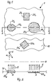
- a surface 10 of a spacecraft 1 is a permanent loading exposed to radiation from an only indicated sun S.
- the surface of the spacecraft 1 is shown bright in Fig.1, while hatched, arbitrarily shaped areas 211 to 21 n of surface zones 201 to 20 n are designated for an exit of positively charged by the sun radiation material particles, which with an easily removable and Ionizable material 3 in the form of very small particles, such as preferably dust particles, or in the form of easily evaporable gas are provided in a sufficient amount.
- the shape, number and size of the dust-bearing surface zones 20 1 to 20 n are arbitrary.
- the entire surface 10 of the spacecraft 1 can be formed by dust carriers, provided that it is ensured that the potential required for acceleration does not collapse due to an excessively large particle flow, but can be maintained.
- Suitable dust particles are, for example, macromolecules (polyvinyl, polypeptide, etc.) with low mutual adhesion, which are easily ionizable.
- the dust particles consist predominantly of a C-H-O-N compound with different chemical structures. Silicate particles, metal particles, etc. also occur. Most of these particles have an equivalent molecular weight of> 10,000, or a mass m of m ⁇ 10 ⁇ 20 kg. Although the use of other particles in the invention should not be excluded, the use of dust particles of this type is preferred.
- a dashed radiation and dust-permeable cover of the dust container for example in the form of grids, is entered at the top of two schematically represented dust containers 222 and 223.
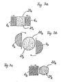
- a cover can also be designed, for example, as a closable diaphragm arrangement shown schematically in FIGS. 3a to 3c if the thrust strength of the ion engine according to the invention is to be controllable accordingly.
- Such diaphragm arrangements for varying the thrust strength can be designed as desired.
- they can take the form of pinholes, as is common with camera lenses.
- you can, for example, as shown schematically in Fig.3a, have the shape of mutually displaceable, for example rectangular diaphragms 6 1, the displaceability of which is indicated with respect to the opening 21 1 by arrows 6 1 above the diaphragm.
- diaphragm arrangements as indicated schematically in Fig.3b, can be designed as semicircular diaphragm parts 63, which can be pivoted to cover all or part of the opening 213, for example, in a direction indicated by the above and below the diaphragm part 63.
- an aperture arrangement as indicated in FIG. 3c, can also be a rectangular ges aperture part 62 be formed, which can be pushed in a direction indicated by an arrow above the aperture part 62 arrow over the opening 212.
- So-called grid apertures can also be used. If the diaphragm assemblies 61 to 63 cover parts of the dust-free areas below, if they are completely or partially open, the generation of charges is not affected because self-charges are emitted from the surface of the diaphragm assemblies 61 to 63.
- the UV component ⁇ of this solar radiation leads to the detachment of electrons via the so-called external photo effect, ie to the positive charging of the surface F and thereby to the formation of a space charge 4 in front of the sunlit side of the surface F (10).
- the potential U has a maximum if no shear-generating ions are released. However, the more ions are accelerated, the more the potential decreases.
- the optimum to be aimed not only depends on the area ratio of the surface zones 20 1 to 20 n, for example in the form of depressions 2 or elevations 7, to the entire sun-exposed area 10, but also on various materials, such as the metal surface, the dust quality, etc ..
- openings 212 in elevations 7 even offer the advantage that there the electric field strength is somewhat higher than over the smooth surface 10. That is, because of the greater force acting there on the dust particles increases accordingly the particle flow. In extreme cases, a tip could even be taken to maximize the electric field. However, this does not increase the overall performance of the engine.
- the achievable thrust can be estimated by inserting corresponding numerical values into the Eqs. 1 to 5 shown above.
- the solar constant in 1 AU is 1.4 x 10³ Wm ⁇ 2.
- I 14 W.
- U0 A / e ⁇ 4V
- N e ⁇ 1019 m ⁇ 2.s ⁇ 1 and thus N ⁇ 1019m ⁇ 2.s ⁇ 1 is obtained .
- the quantum efficiency ⁇ ' has not yet been taken into account. For technical surfaces, it is between 1 and 10%.
- the ratio of the area of the depressions 2 1 to 2 n for ionized particles to the total area is chosen to be 10%, the result is - based on the total area - N ⁇ 1016 m ⁇ 2.s ⁇ 1.
- the thrust of a passive ion engine according to the invention can be changed in a simple manner in that a diaphragm arrangement which is adjustable in inclination but not shown in more detail is attached above the sun-irradiated surface 10.
- a diaphragm arrangement which is adjustable in inclination but not shown in more detail is attached above the sun-irradiated surface 10.
- the zones 20 1 to 20 n providing the ions in the sun-irradiated area 10 can be approximately round or angular, as indicated in FIG. 1. Although planes that are as flat as possible are preferred, curved or convoluted areas with the required dimensions are also possible depending on the thrust required or to be achieved.
- the color of the sun-exposed surfaces 10 also plays a role in that the temperature of the surfaces 10 is directly determined by the color and thus also the work function A of the electrons is directly influenced. Furthermore, the temperature plays an important role for the evaporation rate of the ionizable substance 3 selected as the fuel, for example the finest dust from organic or inorganic materials.
- zones 20 1 to 20 n in the sun-exposed area which serve to accommodate the fuel material 3 in the form of easily removable and thus ionizable material particles or gas particles, is largely as desired, according to an advantageous development of the invention, the continuous supply or loading of these zones 20 1 to 20 n , which may have the form of elevations 7 or depressions 2 1 to 2 n of the sun-exposed surface, for example, from the interior of the spacecraft 1.
- the shape, arrangement and design of the orifice arrangement 6 1 to 6 3 should be largely arbitrary in order to reduce and control the thrust of the passive engine from spacecraft 1, the corresponding control commands being either transmitted by radio or automatically determined on board.
Landscapes
- Engineering & Computer Science (AREA)
- Chemical & Material Sciences (AREA)
- Combustion & Propulsion (AREA)
- Physics & Mathematics (AREA)
- Plasma & Fusion (AREA)
- Mechanical Engineering (AREA)
- General Engineering & Computer Science (AREA)
- Optics & Photonics (AREA)
- Physical Vapour Deposition (AREA)
- Electron Sources, Ion Sources (AREA)
- Elimination Of Static Electricity (AREA)
Applications Claiming Priority (2)
| Application Number | Priority Date | Filing Date | Title |
|---|---|---|---|
| DE3728011 | 1987-08-22 | ||
| DE19873728011 DE3728011A1 (de) | 1987-08-22 | 1987-08-22 | Ionentriebwerk |
Publications (2)
| Publication Number | Publication Date |
|---|---|
| EP0304840A2 true EP0304840A2 (fr) | 1989-03-01 |
| EP0304840A3 EP0304840A3 (fr) | 1989-08-09 |
Family
ID=6334243
Family Applications (1)
| Application Number | Title | Priority Date | Filing Date |
|---|---|---|---|
| EP88113604A Withdrawn EP0304840A3 (fr) | 1987-08-22 | 1988-08-22 | Propulseur ionique |
Country Status (2)
| Country | Link |
|---|---|
| EP (1) | EP0304840A3 (fr) |
| DE (1) | DE3728011A1 (fr) |
Cited By (1)
| Publication number | Priority date | Publication date | Assignee | Title |
|---|---|---|---|---|
| US7773362B1 (en) | 2007-03-07 | 2010-08-10 | The United States Of America As Represented By The Administrator Of The National Aeronautics And Space Administration | Accelerator system and method of accelerating particles |
Families Citing this family (3)
| Publication number | Priority date | Publication date | Assignee | Title |
|---|---|---|---|---|
| DE4410833A1 (de) * | 1994-03-29 | 1995-10-05 | Andreas Tiedemann | Ionisations Antrieb für Motoren und Schwebe, Flugkörper, geeignet für Luft und Raumfahrt |
| DE19708658B4 (de) * | 1997-03-04 | 2004-08-05 | Deutsches Zentrum für Luft- und Raumfahrt e.V. | Verfahren zum Sortieren und/oder Selektieren von bezüglich ihrer Masse, Größe und/oder Oberflächenbeschaffenheiten unterschiedlichen Partikeln |
| DE102012016225A1 (de) | 2012-08-14 | 2014-03-13 | Jürgen Blum | Elektro-Feldenergie auf der Basis von zweidimensionalen Elektronensystemen, mit der Energiemasse in dem koaxialen Leitungs- und Spulensystem des koaxialen Generators und Transformators |
Family Cites Families (4)
| Publication number | Priority date | Publication date | Assignee | Title |
|---|---|---|---|---|
| US3380249A (en) * | 1966-02-21 | 1968-04-30 | Physies Technology Lab Inc | Propulsive device |
| DE1282199B (de) * | 1966-07-28 | 1968-11-07 | Bbc Brown Boveri & Cie | Verfahren zum Beschleunigen von Materie |
| DE1933409A1 (de) * | 1969-07-01 | 1971-01-14 | Inst Plasmaphysik Gmbh | Ionentriebwerk |
| DE2350719A1 (de) * | 1973-10-10 | 1975-04-24 | Deutsche Forsch Luft Raumfahrt | Plasma-ablationstriebwerk zur steuerung von raumflugkoerpern |
-
1987
- 1987-08-22 DE DE19873728011 patent/DE3728011A1/de active Granted
-
1988
- 1988-08-22 EP EP88113604A patent/EP0304840A3/fr not_active Withdrawn
Cited By (1)
| Publication number | Priority date | Publication date | Assignee | Title |
|---|---|---|---|---|
| US7773362B1 (en) | 2007-03-07 | 2010-08-10 | The United States Of America As Represented By The Administrator Of The National Aeronautics And Space Administration | Accelerator system and method of accelerating particles |
Also Published As
| Publication number | Publication date |
|---|---|
| EP0304840A3 (fr) | 1989-08-09 |
| DE3728011C2 (fr) | 1990-07-05 |
| DE3728011A1 (de) | 1989-03-02 |
Similar Documents
| Publication | Publication Date | Title |
|---|---|---|
| EP0106154B1 (fr) | Objectif déflecteur de faisceau de particules neutres à forme variable et procédé pour son utilisation | |
| DE4225169A1 (de) | Verfahren und Vorrichtung zur Erzeugung von Agglomeratstrahlen | |
| DE212019000352U1 (de) | Schubvorrichtung | |
| EP0304840A2 (fr) | Propulseur ionique | |
| EP1110234A1 (fr) | Dispositif et procede pour appliquer un revetement sur des substrats sous vide | |
| DE2146941A1 (de) | Strahlenformungs- und Abbildungssystem | |
| CH639798A5 (de) | Roentgenroehre mit einer elektronenkanone. | |
| DE3136787A1 (de) | "verfahren und vorrichtung zum verstaerkten neutralisieren eines positiv geladenen ionenstrahls" | |
| DE2759043A1 (de) | Sonnenenergieumwandler | |
| DE3513633C2 (de) | Vorrichtung zur Entschwefelung und Denitrierung von Rauchgasen durch Elektronenbestrahlung | |
| EP0515352A1 (fr) | Source d'ions | |
| DD275861A5 (de) | Verfahren und Vorrichtung zur Abscheidung einer dünnen Schicht auf einem transparenten Stoff, insbesondere auf Glas | |
| DE112006001005T5 (de) | Verdampfungsvorrichtung | |
| DE1920183A1 (de) | Ionenbeschussverfahren | |
| DE3014785A1 (de) | Monochromator fuer geladene teilchen | |
| DE3124987A1 (de) | Oberflaechenbehandlungsverfahren und -vorrichtung | |
| DE1491307B2 (de) | Elektronenstrahlerzeugersystem fuer eine laufzeitroehre | |
| DE68913920T2 (de) | Dampf- und Ionenquelle. | |
| DE1591177B1 (de) | Faltbarer reflektor fuer elektromagnetische wellen | |
| DE19848737A1 (de) | Lage- und Bahnregelung von Satelliten | |
| DE1589634A1 (de) | Verfahren und Vorrichtung zum Beschiessen einer Treffplatte mit einem Buendel celadener Teilchen | |
| DE2633190C3 (de) | Ionenquelle | |
| DE1591177C (de) | Faltbarer Reflektor für elektromagnetische Wellen | |
| DE1456205A1 (de) | Orientierungseinrichtung fuer Weltraumflugkoerper | |
| DE740115C (de) | Fernsehbildfaenger mit Halbleiter-Bildwurfelektrode |
Legal Events
| Date | Code | Title | Description |
|---|---|---|---|
| PUAI | Public reference made under article 153(3) epc to a published international application that has entered the european phase |
Free format text: ORIGINAL CODE: 0009012 |
|
| AK | Designated contracting states |
Kind code of ref document: A2 Designated state(s): DE FR GB |
|
| PUAL | Search report despatched |
Free format text: ORIGINAL CODE: 0009013 |
|
| AK | Designated contracting states |
Kind code of ref document: A3 Designated state(s): DE FR GB |
|
| RAP1 | Party data changed (applicant data changed or rights of an application transferred) |
Owner name: DEUTSCHE FORSCHUNGSANSTALT FUER LUFT- UND RAUMFAHR |
|
| 17P | Request for examination filed |
Effective date: 19891230 |
|
| STAA | Information on the status of an ep patent application or granted ep patent |
Free format text: STATUS: THE APPLICATION HAS BEEN WITHDRAWN |
|
| 17Q | First examination report despatched |
Effective date: 19910927 |
|
| 18W | Application withdrawn |
Withdrawal date: 19910925 |
|
| RAP1 | Party data changed (applicant data changed or rights of an application transferred) |
Owner name: DEUTSCHES ZENTRUM FUER LUFT- UND RAUMFAHRT E.V. |