EP0304877A1 - Wärmeaustauscher für eine Brennstoffzellenkraftanlage mit Umformer - Google Patents
Wärmeaustauscher für eine Brennstoffzellenkraftanlage mit Umformer Download PDFInfo
- Publication number
- EP0304877A1 EP0304877A1 EP88113722A EP88113722A EP0304877A1 EP 0304877 A1 EP0304877 A1 EP 0304877A1 EP 88113722 A EP88113722 A EP 88113722A EP 88113722 A EP88113722 A EP 88113722A EP 0304877 A1 EP0304877 A1 EP 0304877A1
- Authority
- EP
- European Patent Office
- Prior art keywords
- housing
- heat exchanger
- steam
- conduit means
- inlet
- Prior art date
- Legal status (The legal status is an assumption and is not a legal conclusion. Google has not performed a legal analysis and makes no representation as to the accuracy of the status listed.)
- Granted
Links
- 239000000446 fuel Substances 0.000 title claims abstract description 44
- 239000002826 coolant Substances 0.000 claims abstract description 23
- 239000002737 fuel gas Substances 0.000 claims abstract description 15
- 239000000203 mixture Substances 0.000 claims abstract description 10
- 238000010926 purge Methods 0.000 claims abstract description 4
- XLYOFNOQVPJJNP-UHFFFAOYSA-N water Substances O XLYOFNOQVPJJNP-UHFFFAOYSA-N 0.000 claims description 21
- 239000004215 Carbon black (E152) Substances 0.000 claims description 17
- 229930195733 hydrocarbon Natural products 0.000 claims description 17
- 150000002430 hydrocarbons Chemical class 0.000 claims description 17
- 239000007789 gas Substances 0.000 claims description 12
- 238000000034 method Methods 0.000 claims description 6
- 239000012530 fluid Substances 0.000 claims description 2
- 230000003134 recirculating effect Effects 0.000 claims 1
- 238000006243 chemical reaction Methods 0.000 abstract description 3
- 230000036647 reaction Effects 0.000 abstract 1
- 238000009833 condensation Methods 0.000 description 3
- 230000005494 condensation Effects 0.000 description 3
- 239000000470 constituent Substances 0.000 description 3
- UFHFLCQGNIYNRP-UHFFFAOYSA-N Hydrogen Chemical compound [H][H] UFHFLCQGNIYNRP-UHFFFAOYSA-N 0.000 description 2
- ATUOYWHBWRKTHZ-UHFFFAOYSA-N Propane Chemical compound CCC ATUOYWHBWRKTHZ-UHFFFAOYSA-N 0.000 description 2
- 239000001257 hydrogen Substances 0.000 description 2
- 229910052739 hydrogen Inorganic materials 0.000 description 2
- VNWKTOKETHGBQD-UHFFFAOYSA-N methane Chemical compound C VNWKTOKETHGBQD-UHFFFAOYSA-N 0.000 description 2
- 238000002407 reforming Methods 0.000 description 2
- 238000000429 assembly Methods 0.000 description 1
- 230000000712 assembly Effects 0.000 description 1
- 239000003054 catalyst Substances 0.000 description 1
- 230000003197 catalytic effect Effects 0.000 description 1
- 230000003750 conditioning effect Effects 0.000 description 1
- 230000005611 electricity Effects 0.000 description 1
- 238000003487 electrochemical reaction Methods 0.000 description 1
- 238000010438 heat treatment Methods 0.000 description 1
- 239000003921 oil Substances 0.000 description 1
- 239000001294 propane Substances 0.000 description 1
- 238000000926 separation method Methods 0.000 description 1
Images


Classifications
-
- F—MECHANICAL ENGINEERING; LIGHTING; HEATING; WEAPONS; BLASTING
- F28—HEAT EXCHANGE IN GENERAL
- F28D—HEAT-EXCHANGE APPARATUS, NOT PROVIDED FOR IN ANOTHER SUBCLASS, IN WHICH THE HEAT-EXCHANGE MEDIA DO NOT COME INTO DIRECT CONTACT
- F28D7/00—Heat-exchange apparatus having stationary tubular conduit assemblies for both heat-exchange media, the media being in contact with different sides of a conduit wall
- F28D7/0066—Multi-circuit heat-exchangers, e.g. integrating different heat exchange sections in the same unit or heat-exchangers for more than two fluids
- F28D7/0083—Multi-circuit heat-exchangers, e.g. integrating different heat exchange sections in the same unit or heat-exchangers for more than two fluids with units having particular arrangement relative to a supplementary heat exchange medium, e.g. with interleaved units or with adjacent units arranged in common flow of supplementary heat exchange medium
-
- F—MECHANICAL ENGINEERING; LIGHTING; HEATING; WEAPONS; BLASTING
- F22—STEAM GENERATION
- F22B—METHODS OF STEAM GENERATION; STEAM BOILERS
- F22B33/00—Steam-generation plants, e.g. comprising steam boilers of different types in mutual association
- F22B33/18—Combinations of steam boilers with other apparatus
-
- F—MECHANICAL ENGINEERING; LIGHTING; HEATING; WEAPONS; BLASTING
- F28—HEAT EXCHANGE IN GENERAL
- F28D—HEAT-EXCHANGE APPARATUS, NOT PROVIDED FOR IN ANOTHER SUBCLASS, IN WHICH THE HEAT-EXCHANGE MEDIA DO NOT COME INTO DIRECT CONTACT
- F28D7/00—Heat-exchange apparatus having stationary tubular conduit assemblies for both heat-exchange media, the media being in contact with different sides of a conduit wall
- F28D7/0066—Multi-circuit heat-exchangers, e.g. integrating different heat exchange sections in the same unit or heat-exchangers for more than two fluids
-
- F—MECHANICAL ENGINEERING; LIGHTING; HEATING; WEAPONS; BLASTING
- F28—HEAT EXCHANGE IN GENERAL
- F28D—HEAT-EXCHANGE APPARATUS, NOT PROVIDED FOR IN ANOTHER SUBCLASS, IN WHICH THE HEAT-EXCHANGE MEDIA DO NOT COME INTO DIRECT CONTACT
- F28D7/00—Heat-exchange apparatus having stationary tubular conduit assemblies for both heat-exchange media, the media being in contact with different sides of a conduit wall
- F28D7/08—Heat-exchange apparatus having stationary tubular conduit assemblies for both heat-exchange media, the media being in contact with different sides of a conduit wall the conduits being otherwise bent, e.g. in a serpentine or zig-zag
- F28D7/082—Heat-exchange apparatus having stationary tubular conduit assemblies for both heat-exchange media, the media being in contact with different sides of a conduit wall the conduits being otherwise bent, e.g. in a serpentine or zig-zag with serpentine or zig-zag configuration
- F28D7/085—Heat-exchange apparatus having stationary tubular conduit assemblies for both heat-exchange media, the media being in contact with different sides of a conduit wall the conduits being otherwise bent, e.g. in a serpentine or zig-zag with serpentine or zig-zag configuration in the form of parallel conduits coupled by bent portions
-
- H—ELECTRICITY
- H01—ELECTRIC ELEMENTS
- H01M—PROCESSES OR MEANS, e.g. BATTERIES, FOR THE DIRECT CONVERSION OF CHEMICAL ENERGY INTO ELECTRICAL ENERGY
- H01M8/00—Fuel cells; Manufacture thereof
- H01M8/04—Auxiliary arrangements, e.g. for control of pressure or for circulation of fluids
- H01M8/04007—Auxiliary arrangements, e.g. for control of pressure or for circulation of fluids related to heat exchange
- H01M8/04029—Heat exchange using liquids
-
- H—ELECTRICITY
- H01—ELECTRIC ELEMENTS
- H01M—PROCESSES OR MEANS, e.g. BATTERIES, FOR THE DIRECT CONVERSION OF CHEMICAL ENERGY INTO ELECTRICAL ENERGY
- H01M8/00—Fuel cells; Manufacture thereof
- H01M8/06—Combination of fuel cells with means for production of reactants or for treatment of residues
- H01M8/0606—Combination of fuel cells with means for production of reactants or for treatment of residues with means for production of gaseous reactants
- H01M8/0612—Combination of fuel cells with means for production of reactants or for treatment of residues with means for production of gaseous reactants from carbon-containing material
-
- Y—GENERAL TAGGING OF NEW TECHNOLOGICAL DEVELOPMENTS; GENERAL TAGGING OF CROSS-SECTIONAL TECHNOLOGIES SPANNING OVER SEVERAL SECTIONS OF THE IPC; TECHNICAL SUBJECTS COVERED BY FORMER USPC CROSS-REFERENCE ART COLLECTIONS [XRACs] AND DIGESTS
- Y02—TECHNOLOGIES OR APPLICATIONS FOR MITIGATION OR ADAPTATION AGAINST CLIMATE CHANGE
- Y02E—REDUCTION OF GREENHOUSE GAS [GHG] EMISSIONS, RELATED TO ENERGY GENERATION, TRANSMISSION OR DISTRIBUTION
- Y02E60/00—Enabling technologies; Technologies with a potential or indirect contribution to GHG emissions mitigation
- Y02E60/30—Hydrogen technology
- Y02E60/50—Fuel cells
Definitions
- This invention relates to a heat exchange assembly for use in a fuel cell power plant, and more particularly, to a heat exchanger which utilizes heat from reformed power plant fuel to preheat raw fuel and to superheat steam prior to mixing the raw fuel and the steam in the reformer.
- the fuel which is used in the electrochemical generation of electricity in commercial forms of fuel cell power plants is catalytically converted or reformed from a raw hydrocarbon fuel, such as methane, propane, naphtha, heating oils or the like, to a hydrogen-enriched fuel gas.
- a raw hydrocarbon fuel such as methane, propane, naphtha, heating oils or the like
- the fuel-steam mixture is then passed through catalyst beds in the reformer where it is catalytically converted to the hydrogen-enriched fuel gas used in the electrochemical reaction.
- the steam used in this reaction will preferably be superheated so as to ensure that no condensation will occur.
- the steam which is used in this reaction may be derived from the water coolant which is used to cool the fuel cell stacks in the power plant.
- the superheating of the steam and the preheating of the raw hydrocarbon fuel is accomplished in the prior art by the use of separate heat exchangers which, once operation of the power plant has begun, derive their heat from reformer burners. These heat exchangers must be preheated for startup by electric heaters to ensure that no water will enter the reformer from the steam core, and to ensure that any condensed water in the reformer effluent lines is evaporated before the reformer begins to produce new reformed fuel.
- the heat exchanger of this invention is a multifunctional device which performs four different heat exchange functions with three different flow cores contained in a single housing. All of the flow cores are thermally interconnected by heat transfer fin plates.
- the heat exchanger of this invention reduces the temperature of the reformer effluent fuel gas to temperatures suitable for the shift converter operation which precedes transferring the fuel gas to the stack. This heat exchanger also produces some of the steam used in the reformer, superheats the steam and preheats the raw hydrocarbon fuel prior to reforming the latter.
- the heat exchanger of this invention is brought to operating temperatures on startup by coolant from the stack and by purging steam, thus obviating the need for separate electric startup heaters.
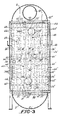
- the heat exchanger denoted generally by the numeral 2 has a single housing 4 with an upper inlet shroud 6 and a lower outlet shroud 8.
- An inlet pipe 10 carries hot reformer effluent from the catalytic reformer (not shown) to the inlet shroud 6.
- An inlet baffle 12 is interposed between the interior of the inlet shroud 6 and the interior of the housing 4 and is operable to evenly distribute the gases flowing into the housing 4 so that the temperatures will be evenly distributed over the heat exchange core portion in the housing 4.
- the interior of the housing 4 is divided into a central core portion 14 through which hot gases can flow from the inlet shroud 6 to the outlet shroud 8, and manifold and flow reversal chambers 16 and 18 on either side of the core portion 14.
- the chambers 16 and 18 are closed off from the core portion 14 by end plates 20.
- An outlet baffle 22 controls the flow rate of the reformed fuel gas from the core portion 14 to the outlet shroud 8.
- the core portion 14 of the assembly is filled with heat exchange fin plates 26, which plates 26, as shown in Fig. 4, are divided into three columns 26′, 26 ⁇ and 26′′′.
- a portion of the power plant coolant water is brought to the heat exchanger 2 via inlet conduit 28 which opens into a coolant water inlet manifold 30 in the housing 4.
- the heat exchange tubes 34 pass through the fin plates in the column 26′′′; the tubes 34′ pass through the fin plates in the column 26 ⁇ ; and the tubes 34 ⁇ pass through the fin plates in the column 26′.
- the coolant water tube pairs 34, 34′ and 34 ⁇ empty into an outlet manifold 36 through ports 38, 38′ and 38 ⁇ .
- the outlet manifold 36 empties into a conduit 38 which delivers the resultant water-steam mixture to a steam separator (not shown), where the steam phase is separated from the water phase.
- the steam phase 38 is then returned from the separator, along with additional process steam, to the heat exchanger 2 through conduit 40 which opens into a steam inlet manifold 42 inside of the housing 4.
- There are three exit openings 44, 44′ and 44 ⁇ in the steam inlet manifold 42 which open into heat exchange tubes 46, 46′ and 46 ⁇ respectively.
- the tube 46 passes through the fin plate column 26′′′; the tube 46′ passes through the fin plate column 26 ⁇ ; and the tube 46 ⁇ passes through the fin plate column 26′.
- the tubes 46, 46′ and 46 ⁇ follow a serpentine path with vertical bends 48 (shown in Fig. 3) and horizontal bends 50 (shown in Fig. 4) until each tube 46, 46′ and 46 ⁇ reaches outlet openings 52, 52′ and 52 ⁇ respectively in a steam outlet manifold 54 in the housing 4.
- a steam outlet conduit 56 leads from the manifold 54 toward the reformer (not shown).
- the raw hydrocarbon fuel to be preheated is brought into the heat exchanger 2 through a conduit 58 which opens into a hydrocarbon fuel inlet manifold 60 having four pairs of associated openings 62, 62′, 62 ⁇ and 62′′′.
- Respective pairs of heat exchange tubes 64, 64′, 64 ⁇ and 64′′′ extend from the fuel inlet manifold openings 62, 62′, 62 ⁇ and 62′′′ to corresponding openings 66, 66′, 66 ⁇ and 66′′′ in a raw fuel outlet manifold 68 disposed in the housing 4.
- a conduit 70 ducts the preheated raw hydrocarbon fuel toward the reformer (not shown) for admixture with the steam from the conduit 56.
- the reformer effluent inlet 10 at the top of the heat exchanger 2 and the outlet 24 at the bottom, the upper portions of the heat exchanger will be progessively higher in temperature. It is also noted that the exit temperature of the steam and the raw fuel from the device can be approximately equal due to the unique set-up of the respective heat transfer cores, both of which are exposed to the same temperature reformer effluent gas.
- the incoming reformer effluent gas will be at a temperature of about 800°F and the outgoing reformer effluent gas will be at a temperature of about 325 to about 375°F.
- the coolant water from the stack circulates only through the lower cooler half of the heat exchanger, and enters the manifold 30 at a temperature in the range of about 300 to about 350°F.
- the coolant reaches the outlet manifold 36 its temperature will be in the range of about 340 to about 360°F and it will have been converted to a two phase water-steam mixture.
- the steam phase will be mixed with other process steam and will reenter the heat exchanger 2 at a temperature of about 350°F and it will traverse the hotter upper half of the core 14.
- the use of the double serpentine flow path with both vertical and horizontal bends increases the dwell time of the steam in the core 14 so that when the steam reaches the outlet conduit 56, its temperature will have been raised to about 500 to 700°F, whereby the steam will have become superheated.
- the raw hydrocarbon fuel traverses the entire height of the core 14 and is thus subject to both the coolest and the hottest zones in the core.
- the raw hydrocarbon fuel will enter the inlet manifold 60 at a temperature of about 150°F and will exit the heat exchanger through the conduit 70 at a temperature in the range of about 500 to 700°F, the same as the superheated steam.
- each column 26′, 26 ⁇ and 26′′′ of fin plates contacts both of the sets of circulating tubes in each half of the heat exchanger to transfer heat from tube to tube, as well as from the reformer effluent gas to the tubes.
- the incoming raw hydrocarbon fuel gas is heated not only by the reformer effluent flowing through the core, but also by the coolant water mixture flowing through the tubes 34, 34′ and 34 ⁇ .
- the reformer effluent is cooled by both the raw hydrocarbon fuel and the coolant water mixture.
- the heated raw hydrocarbon fuel and the steam are further heated evenly by the hotter reformer effluent.
- the heat exchanger 2 will be preheated by hot coolant water flowing through the power plant coolant loop and through the tubes 34, 34′ and 34 ⁇ .
- This coolant water will be heated sufficiently in the cell startup so that the mass of lower half of the heat exchanger core portion 14, will be preheated sufficiently above the initial reformer effluent gas dew point to prevent condensation.
- the mass of the upper half of the heat exchanger core portion 14 will be preheated sufficiently by purging steam through tubes 46, 46′, and 46′′′ to prevent condensation. All of this preheating and conditioning of the heat exchanger will be accomplished without the use of an electric heater in the heat exchanger.
- the heat exchanger of this invention is a relatively compact device which performs four heat exchange functions properly and efficiently, which heat exchange functions are necessary to properly operate a fuel cell power plant.
- the four different constituents are thermally altered with three different manifold and flow tube assemblies mounted in a single housing and all interconnected by equivalent sets of heat exchange fin plates.
- Through flow of the constituents in the heat exchanger is accomplished without the need for any valves or flow regulators associated with the heat exchanger, using the prevailing pressure drops which occur in the fuel cell system.
- the heat exchanger can be preheated and preconditioned for operation without the need of any constituent heaters in the device, and merely by using hot water and steam produced by startup of the power section stack.
Landscapes
- Engineering & Computer Science (AREA)
- Physics & Mathematics (AREA)
- General Engineering & Computer Science (AREA)
- Mechanical Engineering (AREA)
- Thermal Sciences (AREA)
- Sustainable Energy (AREA)
- Chemical Kinetics & Catalysis (AREA)
- Electrochemistry (AREA)
- General Chemical & Material Sciences (AREA)
- Chemical & Material Sciences (AREA)
- Life Sciences & Earth Sciences (AREA)
- Sustainable Development (AREA)
- Manufacturing & Machinery (AREA)
- Fuel Cell (AREA)
- Hydrogen, Water And Hydrids (AREA)
- Instantaneous Water Boilers, Portable Hot-Water Supply Apparatuses, And Control Of Portable Hot-Water Supply Apparatuses (AREA)
Applications Claiming Priority (2)
| Application Number | Priority Date | Filing Date | Title |
|---|---|---|---|
| US07/090,305 US4781241A (en) | 1987-08-27 | 1987-08-27 | Heat exchanger for fuel cell power plant reformer |
| US90305 | 1987-08-27 |
Publications (2)
| Publication Number | Publication Date |
|---|---|
| EP0304877A1 true EP0304877A1 (de) | 1989-03-01 |
| EP0304877B1 EP0304877B1 (de) | 1991-11-13 |
Family
ID=22222210
Family Applications (1)
| Application Number | Title | Priority Date | Filing Date |
|---|---|---|---|
| EP88113722A Expired - Lifetime EP0304877B1 (de) | 1987-08-27 | 1988-08-23 | Wärmeaustauscher für eine Brennstoffzellenkraftanlage mit Umformer |
Country Status (6)
| Country | Link |
|---|---|
| US (1) | US4781241A (de) |
| EP (1) | EP0304877B1 (de) |
| JP (1) | JP2513800B2 (de) |
| CA (1) | CA1309128C (de) |
| DE (1) | DE3866189D1 (de) |
| DK (1) | DK479488A (de) |
Cited By (1)
| Publication number | Priority date | Publication date | Assignee | Title |
|---|---|---|---|---|
| CN112082403A (zh) * | 2020-08-28 | 2020-12-15 | 浙江大学 | 一种新型多级换热冷凝器 |
Families Citing this family (62)
| Publication number | Priority date | Publication date | Assignee | Title |
|---|---|---|---|---|
| US4994331A (en) * | 1989-08-28 | 1991-02-19 | International Fuel Cells Corporation | Fuel cell evaporative cooling using fuel as a carrier gas |
| US5209906A (en) * | 1991-05-10 | 1993-05-11 | Her Majesty The Queen In Right Of Canada, As Represented By The Minister Of National Defence | Modular isothermal reactor |
| US5516344A (en) * | 1992-01-10 | 1996-05-14 | International Fuel Cells Corporation | Fuel cell power plant fuel processing apparatus |
| US5316747A (en) * | 1992-10-09 | 1994-05-31 | Ballard Power Systems Inc. | Method and apparatus for the selective oxidation of carbon monoxide in a hydrogen-containing gas mixture |
| US5888273A (en) * | 1996-09-25 | 1999-03-30 | Buxbaum; Robert E. | High temperature gas purification system |
| US6461408B2 (en) | 1995-11-06 | 2002-10-08 | Robert E. Buxbaum | Hydrogen generator |
| US6126908A (en) | 1996-08-26 | 2000-10-03 | Arthur D. Little, Inc. | Method and apparatus for converting hydrocarbon fuel into hydrogen gas and carbon dioxide |
| US6245303B1 (en) | 1998-01-14 | 2001-06-12 | Arthur D. Little, Inc. | Reactor for producing hydrogen from hydrocarbon fuels |
| US7066973B1 (en) | 1996-08-26 | 2006-06-27 | Nuvera Fuel Cells | Integrated reformer and shift reactor |
| US6221117B1 (en) | 1996-10-30 | 2001-04-24 | Idatech, Llc | Hydrogen producing fuel processing system |
| US6537352B2 (en) | 1996-10-30 | 2003-03-25 | Idatech, Llc | Hydrogen purification membranes, components and fuel processing systems containing the same |
| US6783741B2 (en) | 1996-10-30 | 2004-08-31 | Idatech, Llc | Fuel processing system |
| US7195663B2 (en) | 1996-10-30 | 2007-03-27 | Idatech, Llc | Hydrogen purification membranes, components and fuel processing systems containing the same |
| US6376113B1 (en) | 1998-11-12 | 2002-04-23 | Idatech, Llc | Integrated fuel cell system |
| US6641625B1 (en) | 1999-05-03 | 2003-11-04 | Nuvera Fuel Cells, Inc. | Integrated hydrocarbon reforming system and controls |
| US6986797B1 (en) | 1999-05-03 | 2006-01-17 | Nuvera Fuel Cells Inc. | Auxiliary reactor for a hydrocarbon reforming system |
| US6797244B1 (en) * | 1999-05-27 | 2004-09-28 | Dtc Fuel Cells Llc | Compact light weight autothermal reformer assembly |
| US6746650B1 (en) * | 1999-06-14 | 2004-06-08 | Utc Fuel Cells, Llc | Compact, light weight methanol fuel gas autothermal reformer assembly |
| BR0012768A (pt) | 1999-07-27 | 2002-04-02 | Idatech Llc | Sistema de células de combustìvel |
| US6979507B2 (en) | 2000-07-26 | 2005-12-27 | Idatech, Llc | Fuel cell system controller |
| US6242120B1 (en) | 1999-10-06 | 2001-06-05 | Idatech, Llc | System and method for optimizing fuel cell purge cycles |
| US6383670B1 (en) | 1999-10-06 | 2002-05-07 | Idatech, Llc | System and method for controlling the operation of a fuel processing system |
| US6465118B1 (en) * | 2000-01-03 | 2002-10-15 | Idatech, Llc | System and method for recovering thermal energy from a fuel processing system |
| US6451464B1 (en) * | 2000-01-03 | 2002-09-17 | Idatech, Llc | System and method for early detection of contaminants in a fuel processing system |
| US6497856B1 (en) | 2000-08-21 | 2002-12-24 | H2Gen Innovations, Inc. | System for hydrogen generation through steam reforming of hydrocarbons and integrated chemical reactor for hydrogen production from hydrocarbons |
| US7081312B1 (en) * | 2000-09-26 | 2006-07-25 | General Motors Corporation | Multiple stage combustion process to maintain a controllable reformation temperature profile |
| US7922781B2 (en) * | 2001-03-02 | 2011-04-12 | Chellappa Anand S | Hydrogen generation apparatus and method for using same |
| US7867300B2 (en) | 2001-03-02 | 2011-01-11 | Intelligent Energy, Inc. | Ammonia-based hydrogen generation apparatus and method for using same |
| EP1372839A4 (de) | 2001-03-02 | 2006-11-29 | Mesofuel Inc | Vorrichtung zur erzeugung von wasserstoff auf basis von ammoniak und verfahren zu ihrer verwendung |
| AU2002258962A1 (en) * | 2001-04-23 | 2002-11-05 | Mesosystems Technology, Inc. | Hydrogen generation apparatus and method for using same |
| US6967063B2 (en) | 2001-05-18 | 2005-11-22 | The University Of Chicago | Autothermal hydrodesulfurizing reforming method and catalyst |
| DE10136970C2 (de) * | 2001-07-28 | 2003-11-27 | Ballard Power Systems | Vorrichtung zur Erzeugung von wasserstoffhaltigem Gas für eine Brennstoffzellenanlage |
| US8172913B2 (en) | 2002-04-23 | 2012-05-08 | Vencill Thomas R | Array of planar membrane modules for producing hydrogen |
| JP2006502938A (ja) | 2002-06-13 | 2006-01-26 | ヌヴェラ フューエル セルズ インコーポレイテッド | 優先的酸化反応装置の温度調整 |
| US7410016B2 (en) * | 2002-06-24 | 2008-08-12 | Delphi Technologies,Inc. | Solid-oxide fuel cell system having a fuel combustor to pre-heat reformer on start-up |
| JP3994825B2 (ja) * | 2002-08-28 | 2007-10-24 | ダイキン工業株式会社 | 燃料電池発電システム |
| US20050092472A1 (en) * | 2003-11-03 | 2005-05-05 | Larry Lewis | Heat exchange system |
| AT413734B (de) * | 2003-11-20 | 2006-05-15 | Christian Voelkl | Verfahren zur entnahme von wärme bei umgebungstemperatur |
| US8066056B2 (en) * | 2004-05-26 | 2011-11-29 | Sme Products, Lp | Heat exchange system for plume abatement |
| US7842428B2 (en) | 2004-05-28 | 2010-11-30 | Idatech, Llc | Consumption-based fuel cell monitoring and control |
| US8277997B2 (en) | 2004-07-29 | 2012-10-02 | Idatech, Llc | Shared variable-based fuel cell system control |
| US7622094B2 (en) | 2004-11-19 | 2009-11-24 | Larry Lewis | Method of recovering energy using a catalytic finned heat exchanger |
| ES2482791T3 (es) | 2005-09-16 | 2014-08-04 | Dcns Sa | Sistema de suministro de materia prima de alimentación auto-regulado y ensamble de procesamiento de combustible generador de hidrógeno que incorpora el mismo |
| US7659019B2 (en) | 2005-09-16 | 2010-02-09 | Idatech, Llc | Thermally primed hydrogen-producing fuel cell system |
| US7601302B2 (en) | 2005-09-16 | 2009-10-13 | Idatech, Llc | Self-regulating feedstock delivery systems and hydrogen-generating fuel processing assemblies and fuel cell systems incorporating the same |
| US7871449B2 (en) * | 2006-01-31 | 2011-01-18 | Linde Process Plants, Inc. | Process and apparatus for synthesis gas heat exchange system |
| US8828107B2 (en) | 2006-01-31 | 2014-09-09 | Linde Process Plants, Inc. | Process and apparatus for synthesis gas heat exchange system |
| US7887958B2 (en) | 2006-05-15 | 2011-02-15 | Idatech, Llc | Hydrogen-producing fuel cell systems with load-responsive feedstock delivery systems |
| US7972420B2 (en) | 2006-05-22 | 2011-07-05 | Idatech, Llc | Hydrogen-processing assemblies and hydrogen-producing systems and fuel cell systems including the same |
| US7939051B2 (en) | 2006-05-23 | 2011-05-10 | Idatech, Llc | Hydrogen-producing fuel processing assemblies, heating assemblies, and methods of operating the same |
| US8262752B2 (en) | 2007-12-17 | 2012-09-11 | Idatech, Llc | Systems and methods for reliable feedstock delivery at variable delivery rates |
| US8076038B2 (en) * | 2009-03-31 | 2011-12-13 | American Air Liquide, Inc. | Fuel cell with vertical displacement |
| KR20140005216A (ko) | 2010-12-24 | 2014-01-14 | 다나 캐나다 코포레이션 | 유체 흐름 제어장치를 갖는 유체 흐름 혼합박스 |
| JP5881483B2 (ja) * | 2012-03-12 | 2016-03-09 | 株式会社神戸製鋼所 | 多流路機器 |
| US9513063B2 (en) * | 2012-04-28 | 2016-12-06 | Shenzhen China Star Optoelectronics Technology Co., Ltd. | Dual-loop circulation cooling system for oven of liquid crystal manufacture process |
| DE112015002095T5 (de) | 2014-05-02 | 2017-03-02 | Dana Canada Corporation | Verteileraufbau zum Umlenken eines Fluidstroms |
| EP3209868B1 (de) | 2014-10-21 | 2022-03-30 | Bright Energy Storage Technologies, LLP | Wärmeaustausch und energiespeicher (txes) von beton und rohr mit temperaturgradientregelungsverfahren |
| US10476093B2 (en) | 2016-04-15 | 2019-11-12 | Chung-Hsin Electric & Machinery Mfg. Corp. | Membrane modules for hydrogen separation and fuel processors and fuel cell systems including the same |
| US10787363B2 (en) * | 2018-12-27 | 2020-09-29 | Automotive Research & Testing Center | Hydrogen producing apparatus with emulsifier |
| WO2021167761A1 (en) * | 2020-02-21 | 2021-08-26 | Exxonmobil Chemical Patents Inc. | Systems for cooling recycled off-gas in low-density polyethylene production |
| US11316180B2 (en) | 2020-05-21 | 2022-04-26 | H2 Powertech, Llc | Hydrogen-producing fuel cell systems and methods of operating hydrogen-producing fuel cell systems for backup power operations |
| US11712655B2 (en) | 2020-11-30 | 2023-08-01 | H2 Powertech, Llc | Membrane-based hydrogen purifiers |
Citations (2)
| Publication number | Priority date | Publication date | Assignee | Title |
|---|---|---|---|---|
| FR1521234A (fr) * | 1966-04-29 | 1968-04-12 | Gen Electric | Perfectionnements aux dispositifs et procédés utilisant un combustible réformableour engendrer de l'énergie électrique |
| FR2301103A1 (fr) * | 1975-02-12 | 1976-09-10 | United Technologies Corp | Installation de |
Family Cites Families (6)
| Publication number | Priority date | Publication date | Assignee | Title |
|---|---|---|---|---|
| US3615850A (en) * | 1969-03-10 | 1971-10-26 | Gen Electric | System and process employing a reformable fuel to generate electrical energy |
| US4004947A (en) * | 1975-02-12 | 1977-01-25 | United Technologies Corporation | Pressurized fuel cell power plant |
| US4333992A (en) * | 1980-10-30 | 1982-06-08 | United Technologies Corporation | Method for producing steam from the liquid in a moist gas stream |
| JPS5782973A (en) * | 1980-11-11 | 1982-05-24 | Hitachi Ltd | Fuel cell generation plant |
| US4362788A (en) * | 1981-03-11 | 1982-12-07 | Energy Research Corporation | Fuel cell system with anode and cathodes operating at different pressures |
| US4670359A (en) * | 1985-06-10 | 1987-06-02 | Engelhard Corporation | Fuel cell integrated with steam reformer |
-
1987
- 1987-08-27 US US07/090,305 patent/US4781241A/en not_active Expired - Lifetime
-
1988
- 1988-08-19 CA CA000575195A patent/CA1309128C/en not_active Expired - Lifetime
- 1988-08-23 EP EP88113722A patent/EP0304877B1/de not_active Expired - Lifetime
- 1988-08-23 DE DE8888113722T patent/DE3866189D1/de not_active Expired - Lifetime
- 1988-08-26 DK DK479488A patent/DK479488A/da not_active Application Discontinuation
- 1988-08-26 JP JP63210910A patent/JP2513800B2/ja not_active Expired - Fee Related
Patent Citations (2)
| Publication number | Priority date | Publication date | Assignee | Title |
|---|---|---|---|---|
| FR1521234A (fr) * | 1966-04-29 | 1968-04-12 | Gen Electric | Perfectionnements aux dispositifs et procédés utilisant un combustible réformableour engendrer de l'énergie électrique |
| FR2301103A1 (fr) * | 1975-02-12 | 1976-09-10 | United Technologies Corp | Installation de |
Cited By (2)
| Publication number | Priority date | Publication date | Assignee | Title |
|---|---|---|---|---|
| CN112082403A (zh) * | 2020-08-28 | 2020-12-15 | 浙江大学 | 一种新型多级换热冷凝器 |
| CN112082403B (zh) * | 2020-08-28 | 2021-11-02 | 浙江大学 | 一种新型多级换热冷凝器 |
Also Published As
| Publication number | Publication date |
|---|---|
| DK479488A (da) | 1989-02-28 |
| JPS6470644A (en) | 1989-03-16 |
| CA1309128C (en) | 1992-10-20 |
| US4781241A (en) | 1988-11-01 |
| EP0304877B1 (de) | 1991-11-13 |
| DE3866189D1 (de) | 1991-12-19 |
| DK479488D0 (da) | 1988-08-26 |
| JP2513800B2 (ja) | 1996-07-03 |
Similar Documents
| Publication | Publication Date | Title |
|---|---|---|
| US4781241A (en) | Heat exchanger for fuel cell power plant reformer | |
| EP0584107B1 (de) | Reformer für die isothermische, katalytische spaltung von werkstoffen zu einem produktgas | |
| US5516344A (en) | Fuel cell power plant fuel processing apparatus | |
| US10775107B2 (en) | Nested-flow heat exchangers and chemical reactors | |
| CN1862862B (zh) | 具有一体化热交换器网络的高温燃料电池系统 | |
| CN1862864B (zh) | 具有一体化热交换器网络的高温燃料电池系统 | |
| US6485853B1 (en) | Fuel cell system having thermally integrated, isothermal co-cleansing subsystem | |
| KR100968541B1 (ko) | 연료전지시스템의 연료변환장치 | |
| WO2000054355A1 (de) | Brennstoffzellenbatterie mit heizung und verbesserter kaltstartperformance und verfahren zum kaltstarten einer brennstoffzellenbatterie | |
| US20120164547A1 (en) | CPOX Reactor Design for Liquid Fuel and Liquid Water | |
| DE10142999A1 (de) | Hocheffiziente, kompakte Reformereinheit zur Wasserstofferzeugung aus gasförmigen Kohlenwasserstoffen im kleinen Leistungsbereich | |
| US20110086281A1 (en) | Device for humidifying and heating a combustible gas to be reformed for a fuel cell unit | |
| JP3575932B2 (ja) | 燃料電池スタックの冷却装置 | |
| CA2355007A1 (en) | Apparatus for a fuel processing system | |
| US4047562A (en) | Heat exchanger utilizing a vaporized heat-containing medium | |
| CN114586206B (zh) | 具有组合燃料蒸发和阴极气体加热器单元的燃料电池系统、其用途以及其操作方法 | |
| JPH11189401A (ja) | 燃料反応器 | |
| CN101031506B (zh) | 用于克劳斯设备的废热锅炉 | |
| JPS59217605A (ja) | 水素発生装置 | |
| JP2000294262A (ja) | 燃料電池発電装置 | |
| KR102139434B1 (ko) | 일체형 복합 열교환 장치 및 이를 구비하는 수소 제조 장치 | |
| JPH07110761B2 (ja) | 燃料電池用改質装置 | |
| JPH04284843A (ja) | 燃料改質器 | |
| JP2004292262A (ja) | 水素含有ガス生成装置 | |
| JPS5930705A (ja) | 燃料改質装置 |
Legal Events
| Date | Code | Title | Description |
|---|---|---|---|
| PUAI | Public reference made under article 153(3) epc to a published international application that has entered the european phase |
Free format text: ORIGINAL CODE: 0009012 |
|
| 17P | Request for examination filed |
Effective date: 19881216 |
|
| AK | Designated contracting states |
Kind code of ref document: A1 Designated state(s): DE IT SE |
|
| ITCL | It: translation for ep claims filed |
Representative=s name: JACOBACCI CASETTA & PERANI S.P.A. |
|
| 17Q | First examination report despatched |
Effective date: 19900724 |
|
| GRAA | (expected) grant |
Free format text: ORIGINAL CODE: 0009210 |
|
| AK | Designated contracting states |
Kind code of ref document: B1 Designated state(s): DE IT SE |
|
| ITF | It: translation for a ep patent filed | ||
| REF | Corresponds to: |
Ref document number: 3866189 Country of ref document: DE Date of ref document: 19911219 |
|
| PLBE | No opposition filed within time limit |
Free format text: ORIGINAL CODE: 0009261 |
|
| STAA | Information on the status of an ep patent application or granted ep patent |
Free format text: STATUS: NO OPPOSITION FILED WITHIN TIME LIMIT |
|
| 26N | No opposition filed | ||
| PGFP | Annual fee paid to national office [announced via postgrant information from national office to epo] |
Ref country code: DE Payment date: 19940720 Year of fee payment: 7 |
|
| PGFP | Annual fee paid to national office [announced via postgrant information from national office to epo] |
Ref country code: SE Payment date: 19940831 Year of fee payment: 7 |
|
| EAL | Se: european patent in force in sweden |
Ref document number: 88113722.8 |
|
| PG25 | Lapsed in a contracting state [announced via postgrant information from national office to epo] |
Ref country code: SE Effective date: 19950824 |
|
| PG25 | Lapsed in a contracting state [announced via postgrant information from national office to epo] |
Ref country code: DE Effective date: 19960501 |
|
| EUG | Se: european patent has lapsed |
Ref document number: 88113722.8 |
|
| PG25 | Lapsed in a contracting state [announced via postgrant information from national office to epo] |
Ref country code: IT Free format text: LAPSE BECAUSE OF NON-PAYMENT OF DUE FEES;WARNING: LAPSES OF ITALIAN PATENTS WITH EFFECTIVE DATE BEFORE 2007 MAY HAVE OCCURRED AT ANY TIME BEFORE 2007. THE CORRECT EFFECTIVE DATE MAY BE DIFFERENT FROM THE ONE RECORDED. Effective date: 20050823 |