EP0304890A2 - Erdstation für die wirkungsvolle Nutzung des Frequenzbandes eines Satelliten - Google Patents
Erdstation für die wirkungsvolle Nutzung des Frequenzbandes eines Satelliten Download PDFInfo
- Publication number
- EP0304890A2 EP0304890A2 EP88113790A EP88113790A EP0304890A2 EP 0304890 A2 EP0304890 A2 EP 0304890A2 EP 88113790 A EP88113790 A EP 88113790A EP 88113790 A EP88113790 A EP 88113790A EP 0304890 A2 EP0304890 A2 EP 0304890A2
- Authority
- EP
- European Patent Office
- Prior art keywords
- signal
- frequency band
- link
- frequency
- reception
- Prior art date
- Legal status (The legal status is an assumption and is not a legal conclusion. Google has not performed a legal analysis and makes no representation as to the accuracy of the status listed.)
- Ceased
Links
- 238000001228 spectrum Methods 0.000 claims abstract description 88
- 230000005540 biological transmission Effects 0.000 claims abstract description 62
- 230000003111 delayed effect Effects 0.000 claims description 8
- 238000005070 sampling Methods 0.000 claims description 7
- 108010076504 Protein Sorting Signals Proteins 0.000 claims description 5
- 238000001514 detection method Methods 0.000 claims 2
- 238000000034 method Methods 0.000 description 8
- 238000010586 diagram Methods 0.000 description 2
- 230000005236 sound signal Effects 0.000 description 2
- 230000002411 adverse Effects 0.000 description 1
- 230000001934 delay Effects 0.000 description 1
- 239000000284 extract Substances 0.000 description 1
- 238000004519 manufacturing process Methods 0.000 description 1
- 230000010363 phase shift Effects 0.000 description 1
- 230000001360 synchronised effect Effects 0.000 description 1
Images


Classifications
-
- H—ELECTRICITY
- H04—ELECTRIC COMMUNICATION TECHNIQUE
- H04B—TRANSMISSION
- H04B7/00—Radio transmission systems, i.e. using radiation field
- H04B7/14—Relay systems
- H04B7/15—Active relay systems
- H04B7/204—Multiple access
- H04B7/216—Code division or spread-spectrum multiple access [CDMA, SSMA]
Definitions
- This invention relates to an earth station for carrying out communication in a satellite communication system through a single satellite or a plurality of satellites.
- the satellite communication system comprises a base station and a fixed station.
- the earth station may be used as a selected one of the base station and the fixed station.
- the satellite communication system comprises a base station and a movable station.
- the earth station may be used as one of the base station and the movable station.
- the movable station is carried by an airplane or an automobile and has a variable location.
- the satellite communication system comprises a base station, a fixed station, and a movable station.
- the earth station may be used as one of the base station, the fixed station, and the movable station.
- the earth station When used as the movable station which has a small antenna of wide directivity, the earth station is herein called a small earth station.
- the small antenna has the wide directivity in order to cope with variation of the variable location of the earth station.
- the satellite communication system generally comprises a plurality of small earth stations.
- another satellite communication system may use the satellite or satellites and comprise another plurality of small earth stations. In this event, undesirable interference takes place between these satellite communication systems.
- the spread spectrum technique is useful for a movable station in locating the variable location at which the station is present. This field of application of the spread spectrum technique is disclosed in United States Patent No. 4,359,733 issued to K. O'Neill.
- the frequency band is divided into a lower frequency band and a higher frequency band.
- the lower frequency band is employed for frequency division multiplexed signals.
- the higher band is employed for spread spectrum signals. Inasmuch as only the higher frequency band is used, the spread spectrum signals are unavoidably received with a reduced gain.
- An earth station to which this invention is applicable is for carrying out communication in a satellite communication system through a satellite by the use of an up-link frequency band and a down-link frequency band and comprises a transmission section responsive to first and second input signals for transmitting first and second transmission signals through the up-link frequency band towards the satellite.
- each of the up-link and the down-link frequency bands has a plurality of frequency subbands spaced apart from one another with frequency gaps interposed between the frequency subbands.
- the transmission section comprises modulating means for modulating a selected one of the frequency subbands of the up-link frequency band by the first input signal into a transmission subband signal, first transmitting means coupled to the modulating means for transmitting the transmission subband signal as the first transmission signal through the selected one of the frequency subbands, spread spectrum processing means for processing the second input signal into a spread spectrum transmission signal in the up-link frequency band, and second transmitting means coupled to the spread spectrum processing means for transmitting the spread spectrum transmission signal as the second transmission signal through the up-link frequency band.
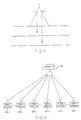
- the satellite communication system comprises a plurality of satellites and a plurality of earth stations.
- first and second satellites 20 and 21 are exemplified as first and second satellites 20 and 21.
- a plurality of movable stations 23-1 through 23-N and a single base station 24 are illustrated as the earth stations.
- the first and second satellites 20 and 21 are on the geostationary orbit.
- the first satellite 20 is displaced from the second satellite 21 on the geostationary orbit.
- the base station 24 can communicate with the movable stations 23-1 through 23-N through the first and the second satellites 20 and 21.
- a signal combination circuit 25 is supplied with a frame synchronization signal of a predetermined bit pattern and a sequence of message signals.
- the frame synchronization signal and the message signals are supplied from an external device (not shown).
- the signal combination circuit 25 positions the frame synchronization signal at the head of each frame and the message signal following the frame synchronization signal to produce a combination signal.
- the combination signal is subjected to phase shift keying (PSK) by a modulator 26 to be produced as a PSK signal.
- PSK phase shift keying
- the PSK signal is sent to a spread spectrum processing modulator 27.
- the spread spectrum processing modulator 27 carries out forward spread spectrum processing of the PSK signal by a predetermined pseudo noise code signal (PN signal) to produce a code division multiplexed (CDM) spread spectrum signal.
- PN signal pseudo noise code signal
- CDM spread spectrum signal will be called a CDM signal hereinafter.
- the CDM signal is delivered to a transmitter-receiver 28 as a transmitted CDM signal and is transmitted from the transmitter-receiver 28 through a sharp directivity antenna 29 to the first satellite 20 by the use of an up-link frequency band.
- the transmitted CDM signal is repeated by the first satellite 20 as a repeated CDM signal.
- Each of the movable stations 23-1 through 23-N receives the repeated CDM signal through a down-link frequency band as a received CDM signal.
- the frame When the CDM signal is transmitted at a transmission rate within a bandwidth of ⁇ f (Hz), the frame has a frame period 1./ ⁇ f.
- Each of the up-link frequency band and the down-link frequency band must have a bandwidth of N ⁇ f (Hz), where N represents the spectrum spread parameter as called in the art.
- the received CDM signal is received at each of the movable stations 23-1 through 23-N by a low or wide directivity antenna.
- One of the movable stations 23-1 through 23-N is assigned with a particular PN signal.
- that movable station carries out inverse spread spectrum processing of the received CDM signal to reproduce the PN signal and the PSK signal.
- the PSK signal is demodulated into a reproduced combination signal.
- the movable station under consideration derives or extracts the message signal from the combination signal.
- the movable station 23-1 carries out forward spread spectrum processing of a positioning message signal into a locating CDM signal by the particular PN signal which is synchronized with the reproduced PN signal.
- the locating CDM signal is transmitted to the first and the second satellites 20 and 21 as first and second transmission signals, respectively.
- the first transmission signal is repeated by the first satellite 20 and is received by the transmitter-receiver 28 as a first reception signal.
- the second transmission signal is received as a second reception signal by a receiver 31 through a reception antenna 30.
- First and second matched filters 32 and 33 are for carrying out inverse spread spectrum processing of the first and the second reception signals, respectively.
- each of the first and the second reception signals has frames D n-1 , D n , and D n+1 in the manner depicted along an upper line labelled (a).
- Each frame has the frame period 1/ ⁇ f.
- each of the matched filters 32 and 33 produces a sequence of pulse signals located at the heads of the respective frames.
- Each pulse signal has a time duration 1/(N ⁇ f), respectively.
- the pulse signals are delivered to a calculating unit 34.
- the calculating unit 34 Based on the pulse signal sequence supplied from the first matched filter 32, the calculating unit 34 detects a first time instant of arrival of the first reception signal from the first satellite 20. Similarly, the calculating unit 34 detects a second time instant of arrival of the second reception signal from the second satellite 21 by using the pulse signal sequence produced by the second matched filter 33. Based on the first and the second time instants, the calculating unit 34 calculates the position of the movable station 23-1 by the use of triangulation in the manner known in the art. This position data is transmitted to the movable station 23-1 through the first satellite 20 as described above.
- the locating CDM signal is transmitted by using a wide frequency bandwidth N ⁇ f of each of the first satellites 20 and 21. Therefore, it is possible to determine the position with a high degree of accuracy.
- the wide frequency band is occupied by the locating CDM signal. This makes it difficult to transmit other CDM signals through t:he frequency bandwidth and results in a reduction of efficiency of transmission.
- the frequency band is divided into a lower frequency band and a higher frequency band.
- the lower frequency, band is used in transmitting frequency division multiplexed signals. Only the higher frequency band is used in transmitting the CDM signals.
- the lower frequency band has a plurality of frequency subbands adjacent to one another.
- the frequency division multiplexed signal consists of data signals transmitted through the respective frequency subbands.
- the frequency subbands are called first frequency channels or frequency slots.
- Each spread spectrum signal is a CDM signal and carries the message signals subjected to spread spectrum processing.
- the spread spectrum signals are unavoidably received with a reduced gain.
- a satellite communication system comprises a single base station 35, first through m-th fixed stations 36-1 to 36-m, and first through k-th movable or mobile stations 37-1 to 37-k.
- Each of the movable stations 37-1 to 37-k may be carried by a vehicle, such as an automobile or an airplane.
- Each of the base station 35 and the movable stations 37 is according to a first embodiment of this invention as will become clear as the description proceeds.
- the satellite communication system may comprise a plurality of base stations which cooperate with the fixed stations.
- the illustrated base station 35, the fixed stations 36-1 to 36-m, and the movable stations 37-1 to 37-k are communicable with one another through the first and second satellites 20 and 21 which are assumed to be geostationarily located at different positions of a geostationary orbit.
- the first and the second satellites 20 and 21 may not always be geostationary satellites but orbiting satellites which run along different orbits.
- the base station 35 bidirectionally communicates with the fixed stations 36-1 to 36-m and the movable stations 37-1 to 37-k not only through the first satellite 20 but also through the second satellite 21.
- up-link and down-link frequency bands are determined between the base station 35 and the movable stations 37-1 to 37-k and between the base station 35 and the fixed stations 36-1 to 36-m and may be common to the first and the second satellites 20 and 21.
- each of the up-link and the down-link frequency bands comprises a plurality of frequency subbands or channels spaced apart from one another along a frequency axis with a frequency gap or slots interposed between the frequency subbands, as shown along a top line labelled (a).
- Each frequency subband is called a first frequency channel.
- each frequency gap is called a second frequency channel.
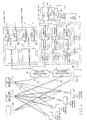
- the base station 35 comprises a frequency division multiplexing (FDM) unit 38 for carrying out frequency division multiplexing of a plurality of data signals such as sound signals to produce an FDM signal.
- FDM frequency division multiplexing
- DEMUX demultiplexing
- a demultiplexing (DEMUX) unit 39 is for demultiplexing a reception FDM signal to reproduce a plurality of data signals.
- a spread spectrum processing (SSP) unit 40 carries out forward spread spectrum processing of a message signal to produce a CDM signal.
- First and second inverse spread spectrum processing (first and second ISSP) units 41 and 42 are for carrying out inverse spread spectrum processing on first and second reception CDM signals to reproduce message signals, respectively.
- the FDM unit 38, the demultiplexing unit 39, and the first inverse spread spectrum processing unit 41 are connected to a first transmitter-receiver 43 connected to a first sharp directivity antenna 44 directed to the second satellite 21.
- the second inverse spread spectrum processing unit 42 and the spread spectrum processing unit 40 are connected to a second transmitter-receiver 45 accompanied by a second sharp directivity antenna 46 directed to the first satellite 20.
- the first movable station 37-1 comprises a data modulator 47, a demodulation (DEM) unit 48, a spread spectrum modulation (SS MOD) unit 49, and a spread spectrum demodulation (SS DEM) unit 50.
- a transmitter-receiver 51 is coupled to a low or wide directivity antenna 52 and is connected to the data modulator 47, the demodulation unit 48, the spread spectrum modulation unit 49, and the spread spectrum demodulation unit 50.
- the data modulator 47 modulates a predetermined subcarrier assigned to the movable station 37-1 by a transmitting data signal to produce a modulated signal.
- the predetermined subcarrier is one of the first frequency channels that is assigned to the first movable station 37-1.
- the data modulator 47 modulates the predetermined subcarrier by the transmitting data signal and serves as a modulating arrangement for modulating a selected one of the frequency subbands or the first frequency channels into a transmission subband signal by the transmitting data signal which serves as a first input signal.
- a message signal has a predetermined code sequence assigned to the first movable station 37-1 as a second input signal and is delivered to the spread spectrum modulation unit 49.
- the spread spectrum modulation unit 49 carries out spread spectrum processing of the message signal to produce a CDM (code division multiplexed) signal as a spread spectrum transmission signal having the up-link frequency band.
- CDM code division multiplexed
- the transmission subband signal and the CDM signal are delivered to the transmitter-receiver 51.
- the transmitter-receiver 51 transmits the transmission subband signal through the predetermined subband as a first transmission signal.
- the transmitter-receiver 51 serves as a first transmitting arrangement for transmitting the transmission subband signal.
- the transmitter-receiver 51 transmits the CDM signal through the up-link frequency band as a second transmission signal.
- the transmitter-receiver 51 serves as a second transmitting arrangement for transmitting the CDM signal.
- the first and the second transmission signals are collectively called a transmission signal hereinabove.
- the base station 35 (Fig. 4) transmits a transmission subband signal and a spread spectrum transmission signal.
- a combination of the transmission subband signal and the spread spectrum transmission signal is termed a transmitted signal when transmitted from the base station 35.
- the first movable station 37-1 receives, as a first reception signal, the transmission subband signal transmitted from the base station 35 through one of the frequency subbands that is assigned in the down-link frequency band to the movable station 37-1 as a predetermined one of the frequency subbands. Furthermore, the movable station 37-1 receives, as a second reception signal, the spread spectrum transmission signal which is transmittedd from the base station 35 through the up-link frequency band and is repeated by the first satellite 20 through the down-link frequency band. Responsive to the first and the second reception signals, the transmitter-receiver 51 produces first and second reception band signals.
- the demodulation unit 48 produces a reception subband signal from the first reception band signal and demodulates the reception subband signal into a data signal.
- the spread spectrum demodulation unit 50 produces a frequency gap signal from the second reception band signal and carries out inverse spread spectrum processing on the frequency gap signal to produce a message signal.
- the demodulation unit 48 comprises a channel selection filter 48a for selecting the reception subband signal from the first reception band signal.
- a data demodulator 48 demodulates the reception subband signal into the data signal.
- the channel selection filter 48a serves as a first receiving arrangement.
- the data demodulator 48b serves as a first producing arrangement.
- the spread spectrum demodulation unit 50 comprises a comb filter bank 50a for selecting the frequency gap signal from the second reception band signal.
- a matched filter 50b carries out inverse spread spectrum processing of the frequency gap signal to produce a frequency matched signal.
- a message demodulator 50c demodulates the frequency matched signal into the data signal.
- the comb filter bank 50a serves as a second receiving arrangement.
- the matched filter 50b and the message demodulator 50c serve as a second producing arrangement.
- the other movable stations 37-2 to 37-k are similar in structure and operation to the movable station 37-1 and will not be described any longer.
- each of the first frequency channels or the frequency subbands and the second frequency channels or the frequency gaps has a prescribed bandwidth ⁇ f.
- the first frequency channels are assigned to the fixed stations 36-1 to 36-m and the movable stations 37-1 to 37-k, respectively.
- the base station 35 communicates with the fixed stations 36-1 to 36-m and the movable stations 37-1 to 37-k by sending data signals
- the base station 35 communicates with the fixed stations 36-1 to 36-m and the movable stations 37-1 to 37-k by using the first frequency channels corresponding to the fixed stations 36-1 to 36-m and the movable stations 37-1 to 37-k, respectively.
- the FDM unit 38 comprises first through (k+m)-th data modulators 38-1 to 38-(k+m) corresponding to the fixed stations 36-1 to 36-m and the movable stations 37-1 to 37-k, respectively.
- the data modulators 38-1 to 38-(k+m) modulate subcarriers different from each other by the data signals to produce a plurality of modulated signals, respectively.
- a multiplexer 53 carries out FDM of the modulated signals to produce an FDM signal.
- the FDM signal is transmitted to the second satellite 21 through the first frequency channels of the up-link frequency band by the first transmitter-receiver 43.
- the second transmitter-receiver 45 transmits a sequence of standard bursts as a CDM signal by using the up-link frequency band to the first satellite 20.
- the standard bursts are in a predetermined period.
- a signal combination unit 54 combines a frame synchronization signal with the standard burst sequence into a sequence of message signals to produce a sequence of combined signals.
- a PSK modulator 55 modulates the combined signals according to PSK to produce a modulation signal.
- a spread spectrum modulator 56 carries out forward spread spectrum processing of the modulation signal to produce a CDM signal.
- the CDM signal is transmitted to the first satellite 20 through the up-link frequency band by the second transmitter-receiver 45.
- Each of the data modulators 38-1 to 38-(k+m) serves as the modulating arrangement for modulating a selected one of the frequency subbands into a transmission subband signal by the data signal which serves as a first input signal.
- the spread spectrum processing unit 40 carries out spread spectrum processing of the message signal sequence to produce a CDM signal as a spread spectrum signal having the up-link frequency band in the manner described above.
- the first transmitter-receiver 43 serves as the first transmitting arrangement described above, and the second transmitter-receiver 45, as a second transmission signal.
- each of the fixed stations 36-1 to 36-m comprises a data modulator, a demodulation unit, and a transmitter receiver similar in structure and operation to the modulator 47, the demodulation unit 48, and the transmitter-receiver 51 described in conjunction with Fig. 6.
- the data modulator and the demodulation unit are connected directly to the transmitter-receiver which is coupled, in turn, to an antenna directed to the second satellite 21 alone like the first sharp directivity antenna 44.
- the fixed stations 36-1 to 36-m and the movable stations 37-1 to 37-k are supplied with the FDM reception signal and CDM reception signal as first and second reception signals, respectively.
- the first reception signal has a first partial spectrum of FDM reception signal assigned to the first frequency channels.
- the second reception signal has a second partial spectrum of CDM reception signal assigned to both of the first and the second frequency channels.
- the first and the second partial spectra are collectively called a reception spectrum.
- the transmitter-receiver 51 receives the FDM reception signal and the second reception signal as first and second reception signals, respectively.
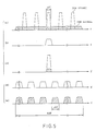
- the channel selection filter 48a has a band-pass characteristic for allowing an i-th frequency subband to pass therethrough, as shown in Fig. 5(b).
- the channel selection filter 48a supplies the demodulator 48b with a modulated signal assigned to the i-th frequency subband as shown in Fig. 5(c).
- the modulated signal is demodulated by the demodulator 48b into a data signal, such as a sound signal.
- the comb filter bank 50a has a filter characteristic, so as to allow the second frequency channels to pass therethrough as shown in Fig. 5(d). Consequently, the comb filter bank 50a separates the CDM signal from the FDM signal.
- the CDM signal is spread over a frequency bandwidth N ⁇ f and is divided into a plurality of partial spectrum signals each of which has a frequency bandwidth of ⁇ f and which is spaced apart from one another as shown in Fig. 5(e).
- the CDM signal is supplied through the matched filter 50b to the message demodulator 50c to be demodulated into a demodulated PSK signal (or a message signal) and a demodulated PN signal.
- the modulated signal is transmitted from the modulator 47 to the second satellite 21 through the first frequency channel assigned to the movable station 37-1 of the up-link frequency band as the first transmission signal.
- the reception signal from the second satellite 21 is received by the first transmitter-receiver 43 through the first antenna 44 and is supplied to a demultiplexer 57.
- the demultiplexer 57 supplies the reception signal as the modulated signal to a selected one of first through (k+m)-th data demodulators 39-1 to 39-(k+m), for example, the data demodulator 39-1.
- the data demodulator 39-1 demodulates the modulated signal to produce the data signal.
- a position signal is sent as the message signal to a PSK modulator 49a to be subjected to PSK and to be produced as a PSK signal.
- the PSK signal is supplied to a spread spectrum modulator 49b.
- the spread spectrum modulator 49b carries out forward spread spectrum processing of the PSk signal by using the own PN signal in synchronism with the demodulated PN signal to produce a CDM signal.
- the CDM signal is transmitted to the first and second satellites 20 and 21 by using the first and second frequency channels of up-link frequency bands.
- the reception CDM signals from the first and second satellites 20 and 21 are received by the first and the second transmitter-receivers 43 and 46 through the first and the second antennae 44 and 46 to be supplied to comb filter banks 41a and 42a, respectively.
- the comb filter banks 41a and 42a pass only the second frequency channels, respectively.
- the reception CDM signals are subjected to inverse spread spectrum processing by matched filters 41b and 42b and are delivered to the message demodulators 41C and 42c to be demodulated into first and second positioning message signals.
- the first and second positioning message signals are supplied to the calculation unit 58.
- the calculation unit 58 comprises a detecting circuit 58a and a calculating circuit 58b.
- the detecting circuit 58a detects a first arrival time instant and a second arrival time instant based on the first and the second positioning message signals, respectively.
- the calculating circuit 58b calculates the position of the movable station 37-1 in question by the use of triangulation with reference to the first arrival time instant and the second arrival time instant.
- the position signal is transmitted to the movable station 37-1 by using forward spread spectrum processing.
- the reception CDM signal When the reception CDM signal is assumed to be represented as S(t) in a time base, namely, as a function of time t, the reception CDM signal may be represented as S( ⁇ ) in a frequency base, namely, as a function of frequency.
- S(t) ⁇ S(t)e -j ⁇ t dt.
- each of the comb filter banks 41a and 42a have a frequency response characteristic F( ⁇ ) represented by: where ⁇ a n ⁇ is representative of a Fourier coefficient.
- each output signal ⁇ (t) from comb filter banks 41a and 42a is represented by:
- first and second terms on the righthand side represent a primary response and a subsidiary or echo response.
- the echo response accompanies forward and rearward the primary response at every time instant of n/ ⁇ f, where n represents a natural number.
- Each of the primary response and the echo response is restricted to a pulse width of 1/(N ⁇ f) in Fig. 7. This shows that the pulse width is in inverse proportion to each frequency width of the up-link frequency band and the down-link frequency band.
- each output signal from the comb filter banks 41a and 42a appears at a frequency interval of 1/ ⁇ f, due to the above-mentioned primary response and echo response. If the frequency interval ⁇ f is equal to the transmission rate R of the reception CDM signal, the echo response adversely affects the primary response among the codes of the reception CDM signal. As a result, interference takes place among the codes of reception CDM signal.
- the transmission rate R may be selected so as to become larger than the bandwidth ⁇ f of the second frequency channel as understood by Equation (5).
- the transmission rate R may be selected so as to become larger than the bandwidth ⁇ f of the second frequency channel as understood by Equation (6).
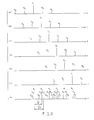
- the reception CDM signal is produced in the form of a sequence of codes depicted at a1 to a5 through e1 to e4 along first through fifth lines of Fig. 8, respectively, and may be made to correspond to the output signal of the comb filter bank.
- the comb filter bank produces, as the output signal, a primary pulse a1 resulting from the primary response.
- the remaining pulses a2 through a5 are produced from the echo response.
- primary pulses b1 through e1 appear as a result of the primary response while the remaining pulses b2 to b5; c2 to c5; d2 to d5; and e2 to e4 appear as results of the echo response.
- the primary pulse a1 and the echo pulses a2 through a5 are arranged at the interval of 1/ ⁇ f one another.
- the primary pulses b1 to e1 and the echo pulses b2 to b5 through e2 to e4 are arranged at the interval 1/ ⁇ f, respectively.
- the matched filter produces a code sequence arranged as shown along a bottom line of Fig. 8(f).
- the reception CDM signal is produced in the form of a sequence of codes a1 to a5 through f1 to f4 when the transmission rate R is greater than the frequency bandwidth ⁇ f.
- the matched filter produces an output signal as shown in Fig. 9(g).
- the primary pulses and the echo pulses can be separated from each other and interference is therefore avoidable due to the primary and the echo responses.
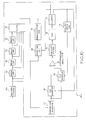
- the matched filter 41b supplies a delay circuit 61 and an adder 65 with an output signal as shown along the bottom line of Fig. 8.
- the delay circuit 61 produces a first delay signal delayed by a delay time 1/ ⁇ f relative to the output signal.
- the first delay signal is successively delayed by delay circuits 62 to 64 and thereafter sent to the adder 65.
- the delay circuits 62 to 64 produce second through fourth delay signals delayed by two, three, and four times the delay time 1/ ⁇ f relative to the output signal, respectively.
- the adder 65 adds the output signal to the first through the fourth delay signals to produce a sum signal.
- the echo pulses a2 through a5 are added to the primary pulse a1.
- the echo pulses b2 through b5, c2 through c5, d2 through d5, and e2 through e5 are added to the primary response pulses b1, c1, d1, and e1, respectively.
- the sum signal is supplied to a sampling circuit 66 and a square-law detector 56.
- the square-law detector 67 calculates a square of the sum signal to produce a square signal and supplies the square signal to first and second samplers 68 and 69.
- the samplers 68 and 69 send first and second sampled signals to a differential amplifier 70 to produce an amplified signal.
- the amplified signal is supplied to a voltage-controlled oscillator (VCO) 72 through a low-pass filter 71.
- VCO 72 delivers a controlled signal to a counter 73 and a digital delay circuit 74.
- the counter 73 outputs a clock signal based on the output signal from the VCO 72.
- the clock signal is supplied to the digital delay circuit 74 and the sampler 66.
- the digital delay circuit 74 delays the clock signal with reference to the controlled signal given from the VCO 72 to produce a delayed clock signal delayed to the clock signal.
- the clock signal and the delayed clock signal are supplied to the samplers 68 and 69, respectively, so that the samplers 68 and 69 sample the detected signal at sampling points Z1 and Z2 to produce a first sampled signal and a second sampled signal, respectively.
- the output signal from the differential amplifier 70 becomes zero.
- the counter 73 generates a third clock signal in the point corresponding to a sampling point Z3.
- the third clock signal is supplied to the sampling circuit 66 so that the sampling circuit 66 samples the sum signal at the peak level of the sum signal to produce a third sampled signal.
- the third sampled signal is supplied to a demodulation circuit 75.
- the demodulation circuit 75 demodulates the third sampled signal to reproduce the message signal.
- the message signal is supplied to the calculation unit 58.
- the message demodulator 49c is similar in structure and operation to the message demodulator 48c.
- Each of the message demodulators in the movable stations is similar in structure and operation to the message demodulator in the base station.
- the message demodulator may have a plurality of delay circuits.
- the message demodulator has the delay circuits 61 and 62.
- the adder 65 adds the output signal from the matched filter, the first delay signal, and the second delay signal to produce a sum signal.
- a satellite 100 may be used together with the satellites 20 and 21.
- the base station 35 may further comprise a third inverse spread spectrum processing (third ISSP) unit 101.
- the third inverse spread spectrum processing unit 101 comprises a comb filter bank 101a, a matched filter 101b, and a message demodulator 101c.
- a receiver 102 is connected to the comb filter bank 101a and has a third sharp directivity antenna 102a directed to the satellite 100.
- the message demodulator 101c is connected to the calculation unit 58 as shown in broken lines in Fig. 4.
- the movable station can transmit a position message signal to the satellites 20, 21, and 100 without receiving the time standard signal.
- the calculation unit 58 detects a third arrival time instant of the reception signal from the satellite 100 in response to the positioning message signal given from the message demodulator 101c.
- the calculation unit 58 calculates the position of the movable station based on the first, second, and third arrival time instants.
- a satellite communication system comprises first through m-th fixed stations 200-1 to 200-m, first through k-th fixed stations 300-1 to 300-k, and first through n-th fixed stations 400-1 to 400-n, in addition to a satellite 500.
- Each of the fixed stations 200-1 to 200-m comprises an FDM unit and a demultiplexing unit which are similar in structure and operation to those of the base station 35 shown in Fig. 5.
- the FDM unit and the demultiplexing unit are connected to a transmitter-receiver (not shown) having a sharp directivity antenna directed to the satellite 500.
- Each of the fixed stations 300-1 to 300-k comprises a spread spectrum processing unit and an inverse spread spectrum processing unit, like the base station 35 shown in Fig. 4.
- the spread spectrum processing unit and the inverse spread spectrum processing unit are connected to a transmitter-receiver having a sharp directivity antenna directed to the satellite 500.
- Each of the fixed stations 400-1 to 400-n comprises an FDM unit, a demultiplexing unit, a spread spectrum processing unit, and an inverse spread spectrum processing unit and may be similar in structure and operation to those of the base station 35 shown in Fig. 5.
- a transmitter-receiver is connected to the FDM unit, the demultiplexing unit, the spread spectrum processing unit, and the inverse spread spectrum processing unit and has a sharp directivity antenna directed to the satellite 300.
- the fixed stations 200-1 to 200-m bidirectionally communicate with the fixed stations 400-1 to 400-n by sending FDM signals, respectively.
- the fixed stations 300-1 to 300-k bidirectionally communicate with the fixed stations 400-1 to 400-n by sending CDM signals, respectively.
Landscapes
- Engineering & Computer Science (AREA)
- Computer Networks & Wireless Communication (AREA)
- Signal Processing (AREA)
- Radio Relay Systems (AREA)
Applications Claiming Priority (4)
| Application Number | Priority Date | Filing Date | Title |
|---|---|---|---|
| JP209764/87 | 1987-08-24 | ||
| JP62209764A JPS6451837A (en) | 1987-08-24 | 1987-08-24 | Small sized earth station |
| JP221587/87 | 1987-09-04 | ||
| JP62221587A JPS6465473A (en) | 1987-09-04 | 1987-09-04 | Satellite communication and position measurement system for moving body |
Publications (2)
| Publication Number | Publication Date |
|---|---|
| EP0304890A2 true EP0304890A2 (de) | 1989-03-01 |
| EP0304890A3 EP0304890A3 (de) | 1990-10-10 |
Family
ID=26517640
Family Applications (1)
| Application Number | Title | Priority Date | Filing Date |
|---|---|---|---|
| EP19880113790 Ceased EP0304890A3 (de) | 1987-08-24 | 1988-08-24 | Erdstation für die wirkungsvolle Nutzung des Frequenzbandes eines Satelliten |
Country Status (4)
| Country | Link |
|---|---|
| US (1) | US4905221A (de) |
| EP (1) | EP0304890A3 (de) |
| AU (1) | AU605447B2 (de) |
| CA (1) | CA1293999C (de) |
Cited By (3)
| Publication number | Priority date | Publication date | Assignee | Title |
|---|---|---|---|---|
| EP0574282A1 (de) * | 1992-06-10 | 1993-12-15 | SOCIETE d'ETUDES de TELE-INFORMATIQUES et COMMUNICATIONS SYSTEME DITE SETICS: Société Anonyme : | Einrichtung zur Kodierung und Dekodierung zur Übertragung in Frequenzteilbändern |
| CN107797098A (zh) * | 2017-09-07 | 2018-03-13 | 西安空间无线电技术研究所 | 一种基于测控数传一体化的距离零值校准方法和系统 |
| CN109581436A (zh) * | 2017-09-28 | 2019-04-05 | 清华大学 | 相邻频点导航信号联合接收机和接收方法 |
Families Citing this family (65)
| Publication number | Priority date | Publication date | Assignee | Title |
|---|---|---|---|---|
| US5113443A (en) * | 1987-07-17 | 1992-05-12 | Brockman Milton H | Method for scrambling satellite communications |
| US5499265A (en) * | 1989-08-07 | 1996-03-12 | Omnipoint Data Company, Incorporated | Spread spectrum correlator |
| US5016255A (en) * | 1989-08-07 | 1991-05-14 | Omnipoint Data Company, Incorporated | Asymmetric spread spectrum correlator |
| US4942589A (en) * | 1989-10-04 | 1990-07-17 | Unisys Corporation | Channelized binary-level hop rate detector |
| US4985899A (en) * | 1989-10-05 | 1991-01-15 | The Boeing Company | Intercept detector for spread-spectrum signals |
| US5113409A (en) * | 1989-10-17 | 1992-05-12 | Stewart Clarence H | Spread spectrum intercept apparatus and method |
| US5016256A (en) * | 1989-10-17 | 1991-05-14 | Stewart Clarence H | Spread spectrum intercept apparatus and method |
| US5103460A (en) * | 1989-10-17 | 1992-04-07 | Clarence H. Stewart | Spread spectrum intercept apparatus and method |
| US5265121A (en) * | 1989-10-17 | 1993-11-23 | Juanita H. Stewart | Spread spectrum coherent processor |
| CH679718A5 (de) * | 1989-10-19 | 1992-03-31 | Ascom Zelcom Ag | |
| WO1992002094A1 (en) * | 1990-07-23 | 1992-02-06 | Omnipoint Corporation | Sawc phase-detection method and apparatus |
| CA2094710C (en) * | 1990-10-23 | 1998-12-01 | Robert Clyde Dixon | Method and apparatus for establishing spread spectrum communications |
| US7020125B2 (en) * | 1990-12-05 | 2006-03-28 | Interdigital Technology Corporation | Broadband CDMA overlay system and method |
| US5506864A (en) * | 1990-12-05 | 1996-04-09 | Interdigital Technology Corporation | CDMA communications and geolocation system and method |
| US5351269A (en) * | 1990-12-05 | 1994-09-27 | Scs Mobilecom, Inc. | Overlaying spread spectrum CDMA personal communications system |
| US5402413A (en) * | 1991-04-08 | 1995-03-28 | Omnipoint Corporation | Three-cell wireless communication system |
| US5694414A (en) * | 1991-05-13 | 1997-12-02 | Omnipoint Corporation | Multi-band, multi-mode spread-spectrum communication system |
| US5887020A (en) * | 1991-05-13 | 1999-03-23 | Omnipoint Corporation | Multi-band, multi-mode spread-spectrum communication system |
| US5790587A (en) * | 1991-05-13 | 1998-08-04 | Omnipoint Corporation | Multi-band, multi-mode spread-spectrum communication system |
| US5815525A (en) * | 1991-05-13 | 1998-09-29 | Omnipoint Corporation | Multi-band, multi-mode spread-spectrum communication system |
| CA2102914A1 (en) * | 1991-05-13 | 1992-11-26 | Robert C. Dixon | Dual mode transmitter and receiver |
| US5796772A (en) * | 1991-05-13 | 1998-08-18 | Omnipoint Corporation | Multi-band, multi-mode spread-spectrum communication system |
| US5285469A (en) * | 1991-06-03 | 1994-02-08 | Omnipoint Data Corporation | Spread spectrum wireless telephone system |
| US5258995A (en) * | 1991-11-08 | 1993-11-02 | Teknekron Communications Systems, Inc. | Wireless communication system |
| WO1993009493A1 (en) * | 1991-11-08 | 1993-05-13 | Teknekron Communications Systems, Inc. | A wireless communication system |
| JP2554219B2 (ja) * | 1991-11-26 | 1996-11-13 | 日本電信電話株式会社 | ディジタル信号の重畳伝送方式 |
| JP3766434B2 (ja) * | 1991-12-16 | 2006-04-12 | ザーカム ワイヤレス, インコーポレイテッド | スペクトル拡散データ送信システム |
| US5295138A (en) * | 1992-04-21 | 1994-03-15 | Northwest Starscon Limited Partnership | Apparatus and method for optimal frequency planning in frequency division multiplexing transmissions |
| GB9209027D0 (en) * | 1992-04-25 | 1992-06-17 | British Aerospace | Multi purpose digital signal regenerative processing apparatus |
| US5233626A (en) * | 1992-05-11 | 1993-08-03 | Space Systems/Loral Inc. | Repeater diversity spread spectrum communication system |
| US5461629A (en) * | 1992-09-09 | 1995-10-24 | Echelon Corporation | Error correction in a spread spectrum transceiver |
| US5355389A (en) * | 1993-01-13 | 1994-10-11 | Omnipoint Corporation | Reciprocal mode saw correlator method and apparatus |
| SE518014C2 (sv) * | 1993-06-25 | 2002-08-13 | Motorola Inc | Mobilsystem och metod för användning och överlämning mellan smalbandig och bredbandig kommunikation |
| US5363402A (en) * | 1993-09-08 | 1994-11-08 | Rockwell International Corp. | HF radio apparatus operable in multiple communication modes |
| US6088590A (en) * | 1993-11-01 | 2000-07-11 | Omnipoint Corporation | Method and system for mobile controlled handoff and link maintenance in spread spectrum communication |
| US6005856A (en) * | 1993-11-01 | 1999-12-21 | Omnipoint Corporation | Communication protocol for spread spectrum wireless communication system |
| IL111469A0 (en) * | 1993-11-01 | 1994-12-29 | Omnipoint Corp | Despreading/demodulating direct sequence spread spectrum signals |
| US6094575A (en) * | 1993-11-01 | 2000-07-25 | Omnipoint Corporation | Communication system and method |
| US5475707A (en) * | 1994-02-28 | 1995-12-12 | Westinghouse Norden Systems | Broadband communications system |
| US5859874A (en) * | 1994-05-09 | 1999-01-12 | Globalstar L.P. | Multipath communication system optimizer |
| US5745084A (en) * | 1994-06-17 | 1998-04-28 | Lusignan; Bruce B. | Very small aperture terminal & antenna for use therein |
| US5649318A (en) * | 1995-03-24 | 1997-07-15 | Terrastar, Inc. | Apparatus for converting an analog c-band broadcast receiver into a system for simultaneously receiving analog and digital c-band broadcast television signals |
| TW274170B (en) * | 1994-06-17 | 1996-04-11 | Terrastar Inc | Satellite communication system, receiving antenna & components for use therein |
| US5742583A (en) | 1994-11-03 | 1998-04-21 | Omnipoint Corporation | Antenna diversity techniques |
| US5784403A (en) * | 1995-02-03 | 1998-07-21 | Omnipoint Corporation | Spread spectrum correlation using saw device |
| US5745484A (en) * | 1995-06-05 | 1998-04-28 | Omnipoint Corporation | Efficient communication system using time division multiplexing and timing adjustment control |
| US5689502A (en) * | 1995-06-05 | 1997-11-18 | Omnipoint Corporation | Efficient frequency division duplex communication system with interleaved format and timing adjustment control |
| US5802046A (en) * | 1995-06-05 | 1998-09-01 | Omnipoint Corporation | Efficient time division duplex communication system with interleaved format and timing adjustment control |
| US5959980A (en) * | 1995-06-05 | 1999-09-28 | Omnipoint Corporation | Timing adjustment control for efficient time division duplex communication |
| JP2000502222A (ja) * | 1995-12-07 | 2000-02-22 | ビスター・テレコミュニケーションズ・インコーポレイテッド | 無線パケットデータ分配通信システム |
| US5991279A (en) * | 1995-12-07 | 1999-11-23 | Vistar Telecommunications Inc. | Wireless packet data distributed communications system |
| US7590083B2 (en) * | 1995-12-07 | 2009-09-15 | Transcore Link Logistics Corp. | Wireless packet data distributed communications system |
| US5923648A (en) * | 1996-09-30 | 1999-07-13 | Amsc Subsidiary Corporation | Methods of dynamically switching return channel transmissions of time-division multiple-access (TDMA) communication systems between signalling burst transmissions and message transmissions |
| JP3323760B2 (ja) * | 1996-11-07 | 2002-09-09 | 株式会社日立製作所 | スペクトラム拡散通信システム |
| US5995495A (en) * | 1997-05-23 | 1999-11-30 | Mci Communications Corporation | Method of and system for providing geographically targeted broadcast satellite service |
| US6052364A (en) * | 1997-06-13 | 2000-04-18 | Comsat Corporation | CDMA system architecture for satcom terminals |
| US6625204B1 (en) | 1998-04-24 | 2003-09-23 | Aloha Networks, Inc. | Synchronization and bit detection in a single spreading sequence SAMA receiver |
| US6661996B1 (en) | 1998-07-14 | 2003-12-09 | Globalstar L.P. | Satellite communication system providing multi-gateway diversity to a mobile user terminal |
| US6947469B2 (en) | 1999-05-07 | 2005-09-20 | Intel Corporation | Method and Apparatus for wireless spread spectrum communication with preamble processing period |
| US6198989B1 (en) * | 1999-05-21 | 2001-03-06 | Trimble Navigation Ltd | Monitor and remote control via long baseline RTK |
| EP1316233B1 (de) | 2000-08-02 | 2011-10-05 | ATC Technologies, LLC | Koordinierte Wiederverwendung von Frequenzen von einem irdischen System und einem Satellitensystem. |
| US6859652B2 (en) | 2000-08-02 | 2005-02-22 | Mobile Satellite Ventures, Lp | Integrated or autonomous system and method of satellite-terrestrial frequency reuse using signal attenuation and/or blockage, dynamic assignment of frequencies and/or hysteresis |
| US7792488B2 (en) | 2000-12-04 | 2010-09-07 | Atc Technologies, Llc | Systems and methods for transmitting electromagnetic energy over a wireless channel having sufficiently weak measured signal strength |
| KR101154992B1 (ko) | 2006-04-24 | 2012-06-14 | 엘지전자 주식회사 | 다중 사용자 시스템에 적용되는 신호 수신 방법 |
| US8217760B2 (en) * | 2008-03-20 | 2012-07-10 | Checkpoint Systems, Inc. | Applique nodes for performance and functionality enhancement in radio frequency identification systems |
Citations (2)
| Publication number | Priority date | Publication date | Assignee | Title |
|---|---|---|---|---|
| US4359733A (en) | 1980-09-23 | 1982-11-16 | Neill Gerard K O | Satellite-based vehicle position determining system |
| US4455651A (en) | 1980-10-20 | 1984-06-19 | Equatorial Communications Company | Satellite communications system and apparatus |
Family Cites Families (5)
| Publication number | Priority date | Publication date | Assignee | Title |
|---|---|---|---|---|
| US4425642A (en) * | 1982-01-08 | 1984-01-10 | Applied Spectrum Technologies, Inc. | Simultaneous transmission of two information signals within a band-limited communications channel |
| US4672605A (en) * | 1984-03-20 | 1987-06-09 | Applied Spectrum Technologies, Inc. | Data and voice communications system |
| EP0208425A3 (de) * | 1985-06-13 | 1988-01-13 | Devon County Council | Übertragung per Fernsehsignalnebenträger |
| US4703474A (en) * | 1986-02-28 | 1987-10-27 | American Telephone And Telegraph Company, At&T Bell Laboratories | Spread spectrum code-division-multiple-access (SS-CDMA) lightwave communication system |
| US4811357A (en) * | 1988-01-04 | 1989-03-07 | Paradyne Corporation | Secondary channel for digital modems using spread spectrum subliminal induced modulation |
-
1988
- 1988-08-23 CA CA000575448A patent/CA1293999C/en not_active Expired - Lifetime
- 1988-08-24 AU AU21504/88A patent/AU605447B2/en not_active Ceased
- 1988-08-24 EP EP19880113790 patent/EP0304890A3/de not_active Ceased
- 1988-08-24 US US07/236,019 patent/US4905221A/en not_active Expired - Fee Related
Patent Citations (2)
| Publication number | Priority date | Publication date | Assignee | Title |
|---|---|---|---|---|
| US4359733A (en) | 1980-09-23 | 1982-11-16 | Neill Gerard K O | Satellite-based vehicle position determining system |
| US4455651A (en) | 1980-10-20 | 1984-06-19 | Equatorial Communications Company | Satellite communications system and apparatus |
Non-Patent Citations (1)
| Title |
|---|
| R.C. DIXON: "a book "Spread Spectrum Systems"", 1976, WILEY & SONS, INC |
Cited By (5)
| Publication number | Priority date | Publication date | Assignee | Title |
|---|---|---|---|---|
| EP0574282A1 (de) * | 1992-06-10 | 1993-12-15 | SOCIETE d'ETUDES de TELE-INFORMATIQUES et COMMUNICATIONS SYSTEME DITE SETICS: Société Anonyme : | Einrichtung zur Kodierung und Dekodierung zur Übertragung in Frequenzteilbändern |
| FR2692421A1 (fr) * | 1992-06-10 | 1993-12-17 | Setics | Dispositifs de codage et décodage pour transmission en sous-bandes de fréquence. |
| CN107797098A (zh) * | 2017-09-07 | 2018-03-13 | 西安空间无线电技术研究所 | 一种基于测控数传一体化的距离零值校准方法和系统 |
| CN107797098B (zh) * | 2017-09-07 | 2020-03-24 | 西安空间无线电技术研究所 | 一种基于测控数传一体化的距离零值校准方法和系统 |
| CN109581436A (zh) * | 2017-09-28 | 2019-04-05 | 清华大学 | 相邻频点导航信号联合接收机和接收方法 |
Also Published As
| Publication number | Publication date |
|---|---|
| CA1293999C (en) | 1992-01-07 |
| EP0304890A3 (de) | 1990-10-10 |
| AU2150488A (en) | 1989-03-02 |
| US4905221A (en) | 1990-02-27 |
| AU605447B2 (en) | 1991-01-10 |
Similar Documents
| Publication | Publication Date | Title |
|---|---|---|
| EP0304890A2 (de) | Erdstation für die wirkungsvolle Nutzung des Frequenzbandes eines Satelliten | |
| CA1285338C (en) | Satellite-based vehicle communication/position determination system | |
| EP0306918B1 (de) | Bewegliches Satellitenkommunikationssystem | |
| US5233626A (en) | Repeater diversity spread spectrum communication system | |
| EP0828352B1 (de) | Satellitensystem und Verfahren zur Überwachung des Leistungspegels unter Anwendung von digitaler Signalverarbeitung | |
| US5592471A (en) | Mobile radio receivers using time diversity to avoid service outages in multichannel broadcast transmission systems | |
| US5572516A (en) | Mobile unit communication system | |
| US5345245A (en) | Differential data signal transmission technique | |
| EP0351008B1 (de) | Übertragungssystem zur gleichzeitigen Übertragung von zwei Signalen über den gleichen Kommunikationskanal | |
| US4456988A (en) | Satellite repeater | |
| EP0751632A1 (de) | Mehrstation-kommunikationsverfahren für satellitenanordnung mit umlaufbahnen auf niedriger höhe und vorrichtung dafür | |
| EP0732814A2 (de) | Bidirektionale Satellitenkommunikationsanordnung mit Teilung eines gemeinsamen Frequenzbereichs durch Überlagerung der Signalfrequenzen | |
| WO1999037033A1 (en) | Self-interference cancellation for relayed communication networks | |
| EP2256946A3 (de) | Signal-Multiplex-Verfahren und entsprechen Sende/Empfängs-Einrichtungen | |
| EP1205040B1 (de) | Verfahren zu weitreichendem funkruf | |
| US9059780B1 (en) | Device and method for nodal multiple access into communications channels | |
| US5497402A (en) | Automatic frequency control device for satellite communications ground system | |
| US6064645A (en) | Bulk filtering and demodulation of independent FDMA sources | |
| JPH0554747B2 (de) | ||
| CA2056606A1 (en) | Communication system and demodulator used in communication system | |
| JPH0565114B2 (de) | ||
| JP2855951B2 (ja) | 小口径アンテナ用伝送方式 | |
| JPH02280423A (ja) | 重畳変調を用いた送信電力制御方式 | |
| Zhang | A master-slave synchronization method for a SAW-based on-board processing satellite system. | |
| JPH0746216A (ja) | データ伝送方法 |
Legal Events
| Date | Code | Title | Description |
|---|---|---|---|
| PUAI | Public reference made under article 153(3) epc to a published international application that has entered the european phase |
Free format text: ORIGINAL CODE: 0009012 |
|
| 17P | Request for examination filed |
Effective date: 19880825 |
|
| AK | Designated contracting states |
Kind code of ref document: A2 Designated state(s): DE FR GB |
|
| PUAL | Search report despatched |
Free format text: ORIGINAL CODE: 0009013 |
|
| AK | Designated contracting states |
Kind code of ref document: A3 Designated state(s): DE FR GB |
|
| 17Q | First examination report despatched |
Effective date: 19920928 |
|
| GRAG | Despatch of communication of intention to grant |
Free format text: ORIGINAL CODE: EPIDOS AGRA |
|
| STAA | Information on the status of an ep patent application or granted ep patent |
Free format text: STATUS: THE APPLICATION HAS BEEN REFUSED |
|
| 18R | Application refused |
Effective date: 19961003 |