EP0304903A1 - Tondeuse à gazon commandée manuellement, réglable en hauteur - Google Patents
Tondeuse à gazon commandée manuellement, réglable en hauteur Download PDFInfo
- Publication number
- EP0304903A1 EP0304903A1 EP19880113821 EP88113821A EP0304903A1 EP 0304903 A1 EP0304903 A1 EP 0304903A1 EP 19880113821 EP19880113821 EP 19880113821 EP 88113821 A EP88113821 A EP 88113821A EP 0304903 A1 EP0304903 A1 EP 0304903A1
- Authority
- EP
- European Patent Office
- Prior art keywords
- housing
- pendulum
- lawn mower
- impellers
- axle
- Prior art date
- Legal status (The legal status is an assumption and is not a legal conclusion. Google has not performed a legal analysis and makes no representation as to the accuracy of the status listed.)
- Granted
Links
- 238000000034 method Methods 0.000 claims description 10
- 238000006243 chemical reaction Methods 0.000 description 6
- 238000009420 retrofitting Methods 0.000 description 2
- 238000010276 construction Methods 0.000 description 1
- 230000007423 decrease Effects 0.000 description 1
- 238000009434 installation Methods 0.000 description 1
Images

Classifications
-
- A—HUMAN NECESSITIES
- A01—AGRICULTURE; FORESTRY; ANIMAL HUSBANDRY; HUNTING; TRAPPING; FISHING
- A01D—HARVESTING; MOWING
- A01D34/00—Mowers; Mowing apparatus of harvesters
- A01D34/01—Mowers; Mowing apparatus of harvesters characterised by features relating to the type of cutting apparatus
- A01D34/412—Mowers; Mowing apparatus of harvesters characterised by features relating to the type of cutting apparatus having rotating cutters
- A01D34/63—Mowers; Mowing apparatus of harvesters characterised by features relating to the type of cutting apparatus having rotating cutters having cutters rotating about a vertical axis
- A01D34/74—Cutting-height adjustment
-
- A—HUMAN NECESSITIES
- A01—AGRICULTURE; FORESTRY; ANIMAL HUSBANDRY; HUNTING; TRAPPING; FISHING
- A01D—HARVESTING; MOWING
- A01D2101/00—Lawn-mowers
Definitions
- the invention relates to a height-adjustable hand lawn mower with a housing on which at least two axes are provided for at least one front and at least one rear impeller which is not pivoted.
- Manual lawnmowers are generally understood to mean non-powered lawnmowers that are pushed by an operator. Such lawn mowers are usually equipped with two front and two rear swivel-mounted impellers (US-A-4 224 785).
- pendulum wheels which are understood to be wheels that can freely oscillate about an axis perpendicular to the wheel axis (US Pat. No. 2,308,076).
- the object to be achieved with the invention is seen in designing height-adjustable hand lawn mowers both for use with non-pivoting impellers and for use with pendulum wheels.
- This object has been achieved according to the invention in that the wheel or wheels provided on the front or rear of the housing are interchangeable with a pendulum wheel set, which has an axis receiving opening and can be connected to the housing.
- a pendulum wheel set ensures that the vertical axis of the pendulum wheel always remains substantially perpendicular to the ground surface when the height of both the front and rear wheels is adjusted, so that the pendulum wheels do not tilt and do not lose their functionality.
- a hand can be converted lawnmowers can be converted back to a mower with non-swiveling wheels.
- Each pendulum wheel set can expediently be connected to the housing via a connecting part, a holding rod being able to be provided between two pendulum wheel sets in order to give the hand lawn mower the required stability.
- each pendulum wheel set can have an at least partially elongated frame part which receives a holder for a pendulum wheel that can be rotated freely about a vertical axis.
- Each frame part according to the invention is advantageously provided with the opening receiving an axle, the connecting part engaging at its end remote from the pendulum wheel.
- each frame part can have an opening for receiving the support rod.
- each connecting part is provided at its end remote from the frame part with a U-shaped slot open at one end for receiving a wheel axle, the wheel axle receiving the slot having a Groove can be provided so that a secure hold of the frame part is guaranteed on the wheel axle.
- the following steps are carried out for a lawn mower with two rear and two swivel-mounted impellers on the front for carrying out the conversion process beat.
- the impellers provided on the front or rear of the housing are removed, the other two non-pivoting impellers remaining on the housing.
- a pendulum gear set is connected to one side of the housing and then a second pendulum gear set to the other side of the housing.
- the axle, from which the non-swiveling impellers have been removed is inserted into the openings on the two pendulum wheel sets. If necessary, the two pendulum wheel sets can then be connected via the support rod.
- This whole process can be carried out in a very short time, and a particularly quick connection of the pendulum wheel sets to the housing can be achieved if the rear ends of the connecting parts connected to the pendulum wheel sets are merely pushed onto the axle with the non-pivotably mounted impellers.
- a particularly secure fit is achieved if a groove has been screwed into both ends of the axle with the non-pivoting wheels.
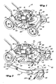
- a representative hand lawn mower 10 is shown with non-pivoting wheels 24 and 28, which has a housing 12 for a rotating knife and an upper part 14, on which a motor 16 is arranged with a vertical shaft, which receives the mower knife 18.
- the conventional housing 12 has an apron 20 which covers the path of movement of the mowing knife 18 and which is provided with a lower edge 22 which lies below the path of movement of the knife.
- the housing 12 itself, as can be seen from FIG. 1, is arranged on two rear, non-pivotably mounted impellers 24, which can be adjusted by means of an adjusting device 26, and on two front, non-pivotably arranged impellers 28, which can be adjusted in height via an adjusting device 30. Both adjusting devices are of a conventional type and a detailed description does not appear to be necessary.
- a rod-shaped axis 32 with a central U-shaped part 34 which has a right leg 36, which is connected to the other end of a transverse fastening part, is for fastening the non-pivoting front wheels 28 and for vertical adjustment is connected, which in turn connects to the outer end of a crank part 40, provided.
- the crank part 40 has an outwardly bent end part 42 on which the right front impeller is rotatably mounted.
- the U-part 34 has a left Leg 44, which is connected to the rear end of a transverse fastening part 46, the outer end of which is in turn connected to a crank part 47.
- the crank part 47 also has an outwardly bent end part 48 (FIGS. 3 and 4) on which the left front impeller is rotatably arranged.
- the fastening parts 38 and 46 of the axis 32 are aligned axially to one another and pivotally connected to the housing via right and left tabs, not shown in the drawing.
- the adjusting device 30 has a vertical, segment-like projection 54, which belongs to the left front of the housing 12, and a multiplicity of spaced-apart raster grooves 56, which are arranged in an arc shape on the outer surface.
- a lever 58 which is preferably resilient and which receives a pin 60 which can engage in one of the locking grooves 56 and thus the axis 32, engages the axis 32 can determine in different angular positions. In this way, the wheels 28 can be adjusted in various vertical positions with respect to the housing.
- Such an adjustment of the front wheels 28 is of course not carried out without an adjustment of the rear wheels so that the cutting height of the mowing knife 18 can be set correctly.
- the mowing knife 18 will assume its highest cutting height when the lever 58 assumes the position marked with A.
- the cutting height of the mowing knife decreases when the lever is pivoted clockwise into another end position, which is labeled F.
- the U-part 34 of the axis 32 also serves as a safety bracket, which prevents an operator's foot from coming too close to the front end of the housing and thus possibly coming into contact with the mowing knife. Details of such a construction can be seen in document US-A-4,224,785.
- the invention is shown on a hand lawn mower that has the front axis described above.
- the invention can also be applied to other hand lawn mowers, whereby a height adjustment is not absolutely necessary and it is also quite conceivable that the lawn mower is supported only on three wheels, for example one front and two rear.
- the maneuverability of such a hand lawnmower which has four non-pivoting wheels, is of course not great, and better maneuverability is achieved via the retrofitting according to the invention, so that curves of 180 ° can be easily negotiated without the operator needing both hands and in addition the turf is not injured by the unmovable wheels.
- the retrofitting according to the invention also makes it possible that the cutting height is not changed and that a height adjustment, provided that it is provided on the hand lawn mower, can still be carried out.
- the invention provides for this a conversion kit 80, by which the two front impellers 28 are mounted so that they cannot be pivoted.
- the conversion kit 80 consists in detail of two pendulum gear sets 82 and 84 with pendulum gears 86 and 88, which are mounted in brackets 90 and 92, which in turn can be pivoted about vertical axes in frame parts 94 and 96.
- Each frame part 94, 96 is provided with an opening 100 in which components to be described later can be accommodated.
- Each pendulum wheel set 82 and 84 is provided with connecting parts 106 and 108 which extend substantially in the longitudinal direction, these connecting parts 106 and 108 extending approximately over the entire length of the manual lawnmower 10 between the frame parts 94 and 96 to which they are connected , and the corresponding ends of a rear Extend axis 110.
- Open, U-shaped slots 114 are provided at the ends 112 of the connecting parts 106 and 108.
- Each connecting part 106 and 108 is designed so that it can follow the contour of the housing 12.
- the vertical axes 83 and 85 of the two pendulum wheels 86 and 88 always remain perpendicular to the bottom surface 111 whenever the cutting height is changed and the two front and rear wheels with reference to the housing can be adjusted.
- a holding rod 116 can also be provided for the connection between the two pendulum gear sets 82 and 84, as a result of which the conversion kit obtains its required stability during installation and, moreover, a constant distance between the frame parts 94 and 96 is maintained.
- the method for converting a conventional hand lawn mower 10 with non-pivoting front wheels 28 into one with pendulum wheels according to the invention generally requires only a few minutes, for example two.
- the rear axle 110 is modified somewhat in order to be able to accommodate the U-shaped slots 114 in the connecting parts 106 and 108. This can be done in a simple manner by reducing the diameter of the ends of the rear axle so that they correspond approximately to the height of the slot 114.
- the frame members 94 and 96 are connected to the front axle 32 by inserting the end pieces 42 and 48 into the openings 100.
- the frame part on one side is connected to the corresponding opposite parts and subsequently the frame part on the other side. If the support rod 116 is still considered necessary, it must also be used.
- the holding rod and the end parts of the front axle 32 are secured by means of corresponding nuts 126.
- Appropriate openings 102 are provided for receiving the holding rod 116 in the frame parts 94 and 96.
Landscapes
- Life Sciences & Earth Sciences (AREA)
- Environmental Sciences (AREA)
- Harvester Elements (AREA)
Applications Claiming Priority (2)
| Application Number | Priority Date | Filing Date | Title |
|---|---|---|---|
| US9064887A | 1987-08-28 | 1987-08-28 | |
| US90648 | 1998-06-04 |
Publications (2)
| Publication Number | Publication Date |
|---|---|
| EP0304903A1 true EP0304903A1 (fr) | 1989-03-01 |
| EP0304903B1 EP0304903B1 (fr) | 1991-10-30 |
Family
ID=22223677
Family Applications (1)
| Application Number | Title | Priority Date | Filing Date |
|---|---|---|---|
| EP19880113821 Expired - Lifetime EP0304903B1 (fr) | 1987-08-28 | 1988-08-25 | Tondeuse à gazon commandée manuellement, réglable en hauteur |
Country Status (3)
| Country | Link |
|---|---|
| EP (1) | EP0304903B1 (fr) |
| CA (1) | CA1303364C (fr) |
| DE (1) | DE3865926D1 (fr) |
Cited By (9)
| Publication number | Priority date | Publication date | Assignee | Title |
|---|---|---|---|---|
| EP0367891A1 (fr) * | 1988-11-07 | 1990-05-16 | Deere & Company | Tondeuse à gazon |
| FR2679103A1 (fr) * | 1991-07-18 | 1993-01-22 | Delery Creations | Tondeuse a gazon. |
| EP0478020A3 (en) * | 1990-08-30 | 1993-04-07 | Castel Garden Equipment S.P.A. | Lawn mower with support roller and rear wheels ajustable in different cutting positions |
| GB2481109A (en) * | 2010-06-09 | 2011-12-14 | Chervon Hk Ltd | Lawn care apparatus |
| GB2494242A (en) * | 2011-09-01 | 2013-03-06 | Skybest Electric Appliance Suzhou Co Ltd | Height adjust mechanism for a lawnmower |
| US20140083072A1 (en) * | 2011-05-31 | 2014-03-27 | Husqvarna Ab | Height adjustment arrangement for a lawn mower |
| WO2019149229A1 (fr) * | 2018-01-30 | 2019-08-08 | 苏州宝时得电动工具有限公司 | Coupe-herbe |
| SE2050200A1 (en) * | 2019-12-04 | 2021-06-05 | Husqvarna Ab | Lawnmower |
| WO2021110414A1 (fr) * | 2019-12-04 | 2021-06-10 | Husqvarna Ab | Tondeuse à gazon |
Families Citing this family (1)
| Publication number | Priority date | Publication date | Assignee | Title |
|---|---|---|---|---|
| US11570948B2 (en) * | 2018-08-31 | 2023-02-07 | Briggs & Stratton, Llc | Single height adjustment and control assembly for walk-behind outdoor power equipment |
Citations (4)
| Publication number | Priority date | Publication date | Assignee | Title |
|---|---|---|---|---|
| FR2028438A1 (fr) * | 1969-01-16 | 1970-10-09 | Mowbot Inc | |
| GB2054333A (en) * | 1979-07-31 | 1981-02-18 | Firth Cleveland Ltd | Mowing machine |
| US4313295A (en) * | 1980-02-11 | 1982-02-02 | Outboard Marine Corporation | Blade housing mount for riding mowers |
| US4558558A (en) * | 1984-07-31 | 1985-12-17 | The Toro Company | Lawn mower traction control system |
-
1988
- 1988-08-25 EP EP19880113821 patent/EP0304903B1/fr not_active Expired - Lifetime
- 1988-08-25 DE DE8888113821T patent/DE3865926D1/de not_active Expired - Lifetime
- 1988-08-26 CA CA000575758A patent/CA1303364C/fr not_active Expired - Lifetime
Patent Citations (4)
| Publication number | Priority date | Publication date | Assignee | Title |
|---|---|---|---|---|
| FR2028438A1 (fr) * | 1969-01-16 | 1970-10-09 | Mowbot Inc | |
| GB2054333A (en) * | 1979-07-31 | 1981-02-18 | Firth Cleveland Ltd | Mowing machine |
| US4313295A (en) * | 1980-02-11 | 1982-02-02 | Outboard Marine Corporation | Blade housing mount for riding mowers |
| US4558558A (en) * | 1984-07-31 | 1985-12-17 | The Toro Company | Lawn mower traction control system |
Cited By (15)
| Publication number | Priority date | Publication date | Assignee | Title |
|---|---|---|---|---|
| EP0367891A1 (fr) * | 1988-11-07 | 1990-05-16 | Deere & Company | Tondeuse à gazon |
| EP0478020A3 (en) * | 1990-08-30 | 1993-04-07 | Castel Garden Equipment S.P.A. | Lawn mower with support roller and rear wheels ajustable in different cutting positions |
| FR2679103A1 (fr) * | 1991-07-18 | 1993-01-22 | Delery Creations | Tondeuse a gazon. |
| WO1993001706A1 (fr) * | 1991-07-18 | 1993-02-04 | Creations Delery S.A.R.L | Tondeuse a gazon |
| US5426926A (en) * | 1991-07-18 | 1995-06-27 | Creations Delery & S.A. Kubota Europe | Lawnmower |
| GB2481109B (en) * | 2010-06-09 | 2016-10-12 | Chervon Hk Ltd | Lawn care apparatus |
| GB2481109A (en) * | 2010-06-09 | 2011-12-14 | Chervon Hk Ltd | Lawn care apparatus |
| US20140083072A1 (en) * | 2011-05-31 | 2014-03-27 | Husqvarna Ab | Height adjustment arrangement for a lawn mower |
| US10470363B2 (en) * | 2011-05-31 | 2019-11-12 | Husqvarna Ab | Height adjustment arrangement for a lawn mower |
| GB2494242A (en) * | 2011-09-01 | 2013-03-06 | Skybest Electric Appliance Suzhou Co Ltd | Height adjust mechanism for a lawnmower |
| GB2494242B (en) * | 2011-09-01 | 2016-05-04 | Skybest Electric Appliance Suzhou Co Ltd | Lawnmower |
| WO2019149229A1 (fr) * | 2018-01-30 | 2019-08-08 | 苏州宝时得电动工具有限公司 | Coupe-herbe |
| SE2050200A1 (en) * | 2019-12-04 | 2021-06-05 | Husqvarna Ab | Lawnmower |
| WO2021110414A1 (fr) * | 2019-12-04 | 2021-06-10 | Husqvarna Ab | Tondeuse à gazon |
| SE544276C2 (en) * | 2019-12-04 | 2022-03-22 | Husqvarna Ab | Lawnmower |
Also Published As
| Publication number | Publication date |
|---|---|
| CA1303364C (fr) | 1992-06-16 |
| EP0304903B1 (fr) | 1991-10-30 |
| DE3865926D1 (de) | 1991-12-05 |
Similar Documents
| Publication | Publication Date | Title |
|---|---|---|
| EP0367891B1 (fr) | Tondeuse à gazon | |
| DE69329113T2 (de) | Freischneidegerät und sein fahrgestell | |
| DE102015207684A1 (de) | Mechanismus zur einstellung der schnitthöhe eines rotationsschneidwerks | |
| WO2008095715A2 (fr) | Tondeuse à gazon réglable en hauteur et socle pour tondeuse à gazon | |
| DE2627167C3 (fr) | ||
| EP0518171B1 (fr) | Moyen d'ajustage de la profondeur, réglable verticalement, avec un patin | |
| EP0304903B1 (fr) | Tondeuse à gazon commandée manuellement, réglable en hauteur | |
| DE2730171A1 (de) | Vorrichtung zum maehen oder schneiden von pflanzenwuchs und schneidkopf dafuer | |
| DE2208603A1 (de) | Vorrichtung zur Bodenreinigung mit Reibradantrieb | |
| DE2707496A1 (de) | Landwirtschaftliche maschine des types maehmaschine oder schlegelmaeher mit schwenkbarem kastenrahmen | |
| DE3211579A1 (de) | Kreiselschwadrechen | |
| DE3644273A1 (de) | Kreiselmaeher | |
| DE3316204A1 (de) | Vorrichtung zum veraendern bzw. zur verstellung der schnitthoehe bei einem, insbesondere mit rotierenden, mit schneidmessern bestueckten trommeln versehenen, schleppergezogenen kreiselmaehwerken | |
| DE3507043C2 (fr) | ||
| EP0685148A1 (fr) | Machine à faucher et/ou à aérer | |
| DE202023101990U1 (de) | Elektro-Rasenmäher mit Einhandführungsstange | |
| DE19604758A1 (de) | Vorrichtung zum Ausdünnen von Obstbäumen oder anderen mit Ästen und Zweigen versehenen Fruchtgehölzen | |
| DE69934579T2 (de) | Bewegungsverfahren für rasenmäher | |
| DE60218014T2 (de) | Einsetzbare und entfernbare Mulcheinheit für Rasenmäher | |
| DE3134390A1 (de) | Maehmaschine | |
| DE3729624A1 (de) | Fahrbares maehgeraet, insbesondere fuer land- und forstwirtschaftliche zwecke | |
| DE2543231A1 (de) | Fahrbarer rasenmaeher, insbesondere spindelrasenmaeher | |
| DE3348303C2 (en) | Rotary mower cutting height adjustment | |
| DE3943125A1 (de) | Rasenmaeher | |
| DE3519188C2 (de) | Rasenmäher oder derartiges Kleingerät mit höhenverstellbar gelagerten Laufrädern |
Legal Events
| Date | Code | Title | Description |
|---|---|---|---|
| PUAI | Public reference made under article 153(3) epc to a published international application that has entered the european phase |
Free format text: ORIGINAL CODE: 0009012 |
|
| AK | Designated contracting states |
Kind code of ref document: A1 Designated state(s): DE FR GB SE |
|
| 17P | Request for examination filed |
Effective date: 19890114 |
|
| 17Q | First examination report despatched |
Effective date: 19900814 |
|
| GRAA | (expected) grant |
Free format text: ORIGINAL CODE: 0009210 |
|
| AK | Designated contracting states |
Kind code of ref document: B1 Designated state(s): DE FR GB SE |
|
| REF | Corresponds to: |
Ref document number: 3865926 Country of ref document: DE Date of ref document: 19911205 |
|
| GBT | Gb: translation of ep patent filed (gb section 77(6)(a)/1977) | ||
| ET | Fr: translation filed | ||
| PLBE | No opposition filed within time limit |
Free format text: ORIGINAL CODE: 0009261 |
|
| STAA | Information on the status of an ep patent application or granted ep patent |
Free format text: STATUS: NO OPPOSITION FILED WITHIN TIME LIMIT |
|
| 26N | No opposition filed | ||
| PGFP | Annual fee paid to national office [announced via postgrant information from national office to epo] |
Ref country code: GB Payment date: 19930701 Year of fee payment: 6 |
|
| PGFP | Annual fee paid to national office [announced via postgrant information from national office to epo] |
Ref country code: FR Payment date: 19930811 Year of fee payment: 6 |
|
| PGFP | Annual fee paid to national office [announced via postgrant information from national office to epo] |
Ref country code: SE Payment date: 19930825 Year of fee payment: 6 |
|
| PGFP | Annual fee paid to national office [announced via postgrant information from national office to epo] |
Ref country code: DE Payment date: 19931018 Year of fee payment: 6 |
|
| PG25 | Lapsed in a contracting state [announced via postgrant information from national office to epo] |
Ref country code: GB Effective date: 19940825 |
|
| PG25 | Lapsed in a contracting state [announced via postgrant information from national office to epo] |
Ref country code: SE Effective date: 19940826 |
|
| EAL | Se: european patent in force in sweden |
Ref document number: 88113821.8 |
|
| GBPC | Gb: european patent ceased through non-payment of renewal fee |
Effective date: 19940825 |
|
| PG25 | Lapsed in a contracting state [announced via postgrant information from national office to epo] |
Ref country code: FR Effective date: 19950428 |
|
| PG25 | Lapsed in a contracting state [announced via postgrant information from national office to epo] |
Ref country code: DE Effective date: 19950503 |
|
| EUG | Se: european patent has lapsed |
Ref document number: 88113821.8 |
|
| REG | Reference to a national code |
Ref country code: FR Ref legal event code: ST |