EP0304970A2 - Echangeur de chaleur pour refroidir un objet - Google Patents
Echangeur de chaleur pour refroidir un objet Download PDFInfo
- Publication number
- EP0304970A2 EP0304970A2 EP88201089A EP88201089A EP0304970A2 EP 0304970 A2 EP0304970 A2 EP 0304970A2 EP 88201089 A EP88201089 A EP 88201089A EP 88201089 A EP88201089 A EP 88201089A EP 0304970 A2 EP0304970 A2 EP 0304970A2
- Authority
- EP
- European Patent Office
- Prior art keywords
- chamber
- fluid
- wall
- pressure
- heat exchanger
- Prior art date
- Legal status (The legal status is an assumption and is not a legal conclusion. Google has not performed a legal analysis and makes no representation as to the accuracy of the status listed.)
- Withdrawn
Links
Images


Classifications
-
- A—HUMAN NECESSITIES
- A61—MEDICAL OR VETERINARY SCIENCE; HYGIENE
- A61B—DIAGNOSIS; SURGERY; IDENTIFICATION
- A61B5/00—Measuring for diagnostic purposes; Identification of persons
- A61B5/01—Measuring temperature of body parts ; Diagnostic temperature sensing, e.g. for malignant or inflamed tissue
-
- A—HUMAN NECESSITIES
- A61—MEDICAL OR VETERINARY SCIENCE; HYGIENE
- A61B—DIAGNOSIS; SURGERY; IDENTIFICATION
- A61B5/00—Measuring for diagnostic purposes; Identification of persons
- A61B5/02—Detecting, measuring or recording for evaluating the cardiovascular system, e.g. pulse, heart rate, blood pressure or blood flow
- A61B5/026—Measuring blood flow
-
- A—HUMAN NECESSITIES
- A61—MEDICAL OR VETERINARY SCIENCE; HYGIENE
- A61B—DIAGNOSIS; SURGERY; IDENTIFICATION
- A61B2560/00—Constructional details of operational features of apparatus; Accessories for medical measuring apparatus
- A61B2560/04—Constructional details of apparatus
- A61B2560/0443—Modular apparatus
Definitions
- This invention relates to heat exchanger apparatus for cooling an object; and finds particular but not exclusive use in a method and apparatus for monitoring and diagnosing peripheral vascular blood flow (PVD) described and claimed in European Patent Application No. 84302083.5 (Publication No. 0 157 962) from which the present application has been divided.
- PVD peripheral vascular blood flow
- a heat exchanger apparatus which is as claimed in claim 1.
- cooling is accomplished by mounting such heat exchanger on a cuff attached at or around an extremity.
- the heat exchanger has a unique system that injects a liquid into a cooling chamber. The liquid boils from skin temperature heat energy at atmospheric pressure and cools the surface of the chamber that contacts the skin, thus cooling the skin quickly to a preferably pre-set minimum temperature. Then the heat exchanger is turned off, and the skin temperature begins to rise back to its normal temperature. A second cycle is then initiated. Even in normal individuals, the time necessary to return the skin temperature to normal usually increases on subsequent cycles.
- the heat exchanger is designed to cool to a precise temperature. Timing and rate of temperature of the heat exchanger are precisely controlled. The lag time from which start or stop commands are initiated is also minimized.
- a preferred embodiment of the present invention also includes a hydraulic amplifier, which requires only minute amounts of electrical energy, for controlling low pressure liquid or gas, and the low pressure liquid or gas then controls the higher pressure liquid that is vaporized in the heat exchanger. This permits a portable and power-independent miniaturized system.
- thermodynamics of the skin accurately and reproducibly reflect aspects of a person's vascular condition, by comparing curves 1 and 2, the person's vascular condition can be observed under controlled but somewhat variable conditions without introducing significant measuring artifacts.
- Cooling rather than heating is used for a number of reasons.
- persons are accustomed to having their skin exposed to relatively cold surfaces down to approximately 10°C (50°F). The same temperature increase to the skin could be painful or at least uncomfortable.
- the vapor phase-change heat exchanger of the present invention a small lightweight and accurate device, cools very quickly and safely.
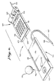
- the cooling cuff 30 (FIGS. 1 and 2) is attached to the calf portion 11 of the patient's leg 12 by one or more straps 126 (two are shown) connected at their ends by hook and loop fasteners 127.
- the cuff can be made small enough to attach to a finger or toe.
- the heat exchanger 31 has a cooling chamber 110, which is formed from a bottom heat exchanger surface 111, a cylindrical sidewall 112 and a top wall 113. Part of injector 130 extends downward through opening 114 in top wall 113. The sidewall 112 and top wall 113 are covered with insulation 116 to limit heat transfer from the outside through those walls into the chamber.
- Cooling surface 111 should be formed of a high heat transmitting material. Gold and silver offer the best heat transmission, but copper or aluminum may be acceptable alternatives especially if plated with a protective non-corroding layer of gold. Cooling surface 111 may be flat, or it may be curved to accommodate the particular appendage being monitored.
- Injecting means which is connected to a source of pressurized liquid having a boiling point at atmospheric pressure less than the temperature to which the skin is to be cooled, injects the liquid into chamber 110 against surface 111.
- the heat transmitted from the body through surface 111 heats the liquid to cause it to boil at atmospheric pressure.
- the phase change from liquid to gas extracts heat from surface 111 which in turn extracts heat from the skin thereby cooling the skin.
- injecting means 130 is described in further detail below, liquid under pressure is injected through orifice 131 (FIG. 3), which is sealed by spring 133 biased check ball valve 132.
- wick 118 on surface 111 causes the liquid to flow along the entire surface.
- Wick 118 may be any wicking material such as fibers, porous stones or screens.
- a wick may also surround spring 133 to transport the liquid to surface 111 and wick 118.
- guide means, a spiral wall 120 (FIGS. 3 and 4) on surface 111 are provided for transporting the fluid from the injecting means to spaced apart locations on the surface. The fluid that is injected into the chamber cannot, therefore, immediately fall to one location on sidewall 112.
- a secondary wick 121 in the form of a fabric or other wicking material in the first winding or two of the spiral directs fluid to the primary wick 118 when the unit is not mounted horizontally. Thereafter, the primary wick 118 will draw fluid along the spiral 120 so that it is exposed to heat transfer surface 111.
- Spiral 120 may have holes or slots near wick 118, which are filled with the wicking material, so that fluid can be transported radially outward in addition to the spiral path.
- the remaining elements of the injecting means are activated by hydraulic control, but the underlying control system upstream from the injecting means is described first.
- Chamber 75 is filled with a propellant e.g. Freon, mixture under pressure so that it is in liquid form.
- Chamber 75 may be disposable and is approximately 3 - 5 cm in diameter.
- a male bayonet fitting 76 at the bottom of chamber 75 mates with a female receiving member 77 in base 70. These valves could operate together so that both open only if the male member 76 of chamber 75 is properly inserted in the female receiving member 77.
- a secondary opening in chamber 75 or valve 76 may be used for filling the chamber 75.
- a leveling sensor 86 (FIG. 7), which is known in the art, is permanently mounted on the base in any desired location (it is shown attached to tank 83 in FIG. 7) to give an audible or other warning or provide a signal to close valve 80 if base 70 is not level sufficiently while chamber 75 is mounted on the base 70.
- the control system could shut valves 102, 106 or 107 in any combination if base 70 is not relatively horizontal.
- a vent 89 may be provided to allow gas at the top of tank 83 to escape to atmosphere during filling. Escape of liquid from vent 89 indicates that tank 83 is filled.
- the bottom of vent 89 should extend downward slightly below gas outlet 78 to provide a reservoir 82 of gas.
- a number of lines with appropriate valves and a vent and gas outlet lead from tank 82. could be provided in chamber 75, but that would complicate the chamber. As chambers 75 may be disposable, it would be undesirable to further complicate them. Therefore, the intermediate tank 83 can accomplish all of the functions of a more complicated tank 75. Each cycle therefore costs less. Other ways of utilizing both the gas and liquid and controlling them could also be provided.
- the inside of tank 83 is shown in FIG. 7. Although it is shown rectangular, the shape can be modified.
- the fluid is divided into a liquid phase 81 and a gaseous or vapor phase 82.
- the fluid is a mixture of Freon fluorocarbons having particular vaporization characteristics and having safe breathing characteristics during venting and normal operation.
- the mixture is chosen such that the boiling point of the gas cools heat exchanger 31 (FIG. 3) to a chosen temperature at a chosen rate.
- the mixture boils below normal skin temperature 37°C but well above freezing 0°C so that frostbite does not occur.
- One outlet 78 of tank 83 (FIG. 7) is located at the top of the tank so that only gas is discharged, and the gas passes through line 79 to valve 107 into pneumatic regulator 84.
- the miniature pneumatic regulator lowers the pressure to a predetermined regulated pressure.
- the pressure in line 79 may vary with temperature of the fluid, and it is desirable to use a regulated pressure for controlling.
- Hydraulic line 85 which is valved at 106, carries liquid, which is reduced in pressure by hydraulic regulator 108, to one input of amplifier 87.
- the low pressure gas from regulator 84 is directed through line 88 into electro-pneumatic converter 91, which is actuated by an electrical signal through line 90 from shaping power circuit 92.
- Circuit 92 converts the analog signal from the sensors, such as thermistors 35 and 36 from line 39, to a useable signal.
- circuit 92 signals electropneumatic converter 91 to permit gas to flow through line 93 into pneumatic amplifier 87.
- electro-pneumatic converter 91 By using low pressure gas in the electro-pneumatic converter 91, only a small valve is needed. Thus, only a small amount of power in line 90 is needed to open the electro-pneumatic converter. Utilizing higher pressure gas or liquid would require more of a power drain.
- electro-pneumatic converter 91 opens, gas flows through line 93 into an input in fluid amplifier 87. Fluid amplifiers are well known. Some are discussed in Tool Engineers Handbook, 2d at 12-15 et seq . (1959). One hydraulic amplifier is discussed in detail in describing Fig. 3.
- amplifier 87 injects hydraulic fluid from line 85 into line 94 at a higher pressure, if desired.
- Cuff 30 (FIG. 3) includes a ballonet about the heat exchanger 31.
- Ballonet 123 comprises a bellows wall 124 and a somewhat flexible top wall 125.
- Cuff 30 is loosely attached to the skin using straps 126.
- a portion of the gas, bled from line 88, is directed through line 96 to a pneumatic regulator 97, which can be mounted in base 70 at or near cuff 30.
- Low pressure gas from pneumatic regulator 97 is then directed through line 109 into ballonet 123 (Fig. 7).
- the pressure in ballonet 123 applies a correct pressure of surface 111 to the skin. If the pressure is too great, the cuff will interfere with circulation and affect readings. Surface 111 and the sensors 35, 36 and 41 should be in contact with the skin.
- a ballonet gauge pressure of between 1.7 and 3.5 kPa is desirable.
- Liquid 81 in tank 83 also flows into line 101 (FIG. 7) where it is controlled by value 102.
- Valves 102 and 106 could be combined with line 85 being connected to line 101 downstream of valve 102, or line 101 could be connected to line 85 downstream from valve 106.
- Relatively high pressure liquid enters injector system 129 (FIGS. 3 and 7) from line 101, and a lower pressure fluid enters through line 94.
- Injector system 129 is located within cuff 30 (FIG. 3) but it could be outside the cuff (see FIG. 7). It is desirable if all lines 94, 101, and 109 entered the cuff through one inlet. Flexible, small diameter tubing with three or more attached tubes is available, and even the electrical leads from sensors 35, 36 and 41 may be attached to the tubes in spaces between them. Preferably, they would all enter the cuff through bellows wall 124 near the skin surface so as not to apply a torque to the cuff and the heat exchanger (FIGS. 2 and 3).
- High pressure liquid in line 101 enters upper chamber 134 where it flows through orifice 136 into main chamber or cell 138 of injector 130.
- Check valve 135 is urged against orifice 136 by spring 137.
- Chamber 138 is formed in part of piston wall 139 which is flexible to allow top wall 140 and upper chamber wall 141 to more up and down in response to pressurization of chambers 138 and 145.
- the spring constants of springs 137 and 133 for check valves 135 and 132 are chosen such that normal maximum pressure in line 101 is sufficient to overcome spring 137 and allow liquid to flow past check valve 135 into main chamber 138, but the pressure is insufficient to overcome the force of spring 133 acting on check valve 132. Therefore, the high pressure liquid is contained within chamber 138.
- the lower pressure liquid through line 94 is fed into control chamber or cell 145 (FIG. 3), which consists of top wall 146 and sidewall 147.
- Bottom wall 148 is mounted to wall 147 by flexible member 149 which permits bottom wall 148 to move up and down between lower ring stop 150 and upper ring stop 151.
- Upper chamber 134 and top wall 140 of injector 130 are connected to bottom wall 148.
- Spring 143 and pressure inside of chamber 138 urges bottom wall 148 upward against stop 151.
- bottom wall 148 When fluid is injected through line 94, the pressure exerts a downward force on bottom wall 148. Because the area of bottom was 148 is very much greater than the area of wall 140 of the main chamber 138, lower pressure in chamber 145 is amplified to force top wall 140 and top chamber 141 downward against the pressure in chamber 138 acting on wall 140. Bottom wall 148 moves down until it contacts bottom ring stop 150. This action greatly pressurizes the inside of main chamber 138 which overcomes the spring force of spring 133 and allows the liquid to be injected through orifice 131 into chamber 110. The check valve 135 prevents the higher pressure liquid from flowing back into line 101.
- the injection system 129 injects a precise amount of the liquid into cooling chamber 110. Minimum power is utilized, and the pressurized working fluids do the work. Neither large electrical power nor high voltage is necessary, and the system is very compact. Also by utilizing a liquid working fluid close the heat exchanger, time lags are substantially reduced or eliminated, and the computing system does not have to compensate for such lags. Changes in outside temperature also have less affect.
- the initiation of the cooling cycle is shown as points 3A, 3B, 3C and 3D on curve 1 and for curve 2, cooling starts at points 4A, 4B, 4C, and 4D (FIG. 5).
- curves 1 and 2 assume a long test with approximately 3.3°C(6°F) temperature changes, the control system permits smaller changes in temperature to decrease test time.
- the control system stops cooling when the temperature of the skin or heat exchanger reaches a predetermined point or after a predetermined interval. In one test, the designed heat exchanger cooled at approximately 1.7°C (3.1°F) per second so that a temperature drop of approximately 17°C (30°F) occurs in ten seconds.
- the shutoff points along curve 1 are indicated as points 5A, 5B, 5C, and 5D and the shutoff points for curve 2 are indicated as 6A, 6B, 6C, and 6D.
- the body works to maintain and return the skin temperature to its normal state.
- the rate at which the skin temperature drops and the rate at which it returns to normal is correlated to the efficiency of the peripheral vascular system. Skin temperature of one with an inefficient vascular system will drop more quickly than that of a normal person. The efficient system may not drop as far, and it will return to normal more quickly.
- the healthy person's skin temperature takes longer to return to normal on the second cycle (point 5A to point 3C) than it does on the first cycle (point 5A to point 3B).
- the person with some disease not only takes longer to return to a normal skin temperature after the first cycle (from 6A to 4B), but the rate of return to normal temperature slows to an even greater degree during subsequent cycles.
- the device plots temperature curves, which trained persons can then read and diagnose conditions.
- the area under those curves can be determined by integration using computer analysis to generate an index, which is called the cardio-thermal index or CTI.
- CTI may be defined, for example, as the summation of the integrals of the temperature recovery portion of the curve over a given number of cycles divided by the summation of the integrals of the cooling portion.
- the result is non-dimensional, and the computer can express the result of a digital number of percentage of normal.
- ⁇ is a summation of all forced cooling integrals to be considered from the first curve through a given number of odd numbered curves.
- the odd cycles are the cooling ones and include the first cycle (3A to 5A), the third cycle (3B to 5B), etc. Each curve is integrated.
- ⁇ ⁇ is a summation of all warming integrals being considered from the second curve through a given even number of curves, which is one larger than the given number during cooling.
- the even cycles are warming cycles and include the second cycle (5A to 3B), the fourth cycle (5B to 3C), etc. Each of those curves is integrated.
- the resulting CTI is very sensitive to blood flow in the capillary bed.
- monitor 50 has two main parts, a console 60 and a base 70.
- Console 60 includes a keyboard 61 that is used to program the control system.
- the keyboard may control the on/off function, or a separate switch 51 (FIG. 7) may control the electrical battery power supply 52.
- Keyboard 61 also inputs at 68 in FIG. 7 different variables such as height, weight, age, sex and location on the skin that the cuff 30 is placed.
- the keyboard 61 could also be used to enter the patient and physician's name, the date and time of the test and other related information so that the printer 61 (FIGS. 6 and 7), which is a standard calculator printer, prints this data for record keeping purposes.
- the keyboard 61 is tied into computer 67 (FIG. 7) that monitors and controls the controller.
- the computer 67 includes a pre-programmed ROM for the basic system controls and for the computation mathematics.
- the console 60 mates with base 70 in the dovetailing grooves 63 and 73 on console 60 and base 70, respectively, which holds the two units together.
- a lock may be provided to prevent separation of the base 70 from the console 60.
- the console could be connected through output line 65 (FIG. 6) to a graphic printer where the analog results of the test are printed and/or to a remote monitoring station in which either analog or digital results could be displayed, for example, at a hospital nursing station.
- the console 60 may also have a digital display 66 for instantaneously monitoring the CTI.
- the temperature sensors on the cuff 30 are thermistors 35 and 36 (FIG. 3), which respond to temperature changes by changes in resistance. A small voltage across the thermistors 35 or 36 is sufficient to read the temperature change.
- a platinum resistance thermistor (PRT) is desirable because of its linearity, but a computer can compensate for nonlinearity.
- a sensor 41 for measuring heat flux could also be provided for additional data. Because of insulation 39 between sensor 35 and the skin, sensor 35 reads the temperature of surface 111; sensor 36 reads skin temperature because of insulation 40 between the sensor and the surface 111.
Landscapes
- Health & Medical Sciences (AREA)
- Life Sciences & Earth Sciences (AREA)
- Medical Informatics (AREA)
- Biophysics (AREA)
- Pathology (AREA)
- Engineering & Computer Science (AREA)
- Biomedical Technology (AREA)
- Heart & Thoracic Surgery (AREA)
- Physics & Mathematics (AREA)
- Molecular Biology (AREA)
- Surgery (AREA)
- Animal Behavior & Ethology (AREA)
- General Health & Medical Sciences (AREA)
- Public Health (AREA)
- Veterinary Medicine (AREA)
- Hematology (AREA)
- Cardiology (AREA)
- Physiology (AREA)
- Thermotherapy And Cooling Therapy Devices (AREA)
Priority Applications (1)
| Application Number | Priority Date | Filing Date | Title |
|---|---|---|---|
| EP88201089A EP0304970A3 (fr) | 1984-03-27 | 1984-03-27 | Echangeur de chaleur pour refroidir un objet |
Applications Claiming Priority (1)
| Application Number | Priority Date | Filing Date | Title |
|---|---|---|---|
| EP88201089A EP0304970A3 (fr) | 1984-03-27 | 1984-03-27 | Echangeur de chaleur pour refroidir un objet |
Related Parent Applications (2)
| Application Number | Title | Priority Date | Filing Date |
|---|---|---|---|
| EP84302083.5 Division | 1984-03-27 | ||
| EP19840302083 Division EP0157962A1 (fr) | 1984-03-27 | 1984-03-27 | Méthode et appareil pour la surveillance du flux sanguin périphérique |
Publications (2)
| Publication Number | Publication Date |
|---|---|
| EP0304970A2 true EP0304970A2 (fr) | 1989-03-01 |
| EP0304970A3 EP0304970A3 (fr) | 1989-05-31 |
Family
ID=8199800
Family Applications (1)
| Application Number | Title | Priority Date | Filing Date |
|---|---|---|---|
| EP88201089A Withdrawn EP0304970A3 (fr) | 1984-03-27 | 1984-03-27 | Echangeur de chaleur pour refroidir un objet |
Country Status (1)
| Country | Link |
|---|---|
| EP (1) | EP0304970A3 (fr) |
Cited By (1)
| Publication number | Priority date | Publication date | Assignee | Title |
|---|---|---|---|---|
| CN115445073A (zh) * | 2022-09-22 | 2022-12-09 | 中国人民解放军陆军特色医学中心 | 一种降温理疗帽 |
Family Cites Families (2)
| Publication number | Priority date | Publication date | Assignee | Title |
|---|---|---|---|---|
| US2010132A (en) * | 1933-05-31 | 1935-08-06 | Bischoff Johannes Christian | Device for cooling the body by means of light volatile chemicals |
| DE2217678A1 (de) * | 1971-04-14 | 1972-10-19 | Leeuwen, Harry Donald van, Greensborough, Victoria (Australien) | Kühlgerät |
-
1984
- 1984-03-27 EP EP88201089A patent/EP0304970A3/fr not_active Withdrawn
Cited By (1)
| Publication number | Priority date | Publication date | Assignee | Title |
|---|---|---|---|---|
| CN115445073A (zh) * | 2022-09-22 | 2022-12-09 | 中国人民解放军陆军特色医学中心 | 一种降温理疗帽 |
Also Published As
| Publication number | Publication date |
|---|---|
| EP0304970A3 (fr) | 1989-05-31 |
Similar Documents
| Publication | Publication Date | Title |
|---|---|---|
| US4569355A (en) | Method and apparatus for monitoring and diagnosing peripheral blood flow | |
| US4756310A (en) | System for cooling an area of the surface of an object | |
| US6398740B1 (en) | Apparatus and method for monitoring the temperatures on the plantar aspects of a human foot and other vital health information | |
| US5678448A (en) | System for continuously measuring forces applied by the foot | |
| EP1028679B1 (fr) | Systeme de regulation thermique d'un patient | |
| EP1226784B1 (fr) | Système de détection de signaux vitaux et méthode de contrôle de santé | |
| US9826936B2 (en) | Body cavity physiological measurement device | |
| EP2911575B1 (fr) | Système de surveillance pour déterminer l'efficacité d'un dispositif de compression | |
| US7490602B2 (en) | Stomach belt for weight loss | |
| US20060282017A1 (en) | Force sensor system for use in monitoring weight bearing | |
| RU2180514C1 (ru) | Способ неинвазивного определения концентрации глюкозы | |
| US20100274105A1 (en) | Body Cavity Physiological Measurement Device | |
| KR20090028632A (ko) | 압력 데이터 프로세싱을 갖는 자가-조정 위 밴드 | |
| KR20140053016A (ko) | 압박장치 | |
| US20040254490A1 (en) | Device for measuring the respiratory rate | |
| US5241965A (en) | Cardiac monitor | |
| EP0157962A1 (fr) | Méthode et appareil pour la surveillance du flux sanguin périphérique | |
| EP0304970A2 (fr) | Echangeur de chaleur pour refroidir un objet | |
| KR101863005B1 (ko) | 의료용 다기능 쿠션 | |
| CA1240765A (fr) | Methode et appareil pour le monitorage de la circulation peripherique en vue de l'etablissement d'un diagnostic | |
| CN109009038A (zh) | 健康监测鞋 | |
| US10709630B2 (en) | Spine table positioner pad with pressure sensing and cooling features | |
| Iberall | Human body as an inconstant heat source and its relation to clothes insulation: Part 2—Experimental investigation into dynamics of the source | |
| CN110124195B (zh) | 中低频治疗仪的主机装置 | |
| JPS60234641A (ja) | 末梢血液流検査方法及び装置 |
Legal Events
| Date | Code | Title | Description |
|---|---|---|---|
| PUAI | Public reference made under article 153(3) epc to a published international application that has entered the european phase |
Free format text: ORIGINAL CODE: 0009012 |
|
| AC | Divisional application: reference to earlier application |
Ref document number: 157962 Country of ref document: EP |
|
| AK | Designated contracting states |
Kind code of ref document: A2 Designated state(s): DE FR GB IT |
|
| PUAL | Search report despatched |
Free format text: ORIGINAL CODE: 0009013 |
|
| AK | Designated contracting states |
Kind code of ref document: A3 Designated state(s): DE FR GB IT |
|
| STAA | Information on the status of an ep patent application or granted ep patent |
Free format text: STATUS: THE APPLICATION IS DEEMED TO BE WITHDRAWN |
|
| 18D | Application deemed to be withdrawn |
Effective date: 19890403 |