EP0304983A1 - Dispositif d'impression avec un rouleau magnétique comprenant une lame ferromagnétique stationnaire en forme de couteau, disposée entre deux pôles magnétiques de même type - Google Patents
Dispositif d'impression avec un rouleau magnétique comprenant une lame ferromagnétique stationnaire en forme de couteau, disposée entre deux pôles magnétiques de même type Download PDFInfo
- Publication number
- EP0304983A1 EP0304983A1 EP88201679A EP88201679A EP0304983A1 EP 0304983 A1 EP0304983 A1 EP 0304983A1 EP 88201679 A EP88201679 A EP 88201679A EP 88201679 A EP88201679 A EP 88201679A EP 0304983 A1 EP0304983 A1 EP 0304983A1
- Authority
- EP
- European Patent Office
- Prior art keywords
- image
- knife blade
- forming element
- sleeve
- magnetic roller
- Prior art date
- Legal status (The legal status is an assumption and is not a legal conclusion. Google has not performed a legal analysis and makes no representation as to the accuracy of the status listed.)
- Granted
Links
Images

Classifications
-
- G—PHYSICS
- G03—PHOTOGRAPHY; CINEMATOGRAPHY; ANALOGOUS TECHNIQUES USING WAVES OTHER THAN OPTICAL WAVES; ELECTROGRAPHY; HOLOGRAPHY
- G03G—ELECTROGRAPHY; ELECTROPHOTOGRAPHY; MAGNETOGRAPHY
- G03G17/00—Electrographic processes using patterns other than charge patterns, e.g. an electric conductivity pattern; Processes involving a migration, e.g. photoelectrophoresis, photoelectrosolography; Processes involving a selective transfer, e.g. electrophoto-adhesive processes; Apparatus essentially involving a single such process
-
- G—PHYSICS
- G03—PHOTOGRAPHY; CINEMATOGRAPHY; ANALOGOUS TECHNIQUES USING WAVES OTHER THAN OPTICAL WAVES; ELECTROGRAPHY; HOLOGRAPHY
- G03G—ELECTROGRAPHY; ELECTROPHOTOGRAPHY; MAGNETOGRAPHY
- G03G15/00—Apparatus for electrographic processes using a charge pattern
- G03G15/22—Apparatus for electrographic processes using a charge pattern involving the combination of more than one step according to groups G03G13/02 - G03G13/20
- G03G15/34—Apparatus for electrographic processes using a charge pattern involving the combination of more than one step according to groups G03G13/02 - G03G13/20 in which the powder image is formed directly on the recording material, e.g. by using a liquid toner
- G03G15/344—Apparatus for electrographic processes using a charge pattern involving the combination of more than one step according to groups G03G13/02 - G03G13/20 in which the powder image is formed directly on the recording material, e.g. by using a liquid toner by selectively transferring the powder to the recording medium, e.g. by using a LED array
- G03G15/348—Apparatus for electrographic processes using a charge pattern involving the combination of more than one step according to groups G03G13/02 - G03G13/20 in which the powder image is formed directly on the recording material, e.g. by using a liquid toner by selectively transferring the powder to the recording medium, e.g. by using a LED array using a stylus or a multi-styli array
-
- G—PHYSICS
- G03—PHOTOGRAPHY; CINEMATOGRAPHY; ANALOGOUS TECHNIQUES USING WAVES OTHER THAN OPTICAL WAVES; ELECTROGRAPHY; HOLOGRAPHY
- G03G—ELECTROGRAPHY; ELECTROPHOTOGRAPHY; MAGNETOGRAPHY
- G03G15/00—Apparatus for electrographic processes using a charge pattern
- G03G15/06—Apparatus for electrographic processes using a charge pattern for developing
- G03G15/08—Apparatus for electrographic processes using a charge pattern for developing using a solid developer, e.g. powder developer
- G03G15/09—Apparatus for electrographic processes using a charge pattern for developing using a solid developer, e.g. powder developer using magnetic brush
- G03G15/0921—Details concerning the magnetic brush roller structure, e.g. magnet configuration
-
- G—PHYSICS
- G03—PHOTOGRAPHY; CINEMATOGRAPHY; ANALOGOUS TECHNIQUES USING WAVES OTHER THAN OPTICAL WAVES; ELECTROGRAPHY; HOLOGRAPHY
- G03G—ELECTROGRAPHY; ELECTROPHOTOGRAPHY; MAGNETOGRAPHY
- G03G2217/00—Details of electrographic processes using patterns other than charge patterns
- G03G2217/0075—Process using an image-carrying member having an electrode array on its surface
Definitions
- This invention relates to a printing device for reproducing information, comprising a movable image-forming element with a dielectric surface, an image-forming station in which a magnetic roller having a rotatable electrically conductive non-magnetic sleeve is disposed near the surface of the image-forming element, means to generate an electric field between the image-forming element and the magnetic roller in accordance with an information pattern, while an electrically conductive magnetically attractable toner powder is present in the zone between the magnetic roller and the image-forming element, and means which generate a magnetic field in the aforesaid zone and comprise a ferromagnetic knife blade disposed stationary inside the sleeve of the magnetic roller and held between like poles of two magnets.
- the object of the invention is to provide a printing device of the kind indicated in the preamble without the above disadvantage.
- the magnets between which the knife blade is held are disposed in mutually offset relationship against the knife blade, the magnet situated in front of the knife blade as considered from the side where the image-forming element leaves the image-forming station, being further away from the knife blade end than the other magnet.
- the magnets are formed by permanent magnets having a magnetic induction greater than or equal to 0.30 T measured at the centre-point of that surface of each magnet which is directed towards the knife blade.
- a ferromagnetic plate is disposed against that side of each of the magnets which is remote from the knife blade, such plate having a thickness of between 0.5 and 2 mm.
- a third magnet is disposed stationary just in front of the magnet fixed against the knife blade, said third magnet being disposed near the sleeve of the magnetic roller.
- an angle of between 78.5° and 83.5° is preferably included by the plane of the knife blade and the tangential plane to the sleeve of the magnetic roller as already defined hereinbefore. This gives an even more optimal form of the magnetic field.
- One aspect that is also improved by this arrangement is the discharge of surplus toner from the toner brush back in the direction of that side where the image-forming element enters the image-forming station. This is achieved by said third magnet, which ensures that the magnetic field is effective over a greater part of the sleeve of the magnetic roller at the entry-side of the image-forming station.
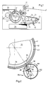
- a magnetic roller 12 is disposed in an image-forming station 11 and comprises a rotatable electrically conductive non-magnetic sleeve and an internal stationary magnet system.
- the rotatable sleeve of the magnetic roller 12 is covered with a uniform layer of electrically conductive and magnetically attractable toner powder, which toner powder is in contact with the image-forming element 10 in an image-forming zone 13.
- a voltage between the magnetic roller 12 and one or more of the selectively controllable electrodes of the image-forming element 10 a powder image is formed on the image-forming element 10. This powder image is transferred by the application of pressure to a heated rubber-covered roller 14.
- a sheet of paper is taken off by roller 25 and this sheet is fed via guide tracks 24 and rollers 22 and 23 to a heating station 19.
- the heating station 19 comprises a belt 21 trained about a heated roller 20.
- the paper sheet is heated by contact with the belt 21.
- the sheet of paper heated in this way is now passed between the rollers 14 and 15, the softened powder image present on the roller 14 being completely transferred to the sheet of paper.
- the temperatures of the belt 21 and the roller 14 are so adapted to one another that the image fuses to the sheet op paper.
- the sheet of paper provided with an image is fed via the conveyor rollers 17 to a collecting tray 18.
- Unit 30 comprises an electronic circuit which converts the optical information of an original into electrical signals which are fed to the controllable electrodes (not shown in detail) via wires 31 provided with sliding contacts and conductive tracks 32 disposed in the insulating side wall of image-forming element 10.
- Fig. 2 is a cross-section through an image-forming element 10 in the form of a drum 36 rotatable in the direction of arrow 35 and provided with an insulating layer 43 on which there is disposed a large number of adjacent mutually insulated electrodes 42 extending endlessly in the direction of movement of the drum and covered by a dielectric layer 41.
- Developing device 84 comprises an earthed sleeve 92 rotatable in the direction of arrow 89 about a ferromagnetic knife blade 88 held between two magnets 86 and 87.
- the thickness of the ferromagnetic knife blade 88 is at least 0.4 mm in order to produce an optimal magnetic flux in the material, while a maximum thickness of about 4 mm is used for constructional reasons.
- the magnets 86 and 87 which are in contact with the knife blade 88 by like poles, generate a narrow magnetic field in the image-forming zone 90, this field emerging from the end of the knife blade 88 which is situated at a short distance from the sleeve 92.
- a feed device e.g. a magnetic brush - a uniform layer of conductive magnetic toner is applied to the dielectric layer 41. This feed takes place in that part of the periphery of the image-forming element 10 which, as considered in the direction of motion, is situated in front of the image-forming zone 90.
- toner powder is conveyed via element 10 to the image-forming zone 90 in order to form a very narrow toner brush under the influence of the directed magnetic field.
- the strongest possible magnetic field is required, having a large magnetic gradient at least on that side where the image-forming element 10 leaves the image-forming zone 90.
- the assembly comprising the knife blade 88 and the magnets 86, 87 is disposed at an angle ⁇ with respect to the line connecting the centres of drum 36 and sleeve 92.
- the angle ⁇ is between 5° and 20°, preferably between 12.5° and 17.5°.
- An additional step to achieve a sharp toner brush comprises disposing the magnets 86, 87 in mutually offset relationship against the knife blade 88. Magnet 87 is positioned much more closely to the end of the knife blade 88 than the magnet 86.
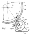
- a feed device applies a uniform layer of conductive magnetic toner to the dielectric layer 41. This feed takes place in the direction of movement of the image-forming element 10 in front of the image-forming zone 160. As a result, toner powder is conveyed via element 10 to the image-forming zone 160 to form a very narrow toner brush under the influence of the directed magnetic field in this zone.
- a ferromagnetic plate 161, 162 is fixed against the magnet 154, 155 respectively on either side of the magnet system, the plate having a thickness of between 0.5 and 2 mm.
- the magnet system of this embodiment is identical to the magnet system as described with respect to Fig. 2.
- the use of the ferromagnetic plates 161, 162 provides less disturbance to the magne tic gradient in the image-forming zone 160.
- the excess toner is entrained by the sleeve 151 and removed therefrom by a stripper 165, for example, and collected in a tray 166.
- FIG. 4 shows a third embodiment of the printing device according to the invention in which an image-forming element 10 of identical structure to that described with respect to Fig. 2 co-operates with a developing device 100.
- This developing device 100 comprises an earthed sleeve 101 which is rotatable in the direction of arrow 102 about a ferromagnetic knife blade 105 held between magnets 106 and 107.
- the magnets 106 and 107 which are in contact with the knife blade 105 by like poles generate a narrow magnetic field in the image-forming zone 108, emerging from the end of the knife blade 105 which is situated at a short distance from the sleeve 101.
- a feed device applies a uniform layer of conductive magnetic toner to the dielectric layer 41. This feed takes place in the direction of movement of the image-forming element 10 in front of the image-forming zone 108. As a result, toner powder is conveyed via element 10 to the image-forming zone 108 to form a very narrow toner brush under the influence of the directed magnetic field in this zone.
- a third magnet 110 is added to the magnet system of the developing device 100.
- the complete magnet system is placed at an agle ⁇ with respect to the line connecting the centres of the drum 36 and the sleeve 101, said angle ⁇ being between 6.5° and 11.5°.
- an arrangement is chosen in which the magnets 106 and 107 are disposed in offset relationship against the knife blade 105, with magnet 107 much closer to the knife blade end than magnet 106. This also contributes to forming a sharp toner brush.
Landscapes
- Physics & Mathematics (AREA)
- General Physics & Mathematics (AREA)
- Health & Medical Sciences (AREA)
- Life Sciences & Earth Sciences (AREA)
- Chemical & Material Sciences (AREA)
- Chemical Kinetics & Catalysis (AREA)
- Electrochemistry (AREA)
- Molecular Biology (AREA)
- Magnetic Brush Developing In Electrophotography (AREA)
- Electrophotography Using Other Than Carlson'S Method (AREA)
- Dry Development In Electrophotography (AREA)
- Printers Or Recording Devices Using Electromagnetic And Radiation Means (AREA)
Applications Claiming Priority (4)
| Application Number | Priority Date | Filing Date | Title |
|---|---|---|---|
| NL8701985A NL8701985A (nl) | 1987-08-25 | 1987-08-25 | Drukinrichting met een magneetrol omvattende een stationair, tussen gelijknamige magneetpolen opgesloten, ferromagnetisch mesblad. |
| NL8701985 | 1987-08-25 | ||
| NL8801309 | 1988-05-20 | ||
| NL8801309A NL8801309A (nl) | 1988-05-20 | 1988-05-20 | Drukinrichting met een magneetrol omvattende een stationair, tussen gelijknamige magneetpolen opgesloten, ferromagnatisch mesblad. |
Publications (2)
| Publication Number | Publication Date |
|---|---|
| EP0304983A1 true EP0304983A1 (fr) | 1989-03-01 |
| EP0304983B1 EP0304983B1 (fr) | 1992-03-04 |
Family
ID=26646284
Family Applications (1)
| Application Number | Title | Priority Date | Filing Date |
|---|---|---|---|
| EP88201679A Expired - Lifetime EP0304983B1 (fr) | 1987-08-25 | 1988-08-03 | Dispositif d'impression avec un rouleau magnétique comprenant une lame ferromagnétique stationnaire en forme de couteau, disposée entre deux pôles magnétiques de même type |
Country Status (7)
| Country | Link |
|---|---|
| US (1) | US4884188A (fr) |
| EP (1) | EP0304983B1 (fr) |
| JP (1) | JPH0816813B2 (fr) |
| KR (1) | KR970004165B1 (fr) |
| AU (1) | AU602233B2 (fr) |
| DE (1) | DE3868785D1 (fr) |
| HK (1) | HK12793A (fr) |
Cited By (9)
| Publication number | Priority date | Publication date | Assignee | Title |
|---|---|---|---|---|
| EP0453031A1 (fr) * | 1990-04-18 | 1991-10-23 | Océ-Nederland B.V. | Méthode de formation d'images visibles, et toneur pulvérulent utilisé pour cette méthode |
| EP0573096A1 (fr) * | 1992-06-04 | 1993-12-08 | Océ-Nederland B.V. | Dispositif de formation d'images |
| EP0718721A1 (fr) | 1994-12-23 | 1996-06-26 | Océ-Nederland B.V. | Procédé d'enregistrement d'images et dispositif d'enregistrement d'images utilisant le procédé |
| EP0773484A1 (fr) | 1995-11-07 | 1997-05-14 | Océ-Nederland B.V. | Système magnétique pour un appareil de formation d'images |
| AU689165B2 (en) * | 1993-12-08 | 1998-03-26 | Oce-Nederland B.V. | An image-forming device and an image-forming element for use therein |
| US5852455A (en) * | 1993-07-23 | 1998-12-22 | Oce-Nederland, B.V. | Image forming device, having separately energizable, inter-connected electrodes and image recording element for use, therein |
| US6795101B2 (en) | 2001-04-27 | 2004-09-21 | Oce-Technologies B.V. | Direct imaging process with feed back control by measuring the amount of toner deposited |
| EP2068205A1 (fr) | 2007-12-07 | 2009-06-10 | Océ-Technologies B.V. | Ensemble couteau magnétique pour dispositif de développement de toner |
| WO2013156311A1 (fr) | 2012-04-19 | 2013-10-24 | Oce-Technologies B.V. | Dispositif de formation d'image comprenant un élément de formation d'image directe |
Families Citing this family (8)
| Publication number | Priority date | Publication date | Assignee | Title |
|---|---|---|---|---|
| JPH04356068A (ja) * | 1990-06-25 | 1992-12-09 | Canon Inc | 画像形成装置 |
| NL9102074A (nl) * | 1991-12-12 | 1993-07-01 | Oce Nederland Bv | Drukinrichting. |
| NL1003680C2 (nl) * | 1996-07-25 | 1998-01-28 | Oce Tech Bv | Beeldafdrukinrichting. |
| JP2001183879A (ja) | 1999-10-12 | 2001-07-06 | Oce Technol Bv | 幽霊像を抑制する方法 |
| WO2004104599A2 (fr) | 2003-05-16 | 2004-12-02 | The Boc Group, Inc. | Procede de nettoyage pour systeme de pesee de controle a resonance magnetique nucleaire |
| KR100728386B1 (ko) * | 2006-02-02 | 2007-06-13 | 엘지전자 주식회사 | 플라즈마 디스플레이 패널의 전극제조방법 및 그 장치 |
| JP5379865B2 (ja) | 2008-12-23 | 2013-12-25 | オセ−テクノロジーズ ビーブイ | 画像形成装置を動作する方法、及び、当該方法の適用のための画像形成装置 |
| KR200487241Y1 (ko) * | 2016-10-28 | 2018-08-27 | 서울특별시 | 대기전력 차단용 검전 플러그 |
Citations (2)
| Publication number | Priority date | Publication date | Assignee | Title |
|---|---|---|---|---|
| US4354454A (en) * | 1979-12-08 | 1982-10-19 | Olympus Optical Company Limited | Developing device with magnetic pole having magnetic spacer members |
| EP0191521A1 (fr) * | 1985-02-06 | 1986-08-20 | Océ-Nederland B.V. | Dispositif d'impression |
Family Cites Families (3)
| Publication number | Priority date | Publication date | Assignee | Title |
|---|---|---|---|---|
| JPS575063A (en) * | 1980-06-13 | 1982-01-11 | Olympus Optical Co Ltd | Magnet roll developing device |
| JPH062416B2 (ja) * | 1984-01-30 | 1994-01-12 | キヤノン株式会社 | 液体噴射記録ヘッドの製造方法 |
| JPS62297865A (ja) * | 1986-06-18 | 1987-12-25 | Hitachi Ltd | 画像記録装置 |
-
1988
- 1988-07-18 KR KR1019880008948A patent/KR970004165B1/ko not_active Expired - Fee Related
- 1988-08-03 EP EP88201679A patent/EP0304983B1/fr not_active Expired - Lifetime
- 1988-08-03 DE DE8888201679T patent/DE3868785D1/de not_active Expired - Lifetime
- 1988-08-17 AU AU21146/88A patent/AU602233B2/en not_active Ceased
- 1988-08-22 JP JP63207985A patent/JPH0816813B2/ja not_active Expired - Lifetime
- 1988-08-23 US US07/235,428 patent/US4884188A/en not_active Expired - Lifetime
-
1993
- 1993-02-18 HK HK127/93A patent/HK12793A/en not_active IP Right Cessation
Patent Citations (2)
| Publication number | Priority date | Publication date | Assignee | Title |
|---|---|---|---|---|
| US4354454A (en) * | 1979-12-08 | 1982-10-19 | Olympus Optical Company Limited | Developing device with magnetic pole having magnetic spacer members |
| EP0191521A1 (fr) * | 1985-02-06 | 1986-08-20 | Océ-Nederland B.V. | Dispositif d'impression |
Non-Patent Citations (2)
| Title |
|---|
| PATENT ABSTRACTS OF JAPAN, vol. 8, no. 58 (P-261)[1495], 16th March 1984; & JP-A-58 207 062 (RICOH K.K.) 02-12-1983 * |
| PATENT ABSTRACTS OF JAPAN, vol. 9, no. 100 (M-376)[1823], 2nd May 1985, page 46 M 376; & JP-A-59 224 369 (FUJI XEROX K.K.) 17-12-1984 * |
Cited By (16)
| Publication number | Priority date | Publication date | Assignee | Title |
|---|---|---|---|---|
| EP0453031A1 (fr) * | 1990-04-18 | 1991-10-23 | Océ-Nederland B.V. | Méthode de formation d'images visibles, et toneur pulvérulent utilisé pour cette méthode |
| US5272033A (en) * | 1990-04-18 | 1993-12-21 | Oce-Nederland B.V. | Method of forming visible images |
| EP0573096A1 (fr) * | 1992-06-04 | 1993-12-08 | Océ-Nederland B.V. | Dispositif de formation d'images |
| JPH0651671A (ja) * | 1992-06-04 | 1994-02-25 | Oce Nederland Bv | 画像形成装置 |
| US5319334A (en) * | 1992-06-04 | 1994-06-07 | Oce-Nederland B.V. | Image forming device |
| US5852455A (en) * | 1993-07-23 | 1998-12-22 | Oce-Nederland, B.V. | Image forming device, having separately energizable, inter-connected electrodes and image recording element for use, therein |
| US5742320A (en) * | 1993-12-08 | 1998-04-21 | Oce-Technologies, B.V. | Image-forming device and an image-forming element for use therein |
| AU689165B2 (en) * | 1993-12-08 | 1998-03-26 | Oce-Nederland B.V. | An image-forming device and an image-forming element for use therein |
| EP0718721A1 (fr) | 1994-12-23 | 1996-06-26 | Océ-Nederland B.V. | Procédé d'enregistrement d'images et dispositif d'enregistrement d'images utilisant le procédé |
| EP0773484A1 (fr) | 1995-11-07 | 1997-05-14 | Océ-Nederland B.V. | Système magnétique pour un appareil de formation d'images |
| US5812921A (en) * | 1995-11-07 | 1998-09-22 | Oce-Nederland, B.V. | Magnet system for an image-forming apparatus |
| US6795101B2 (en) | 2001-04-27 | 2004-09-21 | Oce-Technologies B.V. | Direct imaging process with feed back control by measuring the amount of toner deposited |
| EP2068205A1 (fr) | 2007-12-07 | 2009-06-10 | Océ-Technologies B.V. | Ensemble couteau magnétique pour dispositif de développement de toner |
| US8055168B2 (en) | 2007-12-07 | 2011-11-08 | Oce-Technologies B.V. | Magnet knife assembly for a toner developing device |
| WO2013156311A1 (fr) | 2012-04-19 | 2013-10-24 | Oce-Technologies B.V. | Dispositif de formation d'image comprenant un élément de formation d'image directe |
| US9280083B2 (en) | 2012-04-19 | 2016-03-08 | Oce-Technologies B.V. | Image forming device comprising a direct image forming element |
Also Published As
| Publication number | Publication date |
|---|---|
| HK12793A (en) | 1993-02-26 |
| US4884188A (en) | 1989-11-28 |
| KR890003553A (ko) | 1989-04-15 |
| EP0304983B1 (fr) | 1992-03-04 |
| JPH0816813B2 (ja) | 1996-02-21 |
| JPS6470779A (en) | 1989-03-16 |
| KR970004165B1 (ko) | 1997-03-25 |
| AU602233B2 (en) | 1990-10-04 |
| DE3868785D1 (de) | 1992-04-09 |
| AU2114688A (en) | 1989-03-02 |
Similar Documents
| Publication | Publication Date | Title |
|---|---|---|
| EP0304983B1 (fr) | Dispositif d'impression avec un rouleau magnétique comprenant une lame ferromagnétique stationnaire en forme de couteau, disposée entre deux pôles magnétiques de même type | |
| EP0310209B1 (fr) | Dispositif de formation d'images | |
| CA1038923A (fr) | Systeme de transfert a courroies | |
| US4445771A (en) | Developing apparatus for electrostatic photography | |
| EP0424180A2 (fr) | Appareil d'impression | |
| EP0274895B1 (fr) | Dispositif corona pour charger | |
| US4662311A (en) | Developing device | |
| US4576463A (en) | Developing apparatus for electrostatic photography | |
| EP0546631B1 (fr) | Dispositif d'impression | |
| GB2042278A (en) | Forming electrostatic images | |
| EP0055030A2 (fr) | Procédé et appareil électrographique | |
| US5852455A (en) | Image forming device, having separately energizable, inter-connected electrodes and image recording element for use, therein | |
| US7123868B2 (en) | Electrophotographic printing device having non-grounded electrically conductive layer | |
| EP0573096B1 (fr) | Dispositif de formation d'images | |
| US5083145A (en) | Non-arcing blade printer | |
| US5701564A (en) | Scavengeless development apparatus including an electroded donor roll having a tri-contact commutator assembly | |
| NL8701985A (nl) | Drukinrichting met een magneetrol omvattende een stationair, tussen gelijknamige magneetpolen opgesloten, ferromagnetisch mesblad. | |
| NL8801309A (nl) | Drukinrichting met een magneetrol omvattende een stationair, tussen gelijknamige magneetpolen opgesloten, ferromagnatisch mesblad. | |
| US4833492A (en) | Charge neutralization for plain paper electrography | |
| US4103994A (en) | Recording plate | |
| EP0718721A1 (fr) | Procédé d'enregistrement d'images et dispositif d'enregistrement d'images utilisant le procédé | |
| US4318972A (en) | Method for inducing an electrostatic image in a conductive member | |
| JPS58178378A (ja) | 画像記録装置 | |
| JPS58211172A (ja) | 乾式現像装置 | |
| JP2000118032A (ja) | イオノグラフィ用画像印刷装置 |
Legal Events
| Date | Code | Title | Description |
|---|---|---|---|
| PUAI | Public reference made under article 153(3) epc to a published international application that has entered the european phase |
Free format text: ORIGINAL CODE: 0009012 |
|
| AK | Designated contracting states |
Kind code of ref document: A1 Designated state(s): DE FR GB IT NL SE |
|
| 17P | Request for examination filed |
Effective date: 19890817 |
|
| 17Q | First examination report despatched |
Effective date: 19910506 |
|
| GRAA | (expected) grant |
Free format text: ORIGINAL CODE: 0009210 |
|
| AK | Designated contracting states |
Kind code of ref document: B1 Designated state(s): DE FR GB IT NL SE |
|
| REF | Corresponds to: |
Ref document number: 3868785 Country of ref document: DE Date of ref document: 19920409 |
|
| ITF | It: translation for a ep patent filed | ||
| ET | Fr: translation filed | ||
| PLBE | No opposition filed within time limit |
Free format text: ORIGINAL CODE: 0009261 |
|
| STAA | Information on the status of an ep patent application or granted ep patent |
Free format text: STATUS: NO OPPOSITION FILED WITHIN TIME LIMIT |
|
| 26N | No opposition filed | ||
| EAL | Se: european patent in force in sweden |
Ref document number: 88201679.3 |
|
| NLT1 | Nl: modifications of names registered in virtue of documents presented to the patent office pursuant to art. 16 a, paragraph 1 |
Owner name: OCE-TECHNOLOGIES B.V. |
|
| REG | Reference to a national code |
Ref country code: GB Ref legal event code: IF02 |
|
| PGFP | Annual fee paid to national office [announced via postgrant information from national office to epo] |
Ref country code: NL Payment date: 20030819 Year of fee payment: 16 |
|
| PGFP | Annual fee paid to national office [announced via postgrant information from national office to epo] |
Ref country code: FR Payment date: 20040708 Year of fee payment: 17 |
|
| PGFP | Annual fee paid to national office [announced via postgrant information from national office to epo] |
Ref country code: GB Payment date: 20040712 Year of fee payment: 17 |
|
| PGFP | Annual fee paid to national office [announced via postgrant information from national office to epo] |
Ref country code: DE Payment date: 20040716 Year of fee payment: 17 |
|
| PGFP | Annual fee paid to national office [announced via postgrant information from national office to epo] |
Ref country code: SE Payment date: 20040719 Year of fee payment: 17 |
|
| PG25 | Lapsed in a contracting state [announced via postgrant information from national office to epo] |
Ref country code: NL Free format text: LAPSE BECAUSE OF NON-PAYMENT OF DUE FEES Effective date: 20050301 |
|
| NLV4 | Nl: lapsed or anulled due to non-payment of the annual fee |
Effective date: 20050301 |
|
| PG25 | Lapsed in a contracting state [announced via postgrant information from national office to epo] |
Ref country code: IT Free format text: LAPSE BECAUSE OF NON-PAYMENT OF DUE FEES;WARNING: LAPSES OF ITALIAN PATENTS WITH EFFECTIVE DATE BEFORE 2007 MAY HAVE OCCURRED AT ANY TIME BEFORE 2007. THE CORRECT EFFECTIVE DATE MAY BE DIFFERENT FROM THE ONE RECORDED. Effective date: 20050803 Ref country code: GB Free format text: LAPSE BECAUSE OF NON-PAYMENT OF DUE FEES Effective date: 20050803 |
|
| PG25 | Lapsed in a contracting state [announced via postgrant information from national office to epo] |
Ref country code: SE Free format text: LAPSE BECAUSE OF NON-PAYMENT OF DUE FEES Effective date: 20050804 |
|
| PG25 | Lapsed in a contracting state [announced via postgrant information from national office to epo] |
Ref country code: DE Free format text: LAPSE BECAUSE OF NON-PAYMENT OF DUE FEES Effective date: 20060301 |
|
| EUG | Se: european patent has lapsed | ||
| GBPC | Gb: european patent ceased through non-payment of renewal fee |
Effective date: 20050803 |
|
| PG25 | Lapsed in a contracting state [announced via postgrant information from national office to epo] |
Ref country code: FR Free format text: LAPSE BECAUSE OF NON-PAYMENT OF DUE FEES Effective date: 20060428 |
|
| REG | Reference to a national code |
Ref country code: FR Ref legal event code: ST Effective date: 20060428 |