EP0304992A2 - Procédé d'écriture d'informations binaires sur une couche de mémorisation magnéto-optique et appareil d'enregistrement selon le procédé - Google Patents
Procédé d'écriture d'informations binaires sur une couche de mémorisation magnéto-optique et appareil d'enregistrement selon le procédé Download PDFInfo
- Publication number
- EP0304992A2 EP0304992A2 EP88201747A EP88201747A EP0304992A2 EP 0304992 A2 EP0304992 A2 EP 0304992A2 EP 88201747 A EP88201747 A EP 88201747A EP 88201747 A EP88201747 A EP 88201747A EP 0304992 A2 EP0304992 A2 EP 0304992A2
- Authority
- EP
- European Patent Office
- Prior art keywords
- storage layer
- pulse
- laser beam
- laser
- pulses
- Prior art date
- Legal status (The legal status is an assumption and is not a legal conclusion. Google has not performed a legal analysis and makes no representation as to the accuracy of the status listed.)
- Ceased
Links
Images
Classifications
-
- G—PHYSICS
- G11—INFORMATION STORAGE
- G11B—INFORMATION STORAGE BASED ON RELATIVE MOVEMENT BETWEEN RECORD CARRIER AND TRANSDUCER
- G11B9/00—Recording or reproducing using a method not covered by one of the main groups G11B3/00 - G11B7/00; Record carriers therefor
- G11B9/10—Recording or reproducing using a method not covered by one of the main groups G11B3/00 - G11B7/00; Record carriers therefor using electron beam; Record carriers therefor
-
- G—PHYSICS
- G11—INFORMATION STORAGE
- G11B—INFORMATION STORAGE BASED ON RELATIVE MOVEMENT BETWEEN RECORD CARRIER AND TRANSDUCER
- G11B11/00—Recording on or reproducing from the same record carrier wherein for these two operations the methods are covered by different main groups of groups G11B3/00 - G11B7/00 or by different subgroups of group G11B9/00; Record carriers therefor
- G11B11/10—Recording on or reproducing from the same record carrier wherein for these two operations the methods are covered by different main groups of groups G11B3/00 - G11B7/00 or by different subgroups of group G11B9/00; Record carriers therefor using recording by magnetic means or other means for magnetisation or demagnetisation of a record carrier, e.g. light induced spin magnetisation; Demagnetisation by thermal or stress means in the presence or not of an orienting magnetic field
- G11B11/105—Recording on or reproducing from the same record carrier wherein for these two operations the methods are covered by different main groups of groups G11B3/00 - G11B7/00 or by different subgroups of group G11B9/00; Record carriers therefor using recording by magnetic means or other means for magnetisation or demagnetisation of a record carrier, e.g. light induced spin magnetisation; Demagnetisation by thermal or stress means in the presence or not of an orienting magnetic field using a beam of light or a magnetic field for recording by change of magnetisation and a beam of light for reproducing, i.e. magneto-optical, e.g. light-induced thermomagnetic recording, spin magnetisation recording, Kerr or Faraday effect reproducing
- G11B11/10502—Recording on or reproducing from the same record carrier wherein for these two operations the methods are covered by different main groups of groups G11B3/00 - G11B7/00 or by different subgroups of group G11B9/00; Record carriers therefor using recording by magnetic means or other means for magnetisation or demagnetisation of a record carrier, e.g. light induced spin magnetisation; Demagnetisation by thermal or stress means in the presence or not of an orienting magnetic field using a beam of light or a magnetic field for recording by change of magnetisation and a beam of light for reproducing, i.e. magneto-optical, e.g. light-induced thermomagnetic recording, spin magnetisation recording, Kerr or Faraday effect reproducing characterised by the transducing operation to be executed
- G11B11/1053—Recording on or reproducing from the same record carrier wherein for these two operations the methods are covered by different main groups of groups G11B3/00 - G11B7/00 or by different subgroups of group G11B9/00; Record carriers therefor using recording by magnetic means or other means for magnetisation or demagnetisation of a record carrier, e.g. light induced spin magnetisation; Demagnetisation by thermal or stress means in the presence or not of an orienting magnetic field using a beam of light or a magnetic field for recording by change of magnetisation and a beam of light for reproducing, i.e. magneto-optical, e.g. light-induced thermomagnetic recording, spin magnetisation recording, Kerr or Faraday effect reproducing characterised by the transducing operation to be executed to compensate for the magnetic domain drift or time shift
-
- G—PHYSICS
- G11—INFORMATION STORAGE
- G11B—INFORMATION STORAGE BASED ON RELATIVE MOVEMENT BETWEEN RECORD CARRIER AND TRANSDUCER
- G11B11/00—Recording on or reproducing from the same record carrier wherein for these two operations the methods are covered by different main groups of groups G11B3/00 - G11B7/00 or by different subgroups of group G11B9/00; Record carriers therefor
- G11B11/10—Recording on or reproducing from the same record carrier wherein for these two operations the methods are covered by different main groups of groups G11B3/00 - G11B7/00 or by different subgroups of group G11B9/00; Record carriers therefor using recording by magnetic means or other means for magnetisation or demagnetisation of a record carrier, e.g. light induced spin magnetisation; Demagnetisation by thermal or stress means in the presence or not of an orienting magnetic field
- G11B11/105—Recording on or reproducing from the same record carrier wherein for these two operations the methods are covered by different main groups of groups G11B3/00 - G11B7/00 or by different subgroups of group G11B9/00; Record carriers therefor using recording by magnetic means or other means for magnetisation or demagnetisation of a record carrier, e.g. light induced spin magnetisation; Demagnetisation by thermal or stress means in the presence or not of an orienting magnetic field using a beam of light or a magnetic field for recording by change of magnetisation and a beam of light for reproducing, i.e. magneto-optical, e.g. light-induced thermomagnetic recording, spin magnetisation recording, Kerr or Faraday effect reproducing
- G11B11/10502—Recording on or reproducing from the same record carrier wherein for these two operations the methods are covered by different main groups of groups G11B3/00 - G11B7/00 or by different subgroups of group G11B9/00; Record carriers therefor using recording by magnetic means or other means for magnetisation or demagnetisation of a record carrier, e.g. light induced spin magnetisation; Demagnetisation by thermal or stress means in the presence or not of an orienting magnetic field using a beam of light or a magnetic field for recording by change of magnetisation and a beam of light for reproducing, i.e. magneto-optical, e.g. light-induced thermomagnetic recording, spin magnetisation recording, Kerr or Faraday effect reproducing characterised by the transducing operation to be executed
- G11B11/10504—Recording
- G11B11/10506—Recording by modulating only the light beam of the transducer
-
- G—PHYSICS
- G11—INFORMATION STORAGE
- G11B—INFORMATION STORAGE BASED ON RELATIVE MOVEMENT BETWEEN RECORD CARRIER AND TRANSDUCER
- G11B11/00—Recording on or reproducing from the same record carrier wherein for these two operations the methods are covered by different main groups of groups G11B3/00 - G11B7/00 or by different subgroups of group G11B9/00; Record carriers therefor
- G11B11/10—Recording on or reproducing from the same record carrier wherein for these two operations the methods are covered by different main groups of groups G11B3/00 - G11B7/00 or by different subgroups of group G11B9/00; Record carriers therefor using recording by magnetic means or other means for magnetisation or demagnetisation of a record carrier, e.g. light induced spin magnetisation; Demagnetisation by thermal or stress means in the presence or not of an orienting magnetic field
- G11B11/105—Recording on or reproducing from the same record carrier wherein for these two operations the methods are covered by different main groups of groups G11B3/00 - G11B7/00 or by different subgroups of group G11B9/00; Record carriers therefor using recording by magnetic means or other means for magnetisation or demagnetisation of a record carrier, e.g. light induced spin magnetisation; Demagnetisation by thermal or stress means in the presence or not of an orienting magnetic field using a beam of light or a magnetic field for recording by change of magnetisation and a beam of light for reproducing, i.e. magneto-optical, e.g. light-induced thermomagnetic recording, spin magnetisation recording, Kerr or Faraday effect reproducing
- G11B11/10582—Record carriers characterised by the selection of the material or by the structure or form
- G11B11/10584—Record carriers characterised by the selection of the material or by the structure or form characterised by the form, e.g. comprising mechanical protection elements
Definitions
- the invention relates to a method for writing binary information in a magneto-optical storage layer with the aid of a laser beam of limited duration for one bit at a time, by heating a selected point of the storage layer up to the vicinity of the Curie temperature by the laser beam, and an arrangement for Execution of the procedure.
- Magneto-optical storage layers consist of a ferrimagnetic material, which is often applied with further dielectric layers on a substrate made of glass or plastic.
- the storage layer is premagnetized in a direction perpendicular to the layer plane, and the direction of the magnetization can be reversed by an external magnetic field. This magnetic field need only have a low strength when the material of the storage layer is warmed up to near the Curie temperature.
- this location is heated by a focused laser beam to near the Curie temperature, and an external static magnetic field can be used to switch the magnetization within the heated volume of the storage layer and generate a magnetic domain .
- the information is read out via the Kerr effect, which is a change in the polarization state of the light reflected from the plate as a function of the magneti direction of the storage layer causes.
- the binary value of the information can thus be obtained by evaluating the direction of polarization of the light reflected from the storage layer.
- a method of the type mentioned at the beginning for a rotating storage layer is known, for example, from "PHILIPS Technical Review", vol. 42, no. 2, August 1985, pages 37 to 47.
- the binary information is first converted into channel bits in such a way that at least three bits with the same binary value follow one another, as described in the reference "PHILIPS Technical Review", vol. 40, No. 6, 1982, pages 157 to 164.
- Each bit is written into the memory layer with a laser beam of limited duration, and the bits follow each other so closely that the areas of incidence of the associated laser beams for adjacent bits partially overlap. This creates coherent magnetic domains of different lengths in the storage layer.
- the reliability with which the value of stored information can be read out again is determined by the signal-to-noise ratio, which should be as large as possible.
- This signal-to-noise ratio also depends, among other things, on the processes when the information is written, in particular on the energy or the energy density of the focused laser beam at the point at which the information is to be written, ie which is heated shall be. It has been found in investigations by the applicant that the SNR value increases with increasing radiation energy, but soon strives towards a limit value. The rise and the reaching of the limit value occur earlier, the shorter the impulse with which a certain laser energy approaches heating point of the storage layer is brought. In particular due to the limited laser power, the lower limits of the pulse durations cannot be fallen below, since a minimum energy is also required in order to sufficiently heat the volume at the point to be written.
- the object of the invention is to achieve a higher signal-to-noise ratio SNR without using lasers with a higher pulse power.
- each laser beam of limited duration is divided into several short pulses separated by pulse pauses, which essentially meet the same selected location of the storage layer and of which the energy of each pulse is sufficient, the location of the storage layer irradiated thereby essentially to warm up to near the Curie temperature.
- the invention is essentially based on the finding that with a shorter laser pulse the heat distribution is narrower and thus steeper gradients in the temperature distribution are achieved, so that the domain boundaries become sharper.
- the remagnetization may not be complete, with inhomogeneities in the storage layer also playing a role. If several short laser beam pulses are used to write one bit at a time, which follow each other closely and thus essentially meet the same point even with a fast-rotating laser layer, for example, the heat does not flow so much into the surroundings because there is extensive cooling during the breaks .
- the slight enlargement of the domains does not significantly affect the storage density, since, as mentioned, the domain edges are sharper and, on the other hand, the conditions for reading out become more favorable, since it is then easier to direct the laser beam completely onto the domain when reading.
- the invention also has an advantageous effect when deleting data.
- the risk of possible deletion or deletion of closely adjacent points in the storage layer is also reduced when data is deleted. This applies in particular to a slow relative movement between the storage layer and the laser beam.
- the individual successive impulses and the pauses between them can be of different lengths for optimal results.
- a sufficient improvement compared to individual pulses is achieved according to one embodiment of the invention in that the pulses and the pulse pauses are of essentially the same length.
- Such pulses are very easy to generate and allow sufficient cooling of the heated point in the pulse pauses, so that sharply delimited magnetic domains are obtained.
- An arrangement for carrying out the method according to the invention with a laser which can be controlled by a source of binary information is characterized in that a pulse generator for generating a predetermined number of control pulses of a predetermined length and distance from each information signal is arranged between the information source and the laser and the control pulses control the laser .
- Such pulse generators are known and easy to set up.
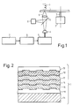
- a plate 1 which carries a magneto-optical storage layer and is preferably rotated continuously by an engine 2 about an axis 3.
- a laser 4 which is expediently designed as a semiconductor laser and which is controlled by a controllable energy source 5, emits a light beam which is focused by an optic 6 onto the plate 1, in particular onto the magneto-optical storage layer thereon.
- the controllable energy source 5 switches the power of the laser 4, which is only low during most operating times and is sufficient for reading out the information stored in the magneto-optical storage layer, when actuated to a high value, which the storage layer at the point hit by the focused laser beam into Heated near the Curie temperature, and by a magnetic field generated simultaneously by the coil 8, the direction of magnetization of the heated point of the storage layer is switched.
- the controllable energy source 5 is controlled by a data source 7, which supplies the information to be stored, via a circuit 8, which will be explained later.
- the reflected laser beam is masked out via the partially transparent mirror 10 and fed to a detector element 11 for evaluating the polarization state.
- FIG. 2 shows a cross section through the plate 1 in FIG. 1.
- This consists in particular of a carrier plate 14 made, for example, of glass approximately 1.2 mm thick, which is covered with a thin photoresist layer 16 approximately 2 ⁇ m thick.
- a trench structure made of concentric rings or a spiral groove is attached in this photoresist layer, preferably by means of a stamp-like tool, under which the photoresist layer is cured, after which the work product is removed.
- the trench structure can also be etched directly into the glass substrate 14, in which case no photoresist layer is used, but this production method is generally more complex.
- an approximately 80 to 90 nm thick layer 16 of aluminum nitride on which the actual magneto-optical storage layer 15 with a thickness of 30 to 50 nm is then attached, which has the composition GdTbFe, TbFeCo or GdTbFeCo, for example.
- Other known magneto-optical memory layers can also be used.
- This is again covered by a layer 17 of aluminum nitride, for example 30 nm thick, and the last is a thin layer 18 of metallic aluminum.
- the layer 17 can also be omitted and serves to increase the thermal sensitivity of the storage layer.
- the polarization direction of the laser light penetrating the storage layer 15 twice is rotated by the Faraday effect due to the reflection on the layer 18 made of metallic aluminum, so that overall a stronger rotation of the polarization in the reflected laser beam is to be expected than can be expected with a simple Kerr effect , occurs.
- the aluminum layer 18 is also covered with a top coat 20 which is intended to protect the aluminum layer against the environment, in particular against mechanical influences and against moisture.
- the width of the trenches in the structure is approximately 1.6 ⁇ m, ie somewhat larger than the magnetic domains generated during writing, the size of which in turn depends on the diameter of the focused laser beam, the thermal properties of the layer structure described and the magnetic properties of the storage layer.
- the magneto-optical storage layer 15 is premagnetized perpendicular to the layer in a uniform direction, for example directed vertically downwards in FIG. 2, and when writing in, a point in a trench is heated by a focused laser beam of higher power until the Curie temperature is reached, and by an external magnetic field this area, ie the volume of the magneto-optical storage layer is switched at this point, i.e. in a direction perpendicular upwards in the assumed example.
- the size of the domain depends, among other things. on the total energy of the laser beam, which is absorbed by the corresponding volume of the magnetic storage layer 15, and this is again a fixed fraction of the laser energy supplied.
- the length of time during which the laser beam of high energy is directed at the writing point also has a very strong influence, since a long pulse generates a wider temperature distribution and forms a domain with an irregular edge. This gives a more noisy signal when reading, so that it is difficult to recover the information.
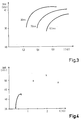
- FIG. 3 shows the SNR values which result at different laser beam energies for different pulse lengths, the SNR values being given in dB and the energy in nJ per laser beam pulse.
- the SNR values for three different pulse lengths are given, namely for 30 ns, 70 ns and 100 ns, in the curves from left to right. It can be seen that with increasing pulse length, higher energies are required for the same SNR values, which amounts to approximately the same power of the laser beam when writing in, except for a pulse duration of 30 ns, where a somewhat higher power is required. Overall, however, it can be seen that with increasing energy the SNR tends towards a saturation value which is higher for shorter pulses than for longer pulses.
- FIG. 4 shows the left curve again shows the SNR values of FIG. 3, which are obtained with a laser beam pulse duration of 30 ns with increasing laser beam energy.
- the SNR is shown when using several pulses with the maximum energy of the left curve indicated by a cross, which follow each other at a distance approximately equal to the pulse length, namely at two, three and four pulses, ie at twice, three times and four times the laser beam energy which is fed to the same domain.
- the optimal number of laser beam pulses ie the optimal total energy, which is about 2 nJ here, depends on various conditions, for example the power of the laser used and the properties of the magneto-optical storage layer used, and can be easily determined in other applications.
- the optimal SNR value would be smaller, however, if the pulse energy of 2 nJ in the present example were applied in a single pulse of 90 ns in this case.
- the most favorable number of laser beam pulses for the best possible SNR value is also influenced by the fact that the distribution of the total energy over several pulses with pulse intervals between them causes an increase in the domain when the disk 1 rotates rapidly in FIG. 1. For example, at a peripheral speed of 5 m / s, the storage layer moved by only 0.15 ⁇ m during a single pulse of 30 ns, which is small compared to the domain size of 1.2 ⁇ m caused by other circumstances mentioned above.
- the total write time is extended to 150 ns, which results in a substantial extension of the domain, ie the laser beam energy supplied at the first moment overlaps only slightly with that at the end energy of the last pulse, so that the area which receives laser beam energy during the entire multiple pulse time is only small.
- the short individual pulses and the pauses between them mean that practically only the irradiated volume of the magneto-optical storage layer is heated and a very steep temperature gradient is created, so that the heat hardly flows into the environment during the pulse, while on the other hand a significant cooling down during the pulse pauses is done with advance is set that each individual laser beam pulse can heat the volume of the magneto-optical storage layer up to the vicinity of the Curie temperature.
- the generation of several pulses in a single information bit to be written is achieved in FIG. 1 by driving a pulse generator 9 from the information bit supplied from the data source 7, which generates several pulses with corresponding pulse pauses for each information bit and thus the energy source 5 of the laser 4 controls.
- a pulse generator can be formed, for example, by a clock generator of a correspondingly high frequency and a counter, as a result of which pulses and pauses are generated with essentially the same duration.
Landscapes
- Physics & Mathematics (AREA)
- Engineering & Computer Science (AREA)
- Plasma & Fusion (AREA)
- Recording Or Reproducing By Magnetic Means (AREA)
Applications Claiming Priority (2)
| Application Number | Priority Date | Filing Date | Title |
|---|---|---|---|
| DE19873728237 DE3728237A1 (de) | 1987-08-25 | 1987-08-25 | Verfahren zum schreiben von binaerer information in eine magnetooptische speicherschicht und anordnung zur durchfuehrung des verfahrens |
| DE3728237 | 1987-08-25 |
Publications (2)
| Publication Number | Publication Date |
|---|---|
| EP0304992A2 true EP0304992A2 (fr) | 1989-03-01 |
| EP0304992A3 EP0304992A3 (fr) | 1990-03-14 |
Family
ID=6334390
Family Applications (1)
| Application Number | Title | Priority Date | Filing Date |
|---|---|---|---|
| EP88201747A Ceased EP0304992A3 (fr) | 1987-08-25 | 1988-08-16 | Procédé d'écriture d'informations binaires sur une couche de mémorisation magnéto-optique et appareil d'enregistrement selon le procédé |
Country Status (5)
| Country | Link |
|---|---|
| US (1) | US4945528A (fr) |
| EP (1) | EP0304992A3 (fr) |
| JP (1) | JPS6470947A (fr) |
| KR (1) | KR890004290A (fr) |
| DE (1) | DE3728237A1 (fr) |
Cited By (1)
| Publication number | Priority date | Publication date | Assignee | Title |
|---|---|---|---|---|
| EP0387052A3 (en) * | 1989-03-09 | 1990-12-05 | Canon Kabushiki Kaisha | Magneto-optical recording apparatus having means for delaying an input signal for preventing bit shift |
Families Citing this family (23)
| Publication number | Priority date | Publication date | Assignee | Title |
|---|---|---|---|---|
| DE69024511T2 (de) * | 1989-02-10 | 1996-06-13 | Toshiba Kawasaki Kk | Gerät zum Verstellen einer Objektivlinse |
| US5963346A (en) * | 1997-12-12 | 1999-10-05 | Northrop Grumman Corporation | Scatter noise reduction in holographic storage systems by two-step write |
| US6016210A (en) * | 1997-12-15 | 2000-01-18 | Northrop Grumman Corporation | Scatter noise reduction in holographic storage systems by speckle averaging |
| US6118560A (en) * | 1998-02-06 | 2000-09-12 | Northrop Grumman Corporation | Scatter noise reduction in holographic storage systems by signal-noise orthogonalization |
| JP2008277586A (ja) * | 2007-04-27 | 2008-11-13 | Toshiba Corp | 磁気素子、磁気記録ヘッド及び磁気記録装置 |
| KR20080108016A (ko) | 2007-06-07 | 2008-12-11 | 가부시끼가이샤 도시바 | 자기 기록 헤드 및 자기 기록 장치 |
| JP4358279B2 (ja) * | 2007-08-22 | 2009-11-04 | 株式会社東芝 | 磁気記録ヘッド及び磁気記録装置 |
| US8994587B2 (en) | 2010-05-14 | 2015-03-31 | Qualcomm Incorporated | Compressed sensing for navigation data |
| JP4919901B2 (ja) | 2007-09-04 | 2012-04-18 | 株式会社東芝 | 磁気記録ヘッド及び磁気記録装置 |
| JP2009070439A (ja) * | 2007-09-11 | 2009-04-02 | Toshiba Corp | 磁気記録ヘッド及び磁気記録装置 |
| JP4929108B2 (ja) | 2007-09-25 | 2012-05-09 | 株式会社東芝 | 磁気ヘッドおよび磁気記録装置 |
| JP2009080878A (ja) | 2007-09-25 | 2009-04-16 | Toshiba Corp | 磁気記録ヘッドおよび磁気記録装置 |
| JP2009080875A (ja) | 2007-09-25 | 2009-04-16 | Toshiba Corp | 磁気ヘッド及び磁気記録装置 |
| JP5376880B2 (ja) * | 2007-09-27 | 2013-12-25 | 株式会社東芝 | 磁気記録ヘッド及び磁気記録装置 |
| JP2010003353A (ja) | 2008-06-19 | 2010-01-07 | Toshiba Corp | 磁気記録ヘッド、磁気ヘッドアセンブリ及び磁気記録装置 |
| JP5377893B2 (ja) * | 2008-06-19 | 2013-12-25 | 株式会社東芝 | 磁気ヘッドアセンブリおよび磁気記録再生装置 |
| JP5361259B2 (ja) | 2008-06-19 | 2013-12-04 | 株式会社東芝 | スピントルク発振子、磁気記録ヘッド、磁気ヘッドアセンブリ及び磁気記録装置 |
| JP2010040060A (ja) * | 2008-07-31 | 2010-02-18 | Toshiba Corp | 高周波アシスト記録用磁気ヘッドおよびそれを用いた磁気記録装置 |
| JP2010040126A (ja) | 2008-08-06 | 2010-02-18 | Toshiba Corp | 磁気記録ヘッド、磁気ヘッドアセンブリ及び磁気記録装置 |
| JP5173750B2 (ja) * | 2008-11-06 | 2013-04-03 | 株式会社東芝 | スピントルク発振子、磁気記録ヘッド、磁気ヘッドアセンブリ及び磁気記録装置 |
| JP5558698B2 (ja) | 2008-11-28 | 2014-07-23 | 株式会社東芝 | 磁気記録ヘッド、磁気ヘッドアセンブリ、磁気記録装置及び磁気記録方法 |
| JP5606482B2 (ja) | 2012-03-26 | 2014-10-15 | 株式会社東芝 | 磁気ヘッド、磁気ヘッドアセンブリ、磁気記録再生装置及び磁気ヘッドの製造方法 |
| KR102265841B1 (ko) * | 2019-07-04 | 2021-06-16 | 주식회사 아이에스원 | 고로 슬래그의 용융 온도 강하제 |
Family Cites Families (5)
| Publication number | Priority date | Publication date | Assignee | Title |
|---|---|---|---|---|
| US3778785A (en) * | 1972-04-20 | 1973-12-11 | Ibm | Method for writing information at nanosecond speeds and a memory system therefor |
| JPS57113402A (en) * | 1981-01-05 | 1982-07-14 | Ricoh Co Ltd | Method and device for vertical thermomagnetic recording |
| US4637008A (en) * | 1984-04-12 | 1987-01-13 | Ltv Aerospace And Defense | Optical erasable disk memory system utilizing duration modulated laser switching |
| JP2605015B2 (ja) * | 1985-06-26 | 1997-04-30 | インターナショナル・ビジネス・マシーンズ・コーポレーション | 熱誘導記録の情報担特信号レコーダ |
| US4811329A (en) * | 1986-06-06 | 1989-03-07 | Mitsubishi Denki Kabushiki Kaisha | Optical head with laser having particular source of driving current |
-
1987
- 1987-08-25 DE DE19873728237 patent/DE3728237A1/de not_active Withdrawn
-
1988
- 1988-08-16 EP EP88201747A patent/EP0304992A3/fr not_active Ceased
- 1988-08-22 JP JP63206492A patent/JPS6470947A/ja active Pending
- 1988-08-22 KR KR1019880010641A patent/KR890004290A/ko not_active Withdrawn
- 1988-08-22 US US07/235,254 patent/US4945528A/en not_active Expired - Fee Related
Cited By (2)
| Publication number | Priority date | Publication date | Assignee | Title |
|---|---|---|---|---|
| EP0387052A3 (en) * | 1989-03-09 | 1990-12-05 | Canon Kabushiki Kaisha | Magneto-optical recording apparatus having means for delaying an input signal for preventing bit shift |
| US5091897A (en) * | 1989-03-09 | 1992-02-25 | Canon Kabushiki Kaisha | Magneto-optical recording apparatus having means for delaying an input signal for preventing bit shift |
Also Published As
| Publication number | Publication date |
|---|---|
| KR890004290A (ko) | 1989-04-21 |
| JPS6470947A (en) | 1989-03-16 |
| EP0304992A3 (fr) | 1990-03-14 |
| DE3728237A1 (de) | 1989-03-09 |
| US4945528A (en) | 1990-07-31 |
Similar Documents
| Publication | Publication Date | Title |
|---|---|---|
| EP0304992A2 (fr) | Procédé d'écriture d'informations binaires sur une couche de mémorisation magnéto-optique et appareil d'enregistrement selon le procédé | |
| DE3687210T2 (de) | Loeschbares, selbstpolarisiertes, thermisches magnetooptisches medium. | |
| DE69023173T2 (de) | Verfahren zur Erhöhung der linearen Schreibdichte in magnetooptischen Speichermedien. | |
| DE3586453T2 (de) | Geraet zum magnetooptischen aufnehmen, wiedergeben und loeschen von daten. | |
| DE3011036C2 (de) | Vorrichtung zur magneto-optischen Aufzeichnung | |
| DE69218986T2 (de) | Magnetooptisches Aufzeichnungsverfahren und magnetooptisches Aufzeichnungs-/Wiedergabegerät | |
| DE60027629T2 (de) | Magnetaufzeichnungsgerät und -methode | |
| DE69128884T2 (de) | Magnetooptisches Wiedergabeverfahren und -vorrichtung | |
| DE2309106B2 (de) | Verfahren zur optischen Informationsspeicherung und Einrichtung zur Durchführung des Verfahrens | |
| DE69225154T2 (de) | Magneto-optische Aufzeichnung | |
| DE3883786T2 (de) | Laserwiedergabegerät. | |
| DE69618881T2 (de) | Vorrichtung und Verfahren zur optischen Aufzeichnung und/oder Wiedergabe von Information | |
| DE3883939T2 (de) | Verfahren zur Informationsaufzeichnung auf einen thermomagnetischen Träger und Vorrichtung zur Durchführung des Verfahrens. | |
| DE69323162T2 (de) | Magnetooptischer Aufzeichnungsträger | |
| DE3883349T2 (de) | Gleichzeitiges Löschen und erneutes Einschreiben einer Information in einen magnetooptischen Speicher. | |
| DE3888296T2 (de) | Optisches Informationsaufzeichnungs- und -löschverfahren. | |
| DE69509000T2 (de) | Thermisches Aufzeichnungsmedium mit konstanter Breite der Markierungsfolge und diesbezügliches Aufzeichnungsverfahren | |
| DE69529442T2 (de) | Informationsaufzeichnungsverfahren und -vorrichtung | |
| DE3706318A1 (de) | Verfahren zum direkten ueberschreiben von digitalen daten, die auf magneto-optischen aufzeichnungsmedien aufgezeichnet sind | |
| DE69225252T2 (de) | Magneto-optisches Aufzeichnungsmedium | |
| DE3203915C2 (fr) | ||
| DE3850430T2 (de) | Verfahren und Gerät zur Aufzeichnung von Daten mit reversibler Phasenänderung. | |
| DE68916084T2 (de) | Optische Informationsaufzeichnungsmethode. | |
| DE69322593T2 (de) | Verfahren und Vorrichtung zur optischen Aufzeichnung | |
| DE69129300T2 (de) | OPTISCHES Wiedergabeverfahren und -vorrichtung |
Legal Events
| Date | Code | Title | Description |
|---|---|---|---|
| PUAI | Public reference made under article 153(3) epc to a published international application that has entered the european phase |
Free format text: ORIGINAL CODE: 0009012 |
|
| AK | Designated contracting states |
Kind code of ref document: A2 Designated state(s): DE FR GB IT NL |
|
| PUAL | Search report despatched |
Free format text: ORIGINAL CODE: 0009013 |
|
| AK | Designated contracting states |
Kind code of ref document: A3 Designated state(s): DE FR GB IT NL |
|
| 17P | Request for examination filed |
Effective date: 19900911 |
|
| 17Q | First examination report despatched |
Effective date: 19920303 |
|
| STAA | Information on the status of an ep patent application or granted ep patent |
Free format text: STATUS: THE APPLICATION HAS BEEN REFUSED |
|
| 18R | Application refused |
Effective date: 19930314 |