EP0305081A2 - Dispositif de fermeture de fenêtre rétractable - Google Patents
Dispositif de fermeture de fenêtre rétractable Download PDFInfo
- Publication number
- EP0305081A2 EP0305081A2 EP88307395A EP88307395A EP0305081A2 EP 0305081 A2 EP0305081 A2 EP 0305081A2 EP 88307395 A EP88307395 A EP 88307395A EP 88307395 A EP88307395 A EP 88307395A EP 0305081 A2 EP0305081 A2 EP 0305081A2
- Authority
- EP
- European Patent Office
- Prior art keywords
- locking element
- locking
- end bar
- ramp
- assembly according
- Prior art date
- Legal status (The legal status is an assumption and is not a legal conclusion. Google has not performed a legal analysis and makes no representation as to the accuracy of the status listed.)
- Granted
Links
- 238000010276 construction Methods 0.000 abstract description 6
- 239000000463 material Substances 0.000 description 5
- 241000238631 Hexapoda Species 0.000 description 3
- 230000004308 accommodation Effects 0.000 description 3
- 230000000717 retained effect Effects 0.000 description 2
- 230000000712 assembly Effects 0.000 description 1
- 238000000429 assembly Methods 0.000 description 1
- 239000011324 bead Substances 0.000 description 1
- 238000003780 insertion Methods 0.000 description 1
- 230000037431 insertion Effects 0.000 description 1
- 239000002184 metal Substances 0.000 description 1
- 230000000149 penetrating effect Effects 0.000 description 1
Images


Classifications
-
- E—FIXED CONSTRUCTIONS
- E06—DOORS, WINDOWS, SHUTTERS, OR ROLLER BLINDS IN GENERAL; LADDERS
- E06B—FIXED OR MOVABLE CLOSURES FOR OPENINGS IN BUILDINGS, VEHICLES, FENCES OR LIKE ENCLOSURES IN GENERAL, e.g. DOORS, WINDOWS, BLINDS, GATES
- E06B9/00—Screening or protective devices for wall or similar openings, with or without operating or securing mechanisms; Closures of similar construction
- E06B9/56—Operating, guiding or securing devices or arrangements for roll-type closures; Spring drums; Tape drums; Counterweighting arrangements therefor
- E06B9/80—Safety measures against dropping or unauthorised opening; Braking or immobilising devices; Devices for limiting unrolling
- E06B9/82—Safety measures against dropping or unauthorised opening; Braking or immobilising devices; Devices for limiting unrolling automatic
- E06B9/86—Safety measures against dropping or unauthorised opening; Braking or immobilising devices; Devices for limiting unrolling automatic against unauthorised opening
-
- E—FIXED CONSTRUCTIONS
- E06—DOORS, WINDOWS, SHUTTERS, OR ROLLER BLINDS IN GENERAL; LADDERS
- E06B—FIXED OR MOVABLE CLOSURES FOR OPENINGS IN BUILDINGS, VEHICLES, FENCES OR LIKE ENCLOSURES IN GENERAL, e.g. DOORS, WINDOWS, BLINDS, GATES
- E06B9/00—Screening or protective devices for wall or similar openings, with or without operating or securing mechanisms; Closures of similar construction
- E06B9/52—Devices affording protection against insects, e.g. fly screens; Mesh windows for other purposes
- E06B9/54—Roller fly screens
-
- E—FIXED CONSTRUCTIONS
- E06—DOORS, WINDOWS, SHUTTERS, OR ROLLER BLINDS IN GENERAL; LADDERS
- E06B—FIXED OR MOVABLE CLOSURES FOR OPENINGS IN BUILDINGS, VEHICLES, FENCES OR LIKE ENCLOSURES IN GENERAL, e.g. DOORS, WINDOWS, BLINDS, GATES
- E06B9/00—Screening or protective devices for wall or similar openings, with or without operating or securing mechanisms; Closures of similar construction
- E06B9/56—Operating, guiding or securing devices or arrangements for roll-type closures; Spring drums; Tape drums; Counterweighting arrangements therefor
- E06B9/80—Safety measures against dropping or unauthorised opening; Braking or immobilising devices; Devices for limiting unrolling
- E06B9/82—Safety measures against dropping or unauthorised opening; Braking or immobilising devices; Devices for limiting unrolling automatic
- E06B9/90—Safety measures against dropping or unauthorised opening; Braking or immobilising devices; Devices for limiting unrolling automatic for immobilising the closure member in various chosen positions
Definitions
- the present invention relates to a retractable window covering assembly, for example a retractable screen or blind assembly.
- One form of such blind particularly an insect blind, or an energy saving blind, includes a spring-loaded roller, blind or screen material wound on the roller, guides along each edge to constrain the edges of the blind or screen material to prevent them from lifting from the plane of the blind or screen, and an end bar which is used to open and close the blind.
- a latch assembly is usually provided at each end of the end bar to lock the blind or screen in the required position.
- blinds or screens may easily be drawn to the desired position and usually the latch at each end will readily engage with a latching plate on the door or on the window frame to lock the frame in the desired position.
- it is relatively difficult to disengage the two latches simultaneously to release the blind so that it may go back towards its retracted position. This is particularly so where the blind has a considerable width.
- blinds are normally considered to be raised and lowered, that it with the axis of the roller horizontal, it is quite common to have the axis vertical particularly when the screen or blind is used on a door or doorway. It will be appreciated that the two latches in such circumstances may be as much as two metres apart which makes their actuation extremely difficult.
- a retractable window covering assembly such as a blind or screen assembly
- a retractable window covering assembly comprising a movable end bar mounted for translation along lateral guide tracks in opposition to a biasing means acting on a window covering member, to return said window covering member to a retracted position and a latch assembly for releasably holding said movable end bar and therewith said window covering member in a required position against retraction by said biasing means
- said latch assembly comprising a first part connected to or integral with said movable end bar,to move with said end bar and a second part locatable in a stationary position with respect to said lateral guide tracks and engageable with, or disengageable from, the first part by translating said end bar along said lateral guide tracks, one of said first and second parts of said latch assembly including a locking element and the other of said parts including a catch member, said locking element having a free end deflectably mounted with respect to said catch member to be deflected in a direction transverse to the direction of movement of
- Such an assembly can be made relatively simply and cheaply and yet can enable very easy operation with one hand.
- the blind In order to lock the blinds in a required position, the blind is moved away from its roller an amount which is slightly greater than that of the desired position.
- the locking member slides along the inclined ramp and can then be moved, or can be arranged to spring, so that it engages against the locking surface to hold the blind or screen in the required position against retraction.
- the locking member is prevented from moving into the return passage by the provision of the stop.
- the end rail when it is desired to retract the blind or screen, all that is necessary is for the end rail to be moved a small distance away from the retracted position so that the locking member passes over the stop and can then be pushed, or can spring, into the return passage along which it can pass to allow the blind or screen to retract.
- the locking element may be provided on the end bar and the catch member may be fixed to the lateral guide.
- the locking element is mounted on the lateral guide and the catch member is mounted on the end bar.
- the locking member is mounted on a support on the end bar and is movable relative to said support and is spring urged relative to said support in a direction to urge said locking element against said locking surface or into said return passage.
- the return passage is adapted to be positioned close to the plane of the blind or screen.
- the other end part of the ramp may extend over said return passage but be movable away to allow said locking member to pass out of said return passage. This may be achieved by the other part of the ramp being resiliently urged to the position covering said return passage for example by being sufficiently flexible to enable it to be moved away by movement of said locking member.
- the second part preferably has an abutment to support said other end part of said ramp to prevent it from moving beyond its normal inclined position in a direction opposite to that in which it flexes, to allow said locking member to pass.
- the second part may include an additional guide ensuring that said locking member moves to the space adjacent said locking surface without accidentially moving past said stop.
- said locking element is mounted at the lower end of at least one of said lateral guide tracks and said catch member is attached to said movable end bar of the corresponding end or ends.
- the locking element may comprise a hook element formed by a resilient wire accommodated within the lower end of said lateral guide track.
- the hook element is engageable by an upstanding projection whereby the end bar may be laterally adjusted with respect to said lateral guide tracks, to allow for dimensional variations of the window, with the projection guiding the hook elements so that the free end thereof can engage said ramp.
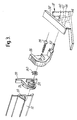
- the blind or screen shown in Figure 1 is illustrated as an insect screen including screen material 10 which is connected, at the top, to a retractable spring loaded roller (not shown) of a perfectly conventional type, and at the lower end to an end bar 12.
- the sides of the screen are guided by side frame members 14 so that the blind cannot readily move in the direction transverse to its plane. This prevents insects from penetrating around the side edges of the screen
- the first part 16 as can be seen in Figure 3 includes a support 20 including a plug 21 for insertion into a hollow portion 22 of the end rail.
- the support 20 is provided with a pivot pin 24 upon which is mounted a pivotal latch 26, the latch being secured to the pivot 24 by a screw 28 and being urged in a generally counterclockwise direction, as seen in Figure 3, by a torsion spring 30.
- the latch 26 includes a laterally extending locking element 32 in the form of a pin.
- the assembly is shown associated with a windowsill 34 on which is mounted a second part 36 of the latch assembly.
- This includes an inclined ramp 38 behind which is positioned a generally rearwardly extending wall member 40, having a lower locking surface 42.
- Behind the rearwardly extending wall member 40 is a generally vertically extending wall 44 including a downwardly extending portion 46 forming a stop member and an upwardly extending portion 48 forming a support wall to be described later.
- An accommodation space 50 is formed below the locking surface 42 and in front of the stop 46. Extending upwardly into this accommodate space is an additional guide 52 which extends in front of the gap 54 below the stop member 46.
- the wall 44 defines the front surface of a return passage 56.
- the ramp 38 includes a lower part 58 and an upper part 60 which is generally flexible and can pivot, because of its flexibility, to the phantom line position 62. Pivoting in the opposite direction is substantially precluded by the upper surface of the support wall 48.
- the blind is pulled down by grasping the end bar 12 and the sequence of operations is shown schematically in Figure 2.
- the locking pin 32 is shown being moved down and is initially in the position A. It engages, at position B, the upper end part 60 of the ramp 38 and then slides down via position C to position D below and in front of the lower end 58 of the ramp 38.
- the action of the spring 30 will then pivot the locking pin 30 first to position E and then to position F at which it is engaged against the locking surface 42. Unwanted further rearward movement of the locking pin is prevented by the stop 46.
- the additional guide 52 is provided to prevent the locking pin 32 from accidentially passing through the gap 54 below the stop 46. With the locking pin in the position F the blind will be retained in this position.
- the spring loading of the locking member can be omitted and the latching and unlatching can be effected by manual movement, causing the locking member 32 to move along the path A, B, C, D, E, F, G, H.
- the provision of the spring loaded member 26 with the locking pin 32 thereupon greatly facilitates the operation.
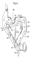
- the screen material 110 is provided with an end bar 112 and the sides of the screen are guided by side frame members 114 as previously.
- the latch assembly 118 includes a part 136 ( Figure 5) formed integrally with or inserted into the end of the end bar 112, which includes an inclined ramp 138 which is formed as a separate element, e.g. of spring metal, mounted on a body portion 140 of the part 136 having an upper locking surface 142.
- Behind the body portion 140 is a generally vertically extending wall 144, including an upwardly extending portion 146 forming a stop member and a downwardly extending portion 148 forming a support wall to be described later.
- An accommodation space 150 is formed above the locking surface 142 and in front of the stop 146. Extending downwardly into this accommodation space is an additional guide 152 which extends in front of the gap 154 above the stop member 146.
- the wall 144 defines the front surface of a return passage 156.
- the ramp 138 includes a lower part 158, formed in the shape of inverted U, and a lower part 160 which is generally flexible and can pivot to the phantom line position 162. Pivoting in the opposite direction is substantially precluded by the lower surface of the support wall 148.
- a projection 170 is mounted to extend laterally below the lower end of the passage 156.
- a wire hook member 116 Carried in a portion of the side frame 114 is a wire hook member 116 which forms a first part of the latch assembly.
- This hook is formed of wire material and includes lower web portion 123, a first leg 119, a second leg 121 and an inclined resilient arm 117 having, at its free end, an inturned end 132 forming a locking element.
- the first leg 119 is engaged in one of two inturned beads 115 formed on the guide frame member 114.
- the operation is very similar to that of Figures 1 to 3.
- the blind is pulled down by grasping the end bar 112 and the sequence of operations is shown schematically in Figure 5.
- the locking element 132 is shown being moved relatively upwardly (since the end bar 112 is being moved downwardly) and is initially in the position A. It engages, at position B, the lower end part 160 of the ramp 138 and then slides up via the position C to the position D above and in front of the upper end part 158 of the ramp 138.
- the action of the resilience of the arm 117 will then pivot the locking element 132 first to the position E and then to the position F at which it is engaged against the locking surface 142. Unwanted further rearward movement of the locking element 132 is prevented by the stop 146.
- the additional guide 152 prevents the locking element 132 from accidentally passing through the gap 154 above the stop 146. With the locking element in position F, the blind will be retained in this position.
Landscapes
- Engineering & Computer Science (AREA)
- Structural Engineering (AREA)
- Architecture (AREA)
- Civil Engineering (AREA)
- Life Sciences & Earth Sciences (AREA)
- Insects & Arthropods (AREA)
- Pest Control & Pesticides (AREA)
- Operating, Guiding And Securing Of Roll- Type Closing Members (AREA)
- Window Of Vehicle (AREA)
Applications Claiming Priority (2)
| Application Number | Priority Date | Filing Date | Title |
|---|---|---|---|
| GB8720178A GB2211540A (en) | 1987-08-27 | 1987-08-27 | Latch for blind |
| GB8720178 | 1987-08-27 |
Publications (3)
| Publication Number | Publication Date |
|---|---|
| EP0305081A2 true EP0305081A2 (fr) | 1989-03-01 |
| EP0305081A3 EP0305081A3 (en) | 1989-06-07 |
| EP0305081B1 EP0305081B1 (fr) | 1991-10-16 |
Family
ID=10622869
Family Applications (1)
| Application Number | Title | Priority Date | Filing Date |
|---|---|---|---|
| EP19880307395 Expired EP0305081B1 (fr) | 1987-08-27 | 1988-08-10 | Dispositif de fermeture de fenêtre rétractable |
Country Status (4)
| Country | Link |
|---|---|
| EP (1) | EP0305081B1 (fr) |
| DE (1) | DE3865598D1 (fr) |
| ES (1) | ES2025781T3 (fr) |
| GB (1) | GB2211540A (fr) |
Cited By (11)
| Publication number | Priority date | Publication date | Assignee | Title |
|---|---|---|---|---|
| EP0579335A1 (fr) * | 1992-07-13 | 1994-01-19 | Hamstra-Weesp B.V. | Moustiquaire enroulable |
| EP0790384A1 (fr) * | 1996-02-19 | 1997-08-20 | Hunter Douglas Industries B.V. | Fermeture rétractable |
| NL1007445C2 (nl) * | 1997-11-04 | 1999-05-06 | Windvast N V | Zonwering met blokkeringsinrichting. |
| FR2771132A1 (fr) * | 1997-11-18 | 1999-05-21 | Manuf De Stores Du Languedoc | Dispositif de store interieur enroulable destine a etre utilise sur un chassis vertical, horizontal ou incline |
| EP1816306A3 (fr) * | 2006-02-06 | 2009-07-08 | Stanislav Jurhar | Un élément guide pour l'ancrage d'un store roulant |
| ITBO20090451A1 (it) * | 2009-07-14 | 2011-01-15 | Fanani S R L | Gruppo di bloccaggio, particolarmente per tende da esterni. |
| CN102128006A (zh) * | 2011-02-21 | 2011-07-20 | 胡培中 | 防风隐形纱窗锁扣结构 |
| WO2011101879A1 (fr) * | 2010-02-22 | 2011-08-25 | Corradi S.P.A. | Dispositif de verrouillage mécanique, particulièrement pour des rideaux qui coulissent sur des glissières et analogues |
| EP2500508A1 (fr) | 2011-03-16 | 2012-09-19 | Zurflüh-Feller | Installation de fermeture ou de protection solaire, et procédé de mise en oeuvre d'une telle installation |
| WO2015087096A1 (fr) * | 2013-12-12 | 2015-06-18 | Traex-Bau Kft | Dispositif de verrouillage pour la barre poignée d'une grille de protection contre les insectes roulante |
| CN108138535A (zh) * | 2015-10-30 | 2018-06-08 | 伦森防晒屏公司 | 用于导引竖立屏幕的导引装置和用于在门或框架型材上安装这种导引装置的导引型材的方法 |
Families Citing this family (3)
| Publication number | Priority date | Publication date | Assignee | Title |
|---|---|---|---|---|
| GB2291465A (en) * | 1994-07-16 | 1996-01-24 | Heywood Williams Ltd | Cabinet latch |
| FR2966189B1 (fr) | 2010-10-15 | 2012-11-30 | Somfy Sas | Dispositif de blocage d'une barre de charge d'un ecran et installation de fermeture ou de protection solaire equipee d'un tel dispositif de blocage |
| CN104653083B (zh) * | 2015-01-19 | 2016-09-07 | 中北大学 | 一种隐形纱窗 |
Family Cites Families (8)
| Publication number | Priority date | Publication date | Assignee | Title |
|---|---|---|---|---|
| GB762202A (en) * | 1954-02-02 | 1956-11-28 | Gen Electric Co Ltd | Improvements in or relating to lighting fittings including support mechanisms for detachable reflectors |
| CH443987A (de) * | 1966-03-26 | 1967-09-15 | Barmag Barmer Maschf | Vorrichtung zum Betätigen einer verstellbaren Einrichtung, insbesondere einer Bremse oder Kupplung, an einer Textilmaschine |
| US3436983A (en) * | 1967-08-08 | 1969-04-08 | Coastal Dynamics Corp | Latch structure for pull lines |
| ZA727861B (en) * | 1972-11-06 | 1974-02-27 | C Boemer | Automatic locking of high-level luminairs |
| DE2645422A1 (de) * | 1976-10-08 | 1978-04-13 | Porsche Ag | Diebstahlsicherung fuer kraftfahrzeuge |
| GB2117472A (en) * | 1982-03-25 | 1983-10-12 | Alan John Richmond | Mechanism for retaining two members in two different relative positions |
| US4662423A (en) * | 1982-10-31 | 1987-05-05 | Kabushiki Kaisha Nichibei | Device for operating roll-screen |
| IT1157068B (it) * | 1982-11-09 | 1987-02-11 | Serafini Giovanni Abatenda | Armatura per tenda da sole trasformabile in armatura per tenda da veranda |
-
1987
- 1987-08-27 GB GB8720178A patent/GB2211540A/en not_active Withdrawn
-
1988
- 1988-08-10 DE DE8888307395T patent/DE3865598D1/de not_active Expired - Fee Related
- 1988-08-10 ES ES88307395T patent/ES2025781T3/es not_active Expired - Lifetime
- 1988-08-10 EP EP19880307395 patent/EP0305081B1/fr not_active Expired
Cited By (14)
| Publication number | Priority date | Publication date | Assignee | Title |
|---|---|---|---|---|
| EP0579335A1 (fr) * | 1992-07-13 | 1994-01-19 | Hamstra-Weesp B.V. | Moustiquaire enroulable |
| EP0790384A1 (fr) * | 1996-02-19 | 1997-08-20 | Hunter Douglas Industries B.V. | Fermeture rétractable |
| NL1007445C2 (nl) * | 1997-11-04 | 1999-05-06 | Windvast N V | Zonwering met blokkeringsinrichting. |
| EP0915214A1 (fr) * | 1997-11-04 | 1999-05-12 | Windvast N.V. | Store pourvu d'un dispositif de blocage |
| FR2771132A1 (fr) * | 1997-11-18 | 1999-05-21 | Manuf De Stores Du Languedoc | Dispositif de store interieur enroulable destine a etre utilise sur un chassis vertical, horizontal ou incline |
| EP1816306A3 (fr) * | 2006-02-06 | 2009-07-08 | Stanislav Jurhar | Un élément guide pour l'ancrage d'un store roulant |
| ITBO20090451A1 (it) * | 2009-07-14 | 2011-01-15 | Fanani S R L | Gruppo di bloccaggio, particolarmente per tende da esterni. |
| WO2011006874A1 (fr) * | 2009-07-14 | 2011-01-20 | Fanani S.R.L. | Ensemble de verrouillage, particulièrement pour auvents extérieurs |
| WO2011101879A1 (fr) * | 2010-02-22 | 2011-08-25 | Corradi S.P.A. | Dispositif de verrouillage mécanique, particulièrement pour des rideaux qui coulissent sur des glissières et analogues |
| CN102128006A (zh) * | 2011-02-21 | 2011-07-20 | 胡培中 | 防风隐形纱窗锁扣结构 |
| EP2500508A1 (fr) | 2011-03-16 | 2012-09-19 | Zurflüh-Feller | Installation de fermeture ou de protection solaire, et procédé de mise en oeuvre d'une telle installation |
| FR2972754A1 (fr) * | 2011-03-16 | 2012-09-21 | Zurfluh Feller | Installation de fermeture ou de protection solaire, et procede de mise en oeuvre d'une telle installation |
| WO2015087096A1 (fr) * | 2013-12-12 | 2015-06-18 | Traex-Bau Kft | Dispositif de verrouillage pour la barre poignée d'une grille de protection contre les insectes roulante |
| CN108138535A (zh) * | 2015-10-30 | 2018-06-08 | 伦森防晒屏公司 | 用于导引竖立屏幕的导引装置和用于在门或框架型材上安装这种导引装置的导引型材的方法 |
Also Published As
| Publication number | Publication date |
|---|---|
| EP0305081B1 (fr) | 1991-10-16 |
| DE3865598D1 (de) | 1991-11-21 |
| ES2025781T3 (es) | 1992-04-01 |
| GB8720178D0 (en) | 1987-10-07 |
| GB2211540A (en) | 1989-07-05 |
| EP0305081A3 (en) | 1989-06-07 |
Similar Documents
| Publication | Publication Date | Title |
|---|---|---|
| EP0305081B1 (fr) | Dispositif de fermeture de fenêtre rétractable | |
| JP2620808B2 (ja) | 垂直遮蔽組立体 | |
| US11927039B2 (en) | Latch mechanism | |
| US4768243A (en) | Latch for a drop side crib | |
| US4646808A (en) | Cordlock structure for a blind assembly | |
| PL177890B1 (pl) | Blokada rolety okiennej lub drzwiowej | |
| US4607870A (en) | Door security device | |
| US4443915A (en) | Cord locking device for a sun-blind or the like | |
| GB2301621A (en) | Window or like stay | |
| US6085823A (en) | Covering assembly for an architectural opening | |
| KR950010990B1 (ko) | 창 자물쇠 | |
| JP3508974B2 (ja) | キャビネットにおける開閉扉及び抽斗の選択式ロック装置 | |
| CN218092579U (zh) | 推拉窗和工程机械驾驶室 | |
| JP4075232B2 (ja) | シャッターの施解錠装置 | |
| EP0860577B1 (fr) | Couverture pour ouverture architectonique | |
| US4226455A (en) | Locking device for raisable venetian blind | |
| JP3906466B2 (ja) | シャッター | |
| GB2124692A (en) | Fastening for sliding doors, windows or the like | |
| EP0396793B1 (fr) | Dispositif destiné à maintenir en position ouverte des volets de portes ou fenêtres | |
| JP3884679B2 (ja) | 開閉装置 | |
| JP3077641B2 (ja) | シャッター用施錠装置 | |
| EP0342164A2 (fr) | Fermeture pour volets ou similaires | |
| JPH08109780A (ja) | シャッターの施錠装置 | |
| JP3242962B2 (ja) | 雨戸の開閉駆動装置 | |
| JPH0663798U (ja) | シャッターの施錠機構 |
Legal Events
| Date | Code | Title | Description |
|---|---|---|---|
| PUAI | Public reference made under article 153(3) epc to a published international application that has entered the european phase |
Free format text: ORIGINAL CODE: 0009012 |
|
| AK | Designated contracting states |
Kind code of ref document: A2 Designated state(s): DE ES FR GB IT NL |
|
| PUAL | Search report despatched |
Free format text: ORIGINAL CODE: 0009013 |
|
| AK | Designated contracting states |
Kind code of ref document: A3 Designated state(s): DE ES FR GB IT NL |
|
| 17P | Request for examination filed |
Effective date: 19890926 |
|
| 17Q | First examination report despatched |
Effective date: 19900426 |
|
| GRAA | (expected) grant |
Free format text: ORIGINAL CODE: 0009210 |
|
| AK | Designated contracting states |
Kind code of ref document: B1 Designated state(s): DE ES FR GB IT NL |
|
| REF | Corresponds to: |
Ref document number: 3865598 Country of ref document: DE Date of ref document: 19911121 |
|
| ET | Fr: translation filed | ||
| ITF | It: translation for a ep patent filed | ||
| REG | Reference to a national code |
Ref country code: ES Ref legal event code: FG2A Ref document number: 2025781 Country of ref document: ES Kind code of ref document: T3 |
|
| PLBE | No opposition filed within time limit |
Free format text: ORIGINAL CODE: 0009261 |
|
| STAA | Information on the status of an ep patent application or granted ep patent |
Free format text: STATUS: NO OPPOSITION FILED WITHIN TIME LIMIT |
|
| PGFP | Annual fee paid to national office [announced via postgrant information from national office to epo] |
Ref country code: NL Payment date: 19920831 Year of fee payment: 5 |
|
| 26N | No opposition filed | ||
| PGFP | Annual fee paid to national office [announced via postgrant information from national office to epo] |
Ref country code: GB Payment date: 19930730 Year of fee payment: 6 |
|
| PGFP | Annual fee paid to national office [announced via postgrant information from national office to epo] |
Ref country code: ES Payment date: 19930803 Year of fee payment: 6 |
|
| PGFP | Annual fee paid to national office [announced via postgrant information from national office to epo] |
Ref country code: FR Payment date: 19930805 Year of fee payment: 6 |
|
| PGFP | Annual fee paid to national office [announced via postgrant information from national office to epo] |
Ref country code: DE Payment date: 19930806 Year of fee payment: 6 |
|
| PG25 | Lapsed in a contracting state [announced via postgrant information from national office to epo] |
Ref country code: NL Effective date: 19940301 |
|
| NLV4 | Nl: lapsed or anulled due to non-payment of the annual fee | ||
| PG25 | Lapsed in a contracting state [announced via postgrant information from national office to epo] |
Ref country code: GB Effective date: 19940810 |
|
| PG25 | Lapsed in a contracting state [announced via postgrant information from national office to epo] |
Ref country code: ES Free format text: LAPSE BECAUSE OF EXPIRATION OF PROTECTION Effective date: 19940811 |
|
| GBPC | Gb: european patent ceased through non-payment of renewal fee |
Effective date: 19940810 |
|
| PG25 | Lapsed in a contracting state [announced via postgrant information from national office to epo] |
Ref country code: FR Effective date: 19950428 |
|
| PG25 | Lapsed in a contracting state [announced via postgrant information from national office to epo] |
Ref country code: DE Effective date: 19950503 |
|
| REG | Reference to a national code |
Ref country code: FR Ref legal event code: ST |
|
| REG | Reference to a national code |
Ref country code: ES Ref legal event code: FD2A Effective date: 19990601 |
|
| PG25 | Lapsed in a contracting state [announced via postgrant information from national office to epo] |
Ref country code: IT Free format text: LAPSE BECAUSE OF NON-PAYMENT OF DUE FEES Effective date: 20050810 |