EP0305577A1 - Empfängnisverhütende Intrauterinvorrichtung - Google Patents
Empfängnisverhütende Intrauterinvorrichtung Download PDFInfo
- Publication number
- EP0305577A1 EP0305577A1 EP87112901A EP87112901A EP0305577A1 EP 0305577 A1 EP0305577 A1 EP 0305577A1 EP 87112901 A EP87112901 A EP 87112901A EP 87112901 A EP87112901 A EP 87112901A EP 0305577 A1 EP0305577 A1 EP 0305577A1
- Authority
- EP
- European Patent Office
- Prior art keywords
- bar
- rod
- intrauterine device
- base
- elastic
- Prior art date
- Legal status (The legal status is an assumption and is not a legal conclusion. Google has not performed a legal analysis and makes no representation as to the accuracy of the status listed.)
- Granted
Links
Images
Classifications
-
- A—HUMAN NECESSITIES
- A61—MEDICAL OR VETERINARY SCIENCE; HYGIENE
- A61F—FILTERS IMPLANTABLE INTO BLOOD VESSELS; PROSTHESES; DEVICES PROVIDING PATENCY TO, OR PREVENTING COLLAPSING OF, TUBULAR STRUCTURES OF THE BODY, e.g. STENTS; ORTHOPAEDIC, NURSING OR CONTRACEPTIVE DEVICES; FOMENTATION; TREATMENT OR PROTECTION OF EYES OR EARS; BANDAGES, DRESSINGS OR ABSORBENT PADS; FIRST-AID KITS
- A61F6/00—Contraceptive devices; Pessaries; Applicators therefor
- A61F6/06—Contraceptive devices; Pessaries; Applicators therefor for use by females
- A61F6/14—Contraceptive devices; Pessaries; Applicators therefor for use by females intra-uterine type
- A61F6/142—Wirelike structures, e.g. loops, rings, spirals
- A61F6/144—Wirelike structures, e.g. loops, rings, spirals with T-configuration
Definitions
- the invention relates to a contraceptive intrauterine device with a bar with rounded ends, with a rod connected to the bar and forming a T-shaped element with it, with an element designed as an elastic loop for holding the intrauterine device within the uterine cavity and with one on the bar coiled spiral.
- a contraceptive intrauterine device which consists of a T-shaped element which is formed by a rod and two radially projecting elastic strips. An elastic loop is arranged at the end of the element.
- the equally curved strips each have a sufficiently large radius of curvature. The angle between the bar and each strip is less than 90 °.
- the contraceptive effect of the device is insufficient. Because the elasticity of the loop is insufficient and the Loop is very large, the mucous membrane in the area of the inner cervix can be damaged or irritated, which can lead to an arbitrary expulsion of the intrauterine device.
- Another contraceptive intrauterine device (Nova T / Cu 200 Ag from the company Khukhtamyaki, Leiras, Finland) consists of a rod with a copper spiral wound thereon, a strip with rounded ends attached to the rod, which forms a T-shaped element with the rod, and an elastic loop attached to the end of the rod to hold the entire intrauterine device within the uterine cavity.
- the base bow of the elastic loop irritates the receptors of the mucous membrane of the inner cervix of the cervix and causes strong contractions of the muscles of the uterus, which can lead to device expulsion.
- the device on which the invention is based consists in designing the contraceptive intrauterine device of the type mentioned at the outset in such a way that the same size of the device can be used for uterine cavities of different sizes, shapes and positions.
- the contraceptive intrauterine device of the generic type in that the element for holding the entire intrauterine device within the uterine cavity has a base arch and two elastic feet connected to the base arch, which are fastened to the bar at the base of the rod in the plane formed by the rod and the bar and embrace the rod.
- the base bow of the elastic loop is expediently made reinforced to form a support over the cervix.
- a contraceptive intrauterine device constructed in this way makes it possible for the groin to be pressed against the mucous membrane of the uterine base of a uterus of any size, shape and position as a result of the elastic effect of the holding element consisting of the reinforced base arch and its elastic feet, thereby ensuring the desired contraceptive effect becomes.
- the holding element prevents the intrauterine device from penetrating into the area of the inner mouth of the cervix. It stays in position this area without damaging receptors so that an expulsion is avoided.
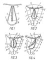
- the contraceptive intrauterine device shown in the drawing has a bar 1 with rounded ends and a bar 2 connected to bar 1 so that bar 1 and bar 2 form a T-shaped element, the bar with bar 1 at its base connected is.
- a spiral or helix 5 is arranged on the rod 2.
- An element 3, which is designed as an elastic loop, serves to hold the intrauterine device within the uterine cavity 4.
- the elastic loop is formed by a reinforced base arch 6 and two elastic feet 7 connected to the base arch 6, which are fastened to the bar 1 next to the base of the rod 2.
- the elastic loop forming the element 3 lies in that of the rod 2 and the bar 1 formed level and includes the rod 2nd
- the intrauterine device is inserted into the uterine cavity 4 via the cervix 8 (FIG. 2) and pressed with the groin 1 against the mucous membrane 9 of the uterus.
- the reinforced base arch 6 of the element 3 abuts against the uterine wall 10 at a sufficient distance from the area of the cervix 11.
- the element 3 When the intrauterine device is inserted into a larger transverse dimension uterine cavity 4, i.e. is inserted into a shortened uterine cavity 4, as shown in Fig. 3, the element 3 also shortens due to its spring property and keeps the groin 1 in tight contact with the mucous membrane 9 of the uterus.
- the element 3 When the intrauterine device is inserted into a uterine cavity 4 with an enlarged longitudinal dimension and a deformed shape, as shown in FIG. 4, the element 3 also becomes longer due to its spring properties and adapts to the shape of the uterine cavity 4 so that the ridge 1 in turn is pressed close to the mucous membrane 9 of the base of the uterus.
- the reinforced base arch 6 of the resilient holding element 3 ensures that the intrauterine device is reliably held within the uterine cavity 4 above the cervix 11 and prevents expulsion. Due to the resilient elastic property of the element 3, the bar 1 of the intrauterine device lasts in close contact with the mucous membrane 9 of the base of the uterus and acts on it as a mechanical seal.
- the contraceptive intrauterine device is in this Design required only in a single size, since it adapts to the different shape, size and position of the uterus, so that the desired contraceptive effect is guaranteed.
Landscapes
- Health & Medical Sciences (AREA)
- Reproductive Health (AREA)
- Engineering & Computer Science (AREA)
- Biomedical Technology (AREA)
- Heart & Thoracic Surgery (AREA)
- Vascular Medicine (AREA)
- Life Sciences & Earth Sciences (AREA)
- Animal Behavior & Ethology (AREA)
- General Health & Medical Sciences (AREA)
- Public Health (AREA)
- Veterinary Medicine (AREA)
- Orthopedics, Nursing, And Contraception (AREA)
- Absorbent Articles And Supports Therefor (AREA)
- Physical Or Chemical Processes And Apparatus (AREA)
- Surgical Instruments (AREA)
Abstract
Description
- Die Erfindung betrifft eine empfängnisverhütende Intrauterinvorrichtung mit einer Leiste mit abgerundeten Enden, mit einem mit der Leiste verbundenen und mit ihr ein T-förmiges Element bildenden Stab, mit einem als elastische Schleife ausgeführten Element zum Halten der Intrauterinvorrichtung innerhalb der Gebärmutterhöhle und mit einer auf dem Stab aufgewickelten Spirale.
- Aus der GB-B-14 56 746 ist bereits eine empfängnisverhütende Intrauterinvorrichtung bekannt, die aus einem T-förmigen Element besteht, das von einem Stab und zwei radial abstehenden elastischen Streifen gebildet wird. Am Ende des Elements ist eine elastische Schleife angeordnet. Die gleichgekrümmten Streifen haben jeweils einen ausreichend großen Krümmungsradius. Der Winkel zwischen dem Stab und jedem Streifen liegt unter 90°.
- Da der Kontakt der Streifen mit der Schleimhaut des Gebärmuttergrunde nicht ausreichend dicht ist, ist die Kontrazeptionswirkung der Vorrichtung unzureichend. Da die Elastizität der Schleife unzureichend ist und die Schleife sehr groß ist, kann die Schleimhaut im Bereich des inneren Muttermundes geschädigt oder gereizt werden, was zu einer willkürlichen Expulsion der Intrauterinvorrichtung führen kann.
- Eine andere empfängnisverhütende Intrauterinvorrichtung (Nova T/Cu 200 Ag der Aktiengesellschaft Khukhtamyaki, Leiras, Finnland) besteht aus einem Stab mit einer daran aufgewickelten Kupferspirale, einer an dem Stab befestigten Leiste mit abgerundeten Enden, die mit dem Stab ein T-förmiges Element bildet, und aus einem als elastische, am Ende des Stabes befestigte Schleife ausgeführten Element zum Halten der ganzen Intrauterinvorrichtung innerhalb der Gebärmutterhöhle.
- Aufgrund der Anordnung der elastischen Schleife am Ende des Stabes und aufgrund der Größe und Form der Schleife ist ein ständiges Andrücken der Leiste an die Schleimhaut der Gebärmutter nicht gewährleistet, was die Kontrazeptionswirkung der Vorrichtung nachteilig beeinflußt. Außerdem reizt der Grundbogen der elastischen Schleife die Rezeptoren der Schleimhaut des inneren Muttermunds des Gebärmutterhalses und bewirkt starke Kontraktionen der Muskulatur der Gebärmutter, was zur Expulsion der Vorrichtung führen kann.
- Darüber hinaus müssen die bekannten Intrauterinvorrichtungen für die Gebärmutterhöhlen mit verschiedener Größe und Gestalt in unterschiedlichen Baugrößen bereitgestellt werden.
- Die der Erfindung zugrundeliegende Vorrichtung besteht darin, die empfängnisverhütende Intrauterinvorrichtung der eingangs genannten Art so auszubilden, daß für Gebärmutterhöhlen unterschiedlicher Größe, Form und Lage jeweils ein und dieselbe Baugröße der Vorrichtung verwendet werden kann.
- Diese Aufgabe wird ausgehend von der empfängnisverhütenden Intrauterinvorrichtung der gattungsgemäßen Art dadurch gelöst, daß das Element zum Halten der ganzen Intrauterinvorrichtung innerhalb der Gebärmutterhöhle einen Grundbogen und zwei mit dem Grundbogen verbundene elastische Füßchen aufweist, die an der Leiste an der Basis des Stabs befestigt sind, in der von dem Stab und der Leiste gebildeten Ebene liegen und den Stab umfassen.
- Zweckmäßigerweise ist der Grundbogen der elastischen Schleife zur Bildung einer Abstützung über der Zervix verstärkt ausgeführt.
- Eine derart gebaute empfängnisverhütende Intrauterinvorrichtung ermöglicht es, daß die Leiste daran an die Schleimhaut des Gebärmuttergrundes einer Gebärmutter beliebiger Größe, Form und Stellungslage infolge der elastischen Wirkung des haltenden, aus dem verstärkten Grundbogen und dessen elastischen Füßchen bestehenden Elements angedrückt wird, wodurch die angestrebte Kontrazeptionswirkung gewährleistet wird. Gleichzeitig verhindert das haltende Element aufgrund seines Aufbaus mit dem verstärkten Grundbogen der elastischen Schleife, daß die Intrauterinvorrichtung in den Bereich des inneren Mundes des Gebärmutterhalses eindringt. Sie bleibt in Position über diesem Bereich, ohne Rezeptoren zu verletzten, so daß eine Expulsion vermieden wird.
- Anhand einer Zeichnung wird ein Ausführungsbeispiel der Erfindung näher erläutert. Es zeigt:
- Fig. 1 die empfängnisverhütende Intrauterinvorrichtung in der Seitenansicht,
- Fig. 2 die Vorrichtung eingesetzt in eine Gebärmutterhöhle mit normaler Form und Größe, also mit Idealform,
- Fig. 3 in einer Ansicht wie Fig. 2 die Intrauterinvorrichtung eingesetzt in eine Gebärmutterhöhle mit vergrößerter Querabmessung und
- Fig. 4 in einer Ansicht wie Fig. 2 die Intrauterinvorrichtung eingesetzt in eine verformte Gebärmutterhöhle mit größerer Längenabmessung.
- Die in der Zeichnung gezeigte empfängnisverhütende Intrauterinvorrichtung hat eine Leiste 1 mit abgerundeten Enden und einen mit der Leiste 1 so verbundenen Stab 2, daß die Leiste 1 und der Stab 2 ein T-förmiges Element bilden, wobei der Stab mit der Leiste 1 an seiner Basis verbunden ist. Auf dem Stab 2 ist eine Spirale bzw. Wendel 5 angeordnet. Zum Halten der Intrauterinvorrichtung innerhalb der Gebährmutterhöhle 4 dient ein Element 3, das als elastische Schleife ausgebildet ist. Die elastische Schleife wird von einem verstärkt ausgeführten Grundbogen 6 und zwei mit dem Grundbogen 6 verbundenen elastischen Füßchen 7 gebildet, die an der Leiste 1 neben der Basis des Stabs 2 befestigt sind. Die das Element 3 bildende elastische Schleife liegt in der von dem Stab 2 und der Leiste 1 gebildeten Ebene und umfasst den Stab 2.
- Die Intrauterinvorrichtung wird in die Gebärmutterhöhle 4 über den Mutterhals 8 (Fig. 2) eingeführt und mit der Leiste 1 an die Schleimhaut 9 der Gebärmutter angedrückt. Dabei stößt der verstärkte Grundbogen 6 des Elements 3 gegen die Gebärmutterwand 10 in einem ausreichenden Abstand von dem Bereich der Zervix 11.
- Wenn die Intrauterinvorrichtung in eine Gebärmutterhöhle 4 mit größerer Querabmessung, d.h. in eine verkürzte Gebärmutterhöhle 4 eingeführt wird, wie dies in Fig. 3 gezeigt ist, verkürzt sich auch das Element 3 aufgrund seiner Federeigenschaft und hält die Leiste 1 in dichtem Kontakt mit der Schleimhaut 9 der Gebärmutter.
- Wenn die Intrauterinvorrichtung in eine Gebärmutterhöhle 4 mit vergrößerter Längsabmessung und verformter Gestalt eingeführt wird, wie dies in Fig. 4 gezeigt ist, wird auch das Element 3 aufgrund seiner Federeigenschaften länger und passt sich der Gestalt der Gebärmutterhöhle 4 so an, daß die Leiste 1 wiederum dicht an die Schleimhaut 9 des Gebärmuttergrundes angedrückt wird.
- Der verstärkte Grundbogen 6 des federnden haltenden Elements 3 sorgt für eine zuverlässige Halterung der Intrauterinvorrichtung innerhalb der Gebärmutterhöhle 4 über der Zervix 11 und verhindert eine Expulsion. Durch die federnd elastische Eigenschaft des Elements 3 steht die Leiste 1 der Intrauterinvorrichtung dauern in dichtem Kontakt mit der Schleimhaut 9 des Gebärmuttergrundes und wirkt auf diesen als mechanischer Verschluß ein. Die empfängnisverhütende Intrauterinvorrichtung wird in dieser Ausgestaltung nur in einer einzigen Baugröße benötigt, da sie sich der unterschiedlichen Form, Größe und Position der Gebärmutter anpasst, so daß die gewünschte Kontrazeptionswirkung gewährleistet ist.
Claims (2)
Priority Applications (3)
| Application Number | Priority Date | Filing Date | Title |
|---|---|---|---|
| US07/091,944 US4841991A (en) | 1987-09-03 | 1987-09-01 | Intrauterine contraceptive device |
| EP87112901A EP0305577B1 (de) | 1987-09-03 | 1987-09-03 | Empfängnisverhütende Intrauterinvorrichtung |
| DE8787112901T DE3775061D1 (de) | 1987-09-03 | 1987-09-03 | Empfaengnisverhuetende intrauterinvorrichtung. |
Applications Claiming Priority (1)
| Application Number | Priority Date | Filing Date | Title |
|---|---|---|---|
| EP87112901A EP0305577B1 (de) | 1987-09-03 | 1987-09-03 | Empfängnisverhütende Intrauterinvorrichtung |
Publications (2)
| Publication Number | Publication Date |
|---|---|
| EP0305577A1 true EP0305577A1 (de) | 1989-03-08 |
| EP0305577B1 EP0305577B1 (de) | 1991-12-04 |
Family
ID=8197256
Family Applications (1)
| Application Number | Title | Priority Date | Filing Date |
|---|---|---|---|
| EP87112901A Expired - Lifetime EP0305577B1 (de) | 1987-09-03 | 1987-09-03 | Empfängnisverhütende Intrauterinvorrichtung |
Country Status (3)
| Country | Link |
|---|---|
| US (1) | US4841991A (de) |
| EP (1) | EP0305577B1 (de) |
| DE (1) | DE3775061D1 (de) |
Families Citing this family (7)
| Publication number | Priority date | Publication date | Assignee | Title |
|---|---|---|---|---|
| EA000450B1 (ru) * | 1995-03-09 | 1999-08-26 | Юрий Васильевич Бородин | Внутриматочное противозачаточное средство |
| CA2405710C (en) * | 2000-04-25 | 2010-04-20 | Impres Medical, Inc. | Method and apparatus for creating intrauterine adhesions |
| US7862552B2 (en) * | 2005-05-09 | 2011-01-04 | Boston Scientific Scimed, Inc. | Medical devices for treating urological and uterine conditions |
| WO2008046050A2 (en) * | 2006-10-12 | 2008-04-17 | Impres Medical, Inc. | Method and apparatus for occluding a lumen |
| USD603038S1 (en) * | 2008-04-02 | 2009-10-27 | Bayer Schering Pharma Oy | Intrauterine device |
| FI20085277A0 (fi) * | 2008-04-02 | 2008-04-02 | Bayer Schering Pharma Oy | Kohdunsisäinen järjestelmä |
| AU201617347S (en) * | 2016-12-23 | 2017-01-23 | Jurox Pty Ltd | intravaginal device |
Citations (2)
| Publication number | Priority date | Publication date | Assignee | Title |
|---|---|---|---|---|
| US4117838A (en) * | 1976-09-02 | 1978-10-03 | Hasson Harrith M | Intrauterine contraceptive device |
| EP0117818A1 (de) * | 1983-03-01 | 1984-09-05 | LABORATOIRE CENTRAL DE CHIMIOTHERAPIE ET DERMOCHIMIE ( C.C.D.) Société anonyme dite: | Intrauterine empfängnisverhütende Vorrichtung |
Family Cites Families (7)
| Publication number | Priority date | Publication date | Assignee | Title |
|---|---|---|---|---|
| US3405711A (en) * | 1966-07-22 | 1968-10-15 | Maurice I. Bakunin | Intrauterine contraceptive device |
| US3457915A (en) * | 1966-08-10 | 1969-07-29 | Frank R Eshelman | Intrauterine device |
| US3576186A (en) * | 1969-01-10 | 1971-04-27 | Ralph R Robinson | Metallic component for intrauterine contraceptive device |
| FI50042C (fi) * | 1973-03-19 | 1975-12-10 | Outokumpu Oy | Kohdunsisäinen ehkäisykappale |
| ES232273Y (es) * | 1977-11-23 | 1978-08-01 | Dispositivo intrauterino con agente anticonceptivo para la mujer. | |
| DE3367159D1 (en) * | 1983-01-20 | 1986-12-04 | Cimber Hugo | Occlusive pessary |
| US4553536A (en) * | 1983-02-24 | 1985-11-19 | Uniderm Farmaceutici S.N.C. | Intrauterine contraceptive device |
-
1987
- 1987-09-01 US US07/091,944 patent/US4841991A/en not_active Expired - Fee Related
- 1987-09-03 EP EP87112901A patent/EP0305577B1/de not_active Expired - Lifetime
- 1987-09-03 DE DE8787112901T patent/DE3775061D1/de not_active Expired - Lifetime
Patent Citations (2)
| Publication number | Priority date | Publication date | Assignee | Title |
|---|---|---|---|---|
| US4117838A (en) * | 1976-09-02 | 1978-10-03 | Hasson Harrith M | Intrauterine contraceptive device |
| EP0117818A1 (de) * | 1983-03-01 | 1984-09-05 | LABORATOIRE CENTRAL DE CHIMIOTHERAPIE ET DERMOCHIMIE ( C.C.D.) Société anonyme dite: | Intrauterine empfängnisverhütende Vorrichtung |
Also Published As
| Publication number | Publication date |
|---|---|
| US4841991A (en) | 1989-06-27 |
| DE3775061D1 (de) | 1992-01-16 |
| EP0305577B1 (de) | 1991-12-04 |
Similar Documents
| Publication | Publication Date | Title |
|---|---|---|
| DE1766737C3 (de) | Intrauterine Kontrazeptionseinlage | |
| DE1590380B1 (de) | Einstueckige schelle | |
| DE10111443A1 (de) | Endoskopisches Fremdkörper-Bergewerkzeug | |
| DE2505104C2 (de) | Empfängnisverhütende Vorrichtung | |
| EP0305577B1 (de) | Empfängnisverhütende Intrauterinvorrichtung | |
| DE2725601C2 (de) | Lamellenjalousie | |
| DE3121867C2 (de) | ||
| DE2242768A1 (de) | Stromabnahmevorrichtung fuer eine elektrische stromleiste | |
| DE2735870A1 (de) | Intrauterinpessar | |
| DE2207939A1 (de) | Intrauterines kontrazeptionsmittel | |
| DE2518263C2 (de) | Intrautenineinlage | |
| DE9308944U1 (de) | Fixationshaken | |
| DE3244858A1 (de) | Markierungsstange | |
| DE3717538A1 (de) | Empfaengnisverhuetende vorrichtung | |
| DE2615852C3 (de) | Abstandhalter für elektrische Leitungen | |
| DE2259952B2 (de) | Kabelmuffe | |
| DD146005A1 (de) | Intrauterines pessar zur empfaengnisverhuetung | |
| DE2625122C3 (de) | Markise | |
| DE1665219C3 (de) | Schutzkontaktstecker | |
| DE3722304A1 (de) | Federanschlusselement | |
| DE1665232A1 (de) | Stecker,Kupplungsstecker oder Geraetestecker | |
| DE1021612B (de) | Dehnbares Gliederband | |
| AT318734B (de) | Befestigungsvorrichtung zum Aufhängen oder Abspannen von Kabeln, Leitern od.dgl. mit unrundem Querschnitt | |
| DE1935221C3 (de) | ||
| DE1955516C (de) | Implantable Elektrodenanordnung |
Legal Events
| Date | Code | Title | Description |
|---|---|---|---|
| PUAI | Public reference made under article 153(3) epc to a published international application that has entered the european phase |
Free format text: ORIGINAL CODE: 0009012 |
|
| 17P | Request for examination filed |
Effective date: 19870903 |
|
| AK | Designated contracting states |
Kind code of ref document: A1 Designated state(s): CH DE FR GB IT LI |
|
| 17Q | First examination report despatched |
Effective date: 19910122 |
|
| GRAA | (expected) grant |
Free format text: ORIGINAL CODE: 0009210 |
|
| AK | Designated contracting states |
Kind code of ref document: B1 Designated state(s): CH DE FR GB IT LI |
|
| GBT | Gb: translation of ep patent filed (gb section 77(6)(a)/1977) | ||
| REF | Corresponds to: |
Ref document number: 3775061 Country of ref document: DE Date of ref document: 19920116 |
|
| ITF | It: translation for a ep patent filed | ||
| ET | Fr: translation filed | ||
| PLBE | No opposition filed within time limit |
Free format text: ORIGINAL CODE: 0009261 |
|
| STAA | Information on the status of an ep patent application or granted ep patent |
Free format text: STATUS: NO OPPOSITION FILED WITHIN TIME LIMIT |
|
| 26N | No opposition filed | ||
| REG | Reference to a national code |
Ref country code: CH Ref legal event code: PUE Owner name: RAISA VLADIMIROVNA GAINUTDINOVA |
|
| REG | Reference to a national code |
Ref country code: GB Ref legal event code: 732E |
|
| REG | Reference to a national code |
Ref country code: FR Ref legal event code: TP |
|
| PGFP | Annual fee paid to national office [announced via postgrant information from national office to epo] |
Ref country code: GB Payment date: 19940824 Year of fee payment: 8 |
|
| PGFP | Annual fee paid to national office [announced via postgrant information from national office to epo] |
Ref country code: DE Payment date: 19940908 Year of fee payment: 8 |
|
| PGFP | Annual fee paid to national office [announced via postgrant information from national office to epo] |
Ref country code: FR Payment date: 19940909 Year of fee payment: 8 |
|
| PGFP | Annual fee paid to national office [announced via postgrant information from national office to epo] |
Ref country code: CH Payment date: 19940914 Year of fee payment: 8 |
|
| PG25 | Lapsed in a contracting state [announced via postgrant information from national office to epo] |
Ref country code: GB Effective date: 19950903 |
|
| PG25 | Lapsed in a contracting state [announced via postgrant information from national office to epo] |
Ref country code: LI Effective date: 19950930 Ref country code: CH Effective date: 19950930 |
|
| GBPC | Gb: european patent ceased through non-payment of renewal fee |
Effective date: 19950903 |
|
| REG | Reference to a national code |
Ref country code: CH Ref legal event code: PL |
|
| PG25 | Lapsed in a contracting state [announced via postgrant information from national office to epo] |
Ref country code: FR Effective date: 19960531 |
|
| PG25 | Lapsed in a contracting state [announced via postgrant information from national office to epo] |
Ref country code: DE Effective date: 19960601 |
|
| REG | Reference to a national code |
Ref country code: FR Ref legal event code: ST |
|
| ITPR | It: changes in ownership of a european patent |
Owner name: CESSIONE;RAISA VLADIMIROVNA GAINUTDINOVA |
|
| PG25 | Lapsed in a contracting state [announced via postgrant information from national office to epo] |
Ref country code: IT Free format text: LAPSE BECAUSE OF NON-PAYMENT OF DUE FEES;WARNING: LAPSES OF ITALIAN PATENTS WITH EFFECTIVE DATE BEFORE 2007 MAY HAVE OCCURRED AT ANY TIME BEFORE 2007. THE CORRECT EFFECTIVE DATE MAY BE DIFFERENT FROM THE ONE RECORDED. Effective date: 20050903 |