EP0305579A1 - Abdeckeinrichtung für Fahrzeuge - Google Patents
Abdeckeinrichtung für Fahrzeuge Download PDFInfo
- Publication number
- EP0305579A1 EP0305579A1 EP87112943A EP87112943A EP0305579A1 EP 0305579 A1 EP0305579 A1 EP 0305579A1 EP 87112943 A EP87112943 A EP 87112943A EP 87112943 A EP87112943 A EP 87112943A EP 0305579 A1 EP0305579 A1 EP 0305579A1
- Authority
- EP
- European Patent Office
- Prior art keywords
- car cover
- car
- roll
- spoiler
- canvas
- Prior art date
- Legal status (The legal status is an assumption and is not a legal conclusion. Google has not performed a legal analysis and makes no representation as to the accuracy of the status listed.)
- Granted
Links
- 238000000926 separation method Methods 0.000 claims description 11
- 238000012856 packing Methods 0.000 claims description 7
- 239000000853 adhesive Substances 0.000 claims description 6
- 230000001070 adhesive effect Effects 0.000 claims description 6
- 239000002390 adhesive tape Substances 0.000 claims description 4
- 238000004080 punching Methods 0.000 claims description 2
- XLYOFNOQVPJJNP-UHFFFAOYSA-N water Substances O XLYOFNOQVPJJNP-UHFFFAOYSA-N 0.000 description 3
- 230000000717 retained effect Effects 0.000 description 2
- 239000000428 dust Substances 0.000 description 1
- 238000004519 manufacturing process Methods 0.000 description 1
- 230000000149 penetrating effect Effects 0.000 description 1
- 239000004033 plastic Substances 0.000 description 1
- 230000002787 reinforcement Effects 0.000 description 1
- 238000009958 sewing Methods 0.000 description 1
- 230000035939 shock Effects 0.000 description 1
- 238000004078 waterproofing Methods 0.000 description 1
- 238000004804 winding Methods 0.000 description 1
Images


Classifications
-
- B—PERFORMING OPERATIONS; TRANSPORTING
- B60—VEHICLES IN GENERAL
- B60J—WINDOWS, WINDSCREENS, NON-FIXED ROOFS, DOORS, OR SIMILAR DEVICES FOR VEHICLES; REMOVABLE EXTERNAL PROTECTIVE COVERINGS SPECIALLY ADAPTED FOR VEHICLES
- B60J11/00—Removable external protective coverings specially adapted for vehicles or parts of vehicles, e.g. parking covers
- B60J11/02—Covers wound on rollers
Definitions
- car spoiler The main function of car spoiler is to reduce the air resistance and to prevent the car from wavering when traveling at high speed. So it is necessary to have a spoiler well designed. And a design which can solve one problem as well as serve other purposes is essential to space saving. It is important to have a packable or disposable roll of car cover brought along and got ready for use to protect against the sun, rain and snow in any time and any place where there is no garage or shed. But conventional car covers have the following disadvantages:
- the main object of this invention is to provide a car cover assembly which has a packable car cover roll and a disposable car cover roll placed in the spoiler for easy use and space saving.
- Another object of this invention is to provide a car cover assembly of which the packable car cover roll comprises a rewinder, frame and canvas and, after unrolled, can be adjusted in three steps according to the direction of the sun so as to enhance its sunshade function.
- Still another object of this invention is to provide a car cover assembly of which the disposable car cover roll made in mass production into separatable plastic covers and placed in the spoiler (or folded up into a stack of separatable covers and packed in a box for use without spoiler) is coated with oil and is waterproof and easy to dispose of snow deposit.
- Still another object of this invention is to provide a car cover assembly of which the fastening band type disposable car cover has fastening bands for fastening the cover to the car body and has two different types for easy and economical use depending upon the heaviness of snowfall.
- Still another object of this invention is to provide a car cover assembly of which the adhesive tape type disposable car cover has adhesive tapes at the sides for easy adhereing to the car body after being unfolded.
- Still another object of this invention is to provide a car cover assembly of which the bag type disposable car cover has seal lines to form a container, pleated expensible parts at both sides, and an oblong opening in the bottom so that the whole car body can be wrapped in the cover.
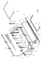
- the spoiler 1 has two axle support devices 10, one on each side.
- the axle support devices 10 are made by punching and each of them has a projection 101.
- the projection 101 has two lateral cotter holes 102, 103 at both ends and a vertical recess 104 in the middle.
- a split cotter 11 is fitted in either cotter hole 102 or 1023.
- the split cotter 11 consists of a head 111 and a split end 110 which can snap in the cotter hole 102 or 103 after the head 110 is inserted. It can be removed from the hole 102 or 103 by pressing the two parts of the split end together.
- the spoiler 1 also has two supports 12 on the inside near the corner for the lateral rod 211 of the canvas 6 of the packable car cover to rest.
- the lateral rod 211 has two rubber casings 212, 213 to increase friction with the supports 12 and to prevent it from falling off.
- the spoiler 1 has rubber packings 3, 4.
- the rubber packing 3 has a groove 30 for fitting on the edge 13 of the spoiler and the rubber packing 4 has a groove 40 for fitting on the edge 140 of the cover 14.
- the spoiler 1 and the lid 14 are joined together with three hinges 15.
- the lid 14 has two hook retainers 16 to be inserted in the retainer holes 17 in the spoiler 1 and retained therein.
- the hook retainer 16 is fixed to a slide switch 17 and can be released by laterally pushing the slide switch 17.
- the spoiler 1 also has two holes 18 for draining away the water in the spoiler 1.
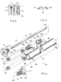
- the winder 33 of the packable car cover 2 consists of a spindle 36, two heads 34, 35, two springs 342, 352, one axle 20 and two cones 344, 354.
- the heads 34, 35 have stubs 340, 350 with spiral grooves 341, 351 for the springs 342, 352 to fit on, axle holes 343, 353 for the flat-ended axle 20 to fit in, and screw holes 349, 359 for fixing themselves to the spindle 36 by means of screws 360, 361.
- the cones 344, 354 have spiral grooves 348, 358 for the other ends of the springs 342, 352 to fit on, screw holes 346, 356 for fixing themselves to the axle 20 by means of screws 345, 355, and axle holes for the axle 20 to fit in.
- the spindle 36 has screw holes 362 for the screws 360, 361 to fix the heads 34, 35. To assemble, one of the two heads 34, 35 may be fixed at last. Guided by the heads 34, 35 of the winder 33, the combination 37 of canvas 6 and frame 5 is wound on the spindle 36 and the lateral rod 211 at the front end is placed on the supports 12. Since the flat ends 364, 365 of the axle 20 are fixed in the vertical recesses 104 of the support devices 10 as shown in Fig.
- the axle 20 will not turn with the unwinding of the combination 37 as it is pulled. Since the spindle 36 is fixed to the heads 34, 35, the springs 342, 352 will be forced out of shape when the spindle turns with the unwinding of the canvas 6. The springs 342, 352 will return to their original form when the spindle 36 turns with the winding of the canvas 6 as it is released.
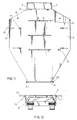
- the folding frame 5 consists of two side plates 50, 51, a bottom plate 503, a retaining plate 54, and two extension rods 52.
- the side plates 50, 51 have adjusting holes 500, 510, lateral slots 501, 511, and snap sinks 502, 512 around the adjusting holes 500, 510.
- the extension rods 52 has a bolt hold 520 at the end for a bolt 53 to fit in. After passing the adjusting hole 500, bolt hole 520, another adjusting hole 510, a washer 530, a spring 531 and another washer 532, the bolt 53 is screwed on by a nut 533 to hold the parts together.
- the bottom plate 503 has packing holes (not shown) and the retaining plate 54 has studs 540 so that the canvas 6 can be held firmly by the bottom plate 503 and retaining plate 54 after the studs 540 are inserted in the packing holes as shown in Fig. 10.
- the connection of the extension rod 52 and the canvas 6 is achieved by inserting the extension rod 52 in the receptacles made in the canvas 6.
- the joint of the side plates 50, 51 and the extension rod 52 is a three-step joint. When the extension rod 52 is pulled away, the head 534 of the bolt 53 will move from one sink 421 to another and the rod 52 can be folded.
- the canvas 6 has hook holes 60 (also as shown in Fig. 1) for the fastening hooks 16 of the spoiler 1 to insert to prevent the canvas 6 from being punctured by the hooks 16 and to prevent the user from being injured by the canvas 6 when it is rewound suddenly by the winder 33 (as shown in Fig. 4) after the hooks 214 at the lateral rod 211 slip off the car bottom edge.
- Reinforcements 61 are provided around the hook holes 60 as protection against fracture.
- the canvas 6 has hooks 62 at both sides for fastening the canvas 6 to the bottom edge of the car body to prevent the canvas 6 from being blown off by the wind.
- the hooks 62 are fastened to the canvas 6 by elastic bands 63 and can be attached to the strips 64 when not in use.
- the strips 64 are attached to the canvas 6 by sewing at both ends.
- adhesive tapes 65 are provided at the rear end of the canvas 6 to hold the side folds in place.
- the extension rod 52 of the frame 5 can be adjusted in three steps.
- the rod 52 is in a horizontal position 55 and, with greatest sunshade area, is suitable for use in a large place.
- the rod 52 is in an inclined position 56 and is suitable for use in a smaller place.
- the rod 52 is in a vertical position 57 and is suitable for use in a further smaller place.
- the frame 5 can be adjusted according to the direction of the sun. From the above it is clear that the packable car cover 2 consists of a winder, canvas and frame and can be adjusted in three steps, and used for protection against the sun's rays and dust. As shown in Figs.
- the reel of the roll of the disposable car cover 7 consists of a spindle 31 and two heads 320.
- Each of the heads 320 has a stub axle 32 and a stud 321.
- the stud 321 has ribs 322 to be held by the spindle 31.
- the round stub axle 32 is mounted in the vertical recess 104 of the support device 10 and retained by the cotter 11 and can turn with the unrolling of the roll of disposable car cover 7. So the roll of disposable car cover is suitable for use to protect against the rain and snow.
- the roll of disposable car cover 7 has three different types as follows:
- the adhesive type car cover roll 70 as shown in Figs. 14 and 15 has its left and right parts 702, 701 doubled up on itself and has adhesive strips 703 at the edge of each fold.
- the roll 70 also has rows of perforations 704 to facilitate tearing into separate covers 705.
- An adhesive strip 706 is also provided just before the separations 704 in order that the left and right parts 702, 701 can adhere to the bottom edge of the car head after being unfolded.
- the lid 14 of the spoil 1 can be closed so that the hook retainers 16 can insert in the separations 704 to facilitate separating and disposing after use.
- Figs. 16 and 17 show the first fastening band type car cover roll 71 which is used in the snowy day.
- This roll 71 has separations 710, 711 to facilitate tearing into separate covers 712.
- the cover 712 is folded up from the unfoldable side parts 713, 714.
- the side parts 713, 714 can cover the car sides after being unfolded.
- the cover 712 also have unfolded front and rear parts 715, 716 to cover the front and rear ends of the car body after being unfolded.
- the side parts 713, 714 have separations 717 to facilitate the separating of the end of the fastening band.
- the front and rear parts 715, 716 and the fastening bands 718 have fastening holes 719 for fastening the cover 712 to the hooks attached to the car bottom to prevent the cover 712 from being blown away by the wind.
- Figs. 18 and 19 show the second band type car cover roll 72 which is used in the slightly snowy day. It also has separations 720, 721 to facilitate tearing into separate covers 722.
- the cover 722 is made in contingent on the length of the car body and has unfoldable fastening bands 724, 725 and fastening holes 726 in the front part and fastening bands for attaching the cover 722 to the car bottom hooks after being unfolded.
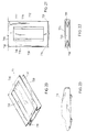
- Figs. 20, 21, 22 and 23 show the bag type car cover roll 73 which is used in the snowy and rainy day.
- the roll 73 has separations 730, 731 to facilitate tearing into separate covers 732, and seal lines 733, 734 to form a container after being separated.
- the cover 732 has a pleated expansible parts 738, 739 at both sides and an oblong opening 736 in the bottom part 735 so that the whole car body can be wrapped in the cover 732 as shown in Fig. 23 without fear of being blown away by the wind.
Landscapes
- Engineering & Computer Science (AREA)
- Mechanical Engineering (AREA)
- Vehicle Interior And Exterior Ornaments, Soundproofing, And Insulation (AREA)
- Packaging Of Machine Parts And Wound Products (AREA)
- Window Of Vehicle (AREA)
- Tents Or Canopies (AREA)
- Fittings On The Vehicle Exterior For Carrying Loads, And Devices For Holding Or Mounting Articles (AREA)
- Body Structure For Vehicles (AREA)
Priority Applications (5)
| Application Number | Priority Date | Filing Date | Title |
|---|---|---|---|
| ES87112943T ES2021658B3 (es) | 1987-09-04 | 1987-09-04 | Un montaje para cubrir coches |
| AT87112943T ATE61976T1 (de) | 1987-09-04 | 1987-09-04 | Abdeckeinrichtung fuer fahrzeuge. |
| EP87112943A EP0305579B1 (de) | 1987-09-04 | 1987-09-04 | Abdeckeinrichtung für Fahrzeuge |
| DE8787112943T DE3768957D1 (de) | 1987-09-04 | 1987-09-04 | Abdeckeinrichtung fuer fahrzeuge. |
| GR91400868T GR3002182T3 (en) | 1987-09-04 | 1991-06-25 | A car cover assembly |
Applications Claiming Priority (1)
| Application Number | Priority Date | Filing Date | Title |
|---|---|---|---|
| EP87112943A EP0305579B1 (de) | 1987-09-04 | 1987-09-04 | Abdeckeinrichtung für Fahrzeuge |
Publications (2)
| Publication Number | Publication Date |
|---|---|
| EP0305579A1 true EP0305579A1 (de) | 1989-03-08 |
| EP0305579B1 EP0305579B1 (de) | 1991-03-27 |
Family
ID=8197258
Family Applications (1)
| Application Number | Title | Priority Date | Filing Date |
|---|---|---|---|
| EP87112943A Expired - Lifetime EP0305579B1 (de) | 1987-09-04 | 1987-09-04 | Abdeckeinrichtung für Fahrzeuge |
Country Status (5)
| Country | Link |
|---|---|
| EP (1) | EP0305579B1 (de) |
| AT (1) | ATE61976T1 (de) |
| DE (1) | DE3768957D1 (de) |
| ES (1) | ES2021658B3 (de) |
| GR (1) | GR3002182T3 (de) |
Cited By (5)
| Publication number | Priority date | Publication date | Assignee | Title |
|---|---|---|---|---|
| EP0386751A1 (de) * | 1989-03-10 | 1990-09-12 | Dieter Walter | Sonnenschutzvorrichtung für Kraftfahrzeuge |
| US5697664A (en) * | 1994-06-13 | 1997-12-16 | Chenowth; Lynn | Cover for open-topped container and tie-down system therefor |
| WO2015033071A1 (fr) | 2013-09-05 | 2015-03-12 | Royal Mathieu | Dispositif deployable de protection de vehicule automobile en stationnement |
| CN107776380A (zh) * | 2016-08-26 | 2018-03-09 | 深圳大行同宇科技有限公司 | 一种一次性防晒车衣装置及汽车 |
| CN112356646A (zh) * | 2020-11-22 | 2021-02-12 | 深圳大行同宇科技有限公司 | 一种简易的防晒车衣装置 |
Citations (1)
| Publication number | Priority date | Publication date | Assignee | Title |
|---|---|---|---|---|
| DE8618733U1 (de) * | 1986-07-12 | 1986-11-13 | Schneeweiß, Dieter, 8940 Memmingen | Kraftfahrzeug mit einem Sonnenschutzdach |
-
1987
- 1987-09-04 EP EP87112943A patent/EP0305579B1/de not_active Expired - Lifetime
- 1987-09-04 DE DE8787112943T patent/DE3768957D1/de not_active Expired - Fee Related
- 1987-09-04 ES ES87112943T patent/ES2021658B3/es not_active Expired - Lifetime
- 1987-09-04 AT AT87112943T patent/ATE61976T1/de active
-
1991
- 1991-06-25 GR GR91400868T patent/GR3002182T3/el unknown
Patent Citations (1)
| Publication number | Priority date | Publication date | Assignee | Title |
|---|---|---|---|---|
| DE8618733U1 (de) * | 1986-07-12 | 1986-11-13 | Schneeweiß, Dieter, 8940 Memmingen | Kraftfahrzeug mit einem Sonnenschutzdach |
Cited By (5)
| Publication number | Priority date | Publication date | Assignee | Title |
|---|---|---|---|---|
| EP0386751A1 (de) * | 1989-03-10 | 1990-09-12 | Dieter Walter | Sonnenschutzvorrichtung für Kraftfahrzeuge |
| US5697664A (en) * | 1994-06-13 | 1997-12-16 | Chenowth; Lynn | Cover for open-topped container and tie-down system therefor |
| WO2015033071A1 (fr) | 2013-09-05 | 2015-03-12 | Royal Mathieu | Dispositif deployable de protection de vehicule automobile en stationnement |
| CN107776380A (zh) * | 2016-08-26 | 2018-03-09 | 深圳大行同宇科技有限公司 | 一种一次性防晒车衣装置及汽车 |
| CN112356646A (zh) * | 2020-11-22 | 2021-02-12 | 深圳大行同宇科技有限公司 | 一种简易的防晒车衣装置 |
Also Published As
| Publication number | Publication date |
|---|---|
| DE3768957D1 (de) | 1991-05-02 |
| GR3002182T3 (en) | 1992-12-30 |
| ES2021658B3 (es) | 1991-11-16 |
| EP0305579B1 (de) | 1991-03-27 |
| ATE61976T1 (de) | 1991-04-15 |
Similar Documents
| Publication | Publication Date | Title |
|---|---|---|
| US5275460A (en) | Motor vehicle protective cover | |
| US6412851B1 (en) | Retractable cover for small vehicles | |
| EP0471868B1 (de) | Abdeckung für Kraftfahrzeuge | |
| US4657298A (en) | Vehicle protective cover device | |
| US4958881A (en) | Theft proof protective covering for parked vehicle | |
| US3563594A (en) | Retractable flexible car body protector | |
| US4929016A (en) | Bi-directional roof mounted car protective device | |
| US4955505A (en) | Trash receptacle lining system | |
| US5875904A (en) | Box-like transport container | |
| US5597196A (en) | Automobile cover deployment and storage system | |
| US5086988A (en) | Car cover deployment and storage system | |
| US4479677A (en) | Pickup truck tonneau cover | |
| US2961255A (en) | Trailer skirts | |
| US4732421A (en) | Self-storing, retractable automobile cover | |
| US5758704A (en) | Roll-up screen door apparatus | |
| US5314226A (en) | Vehicle sunshield | |
| US20040238089A1 (en) | Self coiling roll-up car cover | |
| EP0305579A1 (de) | Abdeckeinrichtung für Fahrzeuge | |
| US5584524A (en) | Liner for truck bed | |
| US20090289137A1 (en) | Portable collapsible apparatus for storing and dispensing paper towels | |
| WO1994025303A1 (en) | Portable car cover assembly | |
| US5810415A (en) | Method of unloading objects from a rear opening vehicle | |
| US4840497A (en) | Sunshades storage case | |
| US2712715A (en) | Tree cover or tent | |
| US20040188036A1 (en) | Self-mounting automobile window screen |
Legal Events
| Date | Code | Title | Description |
|---|---|---|---|
| PUAI | Public reference made under article 153(3) epc to a published international application that has entered the european phase |
Free format text: ORIGINAL CODE: 0009012 |
|
| AK | Designated contracting states |
Kind code of ref document: A1 Designated state(s): AT BE CH DE ES FR GB GR IT LI LU NL SE |
|
| 17P | Request for examination filed |
Effective date: 19890411 |
|
| 17Q | First examination report despatched |
Effective date: 19891219 |
|
| GRAA | (expected) grant |
Free format text: ORIGINAL CODE: 0009210 |
|
| AK | Designated contracting states |
Kind code of ref document: B1 Designated state(s): AT BE CH DE ES FR GB GR IT LI LU NL SE |
|
| REF | Corresponds to: |
Ref document number: 61976 Country of ref document: AT Date of ref document: 19910415 Kind code of ref document: T |
|
| ET | Fr: translation filed | ||
| ITF | It: translation for a ep patent filed | ||
| REF | Corresponds to: |
Ref document number: 3768957 Country of ref document: DE Date of ref document: 19910502 |
|
| PGFP | Annual fee paid to national office [announced via postgrant information from national office to epo] |
Ref country code: CH Payment date: 19910727 Year of fee payment: 5 |
|
| PGFP | Annual fee paid to national office [announced via postgrant information from national office to epo] |
Ref country code: FR Payment date: 19910731 Year of fee payment: 5 |
|
| PGFP | Annual fee paid to national office [announced via postgrant information from national office to epo] |
Ref country code: GB Payment date: 19910805 Year of fee payment: 5 |
|
| PGFP | Annual fee paid to national office [announced via postgrant information from national office to epo] |
Ref country code: AT Payment date: 19910812 Year of fee payment: 5 |
|
| PGFP | Annual fee paid to national office [announced via postgrant information from national office to epo] |
Ref country code: LU Payment date: 19910814 Year of fee payment: 5 |
|
| PGFP | Annual fee paid to national office [announced via postgrant information from national office to epo] |
Ref country code: DE Payment date: 19910820 Year of fee payment: 5 |
|
| PGFP | Annual fee paid to national office [announced via postgrant information from national office to epo] |
Ref country code: SE Payment date: 19910830 Year of fee payment: 5 Ref country code: GR Payment date: 19910830 Year of fee payment: 5 |
|
| PGFP | Annual fee paid to national office [announced via postgrant information from national office to epo] |
Ref country code: BE Payment date: 19910905 Year of fee payment: 5 |
|
| PGFP | Annual fee paid to national office [announced via postgrant information from national office to epo] |
Ref country code: ES Payment date: 19910912 Year of fee payment: 5 |
|
| PGFP | Annual fee paid to national office [announced via postgrant information from national office to epo] |
Ref country code: NL Payment date: 19910930 Year of fee payment: 5 |
|
| EPTA | Lu: last paid annual fee | ||
| PLBE | No opposition filed within time limit |
Free format text: ORIGINAL CODE: 0009261 |
|
| STAA | Information on the status of an ep patent application or granted ep patent |
Free format text: STATUS: NO OPPOSITION FILED WITHIN TIME LIMIT |
|
| 26N | No opposition filed | ||
| REG | Reference to a national code |
Ref country code: GR Ref legal event code: FG4A Free format text: 3002182 |
|
| PG25 | Lapsed in a contracting state [announced via postgrant information from national office to epo] |
Ref country code: LU Free format text: LAPSE BECAUSE OF NON-PAYMENT OF DUE FEES Effective date: 19920904 Ref country code: GB Effective date: 19920904 Ref country code: AT Effective date: 19920904 |
|
| PG25 | Lapsed in a contracting state [announced via postgrant information from national office to epo] |
Ref country code: SE Effective date: 19920905 Ref country code: ES Free format text: LAPSE BECAUSE OF EXPIRATION OF PROTECTION Effective date: 19920905 |
|
| PG25 | Lapsed in a contracting state [announced via postgrant information from national office to epo] |
Ref country code: LI Effective date: 19920930 Ref country code: CH Effective date: 19920930 Ref country code: BE Effective date: 19920930 |
|
| BERE | Be: lapsed |
Owner name: SU YUNG-FR Effective date: 19920930 |
|
| PG25 | Lapsed in a contracting state [announced via postgrant information from national office to epo] |
Ref country code: GR Free format text: THE PATENT HAS BEEN ANNULLED BY A DECISION OF A NATIONAL AUTHORITY Effective date: 19930331 |
|
| PG25 | Lapsed in a contracting state [announced via postgrant information from national office to epo] |
Ref country code: NL Effective date: 19930401 |
|
| GBPC | Gb: european patent ceased through non-payment of renewal fee |
Effective date: 19920904 |
|
| NLV4 | Nl: lapsed or anulled due to non-payment of the annual fee | ||
| PG25 | Lapsed in a contracting state [announced via postgrant information from national office to epo] |
Ref country code: FR Effective date: 19930528 |
|
| REG | Reference to a national code |
Ref country code: CH Ref legal event code: PL |
|
| PG25 | Lapsed in a contracting state [announced via postgrant information from national office to epo] |
Ref country code: DE Effective date: 19930602 |
|
| REG | Reference to a national code |
Ref country code: FR Ref legal event code: ST |
|
| REG | Reference to a national code |
Ref country code: GR Ref legal event code: MM2A Free format text: 3002182 |
|
| EUG | Se: european patent has lapsed |
Ref document number: 87112943.3 Effective date: 19930406 |
|
| REG | Reference to a national code |
Ref country code: ES Ref legal event code: FD2A Effective date: 19990601 |
|
| PG25 | Lapsed in a contracting state [announced via postgrant information from national office to epo] |
Ref country code: IT Free format text: LAPSE BECAUSE OF NON-PAYMENT OF DUE FEES;WARNING: LAPSES OF ITALIAN PATENTS WITH EFFECTIVE DATE BEFORE 2007 MAY HAVE OCCURRED AT ANY TIME BEFORE 2007. THE CORRECT EFFECTIVE DATE MAY BE DIFFERENT FROM THE ONE RECORDED. Effective date: 20050904 |