EP0305628A1 - Pistenbearbeitungsgerät für Pistenfahrzeuge - Google Patents
Pistenbearbeitungsgerät für Pistenfahrzeuge Download PDFInfo
- Publication number
- EP0305628A1 EP0305628A1 EP87890202A EP87890202A EP0305628A1 EP 0305628 A1 EP0305628 A1 EP 0305628A1 EP 87890202 A EP87890202 A EP 87890202A EP 87890202 A EP87890202 A EP 87890202A EP 0305628 A1 EP0305628 A1 EP 0305628A1
- Authority
- EP
- European Patent Office
- Prior art keywords
- snow
- extensions
- elastic part
- smoothing
- working device
- Prior art date
- Legal status (The legal status is an assumption and is not a legal conclusion. Google has not performed a legal analysis and makes no representation as to the accuracy of the status listed.)
- Granted
Links
- 238000009499 grossing Methods 0.000 claims abstract description 13
- 239000011324 bead Substances 0.000 claims description 4
- 238000005056 compaction Methods 0.000 claims description 2
- 238000003801 milling Methods 0.000 claims description 2
- 230000003370 grooming effect Effects 0.000 claims 1
- 230000006835 compression Effects 0.000 description 2
- 238000007906 compression Methods 0.000 description 2
- 238000004519 manufacturing process Methods 0.000 description 2
Images
Classifications
-
- E—FIXED CONSTRUCTIONS
- E01—CONSTRUCTION OF ROADS, RAILWAYS, OR BRIDGES
- E01H—STREET CLEANING; CLEANING OF PERMANENT WAYS; CLEANING BEACHES; DISPERSING OR PREVENTING FOG IN GENERAL CLEANING STREET OR RAILWAY FURNITURE OR TUNNEL WALLS
- E01H4/00—Working on surfaces of snow or ice in order to make them suitable for traffic or sporting purposes, e.g. by compacting snow
- E01H4/02—Working on surfaces of snow or ice in order to make them suitable for traffic or sporting purposes, e.g. by compacting snow for sporting purposes, e.g. preparation of ski trails; Construction of artificial surfacings for snow or ice sports ; Trails specially adapted for on-the-snow vehicles, e.g. devices adapted for ski-trails
Definitions
- the invention relates to a slope processing device for snow groomers with a cross frame of the extensions, for receiving a smoothing device from the snow groomer, which has a flexible part for compaction and smoothing of the slope leveled by a milling machine of the snow groomer.
- the object of the present invention is to eliminate this disadvantage and to produce a piste processing device to be traced by the snow groomer, which is simple to manufacture, offers sufficient support on the cross frame of the vehicle and requires simple tools for the manufacture.
- the smoothing device in the form of a plate-shaped, on its bottom side rows of beads having elastic parts directly between the extensions of the cross frame of the snow groomer e.g. is connected by screw.
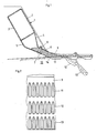
- 1 denotes the transverse frame, which has a rectangular box shape in cross section and has at its end facing the floor in extension of its side walls 2, 3 extensions 4 and 5, the arms 6 and 6, which are spaced apart and parallel to one another 7 leak, between which a preferably made of plastic elastic plate 9 is fastened by means of screw 8, which in the unloaded state, as shown in broken lines, is directed obliquely downwards in the direction of the arms 6, 7 against the slope bottom 10 while it is running in the loaded state, ie when pulling over the surface of the slope is bent into a horizontal position represented by solid lines.
- On the bottom surface of the plate 9 3 rows 11, 12, 13 of beads are arranged, which are located transversely to the direction of travel.
- the arm 7 of the frame 1 directed obliquely to the ground serves to compact the snow mass lying on the ground of the runway. This compression surface is continued by a part of the bottom surface of the plate 9 and the end faces 14 of the beads 11 located in the direction of travel.
Landscapes
- Engineering & Computer Science (AREA)
- Architecture (AREA)
- Civil Engineering (AREA)
- Structural Engineering (AREA)
- Harvester Elements (AREA)
- Road Paving Structures (AREA)
- Cleaning Of Streets, Tracks, Or Beaches (AREA)
- Platform Screen Doors And Railroad Systems (AREA)
- Soil Working Implements (AREA)
- Pit Excavations, Shoring, Fill Or Stabilisation Of Slopes (AREA)
Abstract
Description
- Die Erfindung betrifft ein Pistenbearbeitungsgerät für Pistenfahrzeuge mit einem Querrahmen der Fortsätze, zur Aufnahme einer vom Pistenfahrzeug nachziehenden Glätteinrichtung aufweist, welche einen nach giebigen Teil zur Verdichtung und Glättung der durch eine Fräse des Pistenfahrzeuges geebneten Piste besitzt.
- Durch die europ. Patentanmeldung Nr. 211.380 ist ein Pistenfahrzeug mit einer Glätteinrichtung bekanntgeworden, welche mit einem vorderen im Querschnitt dreiecksartigen Teil an den Querrahmen des Fahrzeuges angeschlossen ist, wobei der Rahmen Fortsätze aufweist, in welche der dreiecksartige Teil seitlich eingeschoben ist. Das rückwärtige Ende des dreiecksartigen Teiles setzt sich in einem nachgiebigen Teil fort, welcher bodenseitig querein wulstförmige Rippen trägt, durch welche die Piste geebnet wird. Außerdem ist die Brust- seite des dreiecksartigen Teiles als starre Verdichtungsfläche ausgebildet. Pistenfahrzeuge dieser Art haben den Nachteil, daß der dreiecksartige Teil, welcher vorwiegend aus Kunststoff besteht, nur unter Anwendung von komplizierter Formen herstellbar ist und außerdem eine mangelnde Stabilität der Glätteinrichtung zur Folge hat.
- Aufgabe der vorliegenden Erfindung ist die Beseitigung dieses Nachteiles und die Herstellung eines vom Pistenfahrzeug nachzuziehenden Pistenbearbeitungs- gerätes, welches einfach in der Herstellung ist, eine ausreichende Abstützung am Querrahmen des Fahrzeuges bietet und zur Herstellung einfache Werkzeuge benötigt.
- Diese Aufgabe wird erfindungsgemäß dadurch gelöst, daß die Glätteinrichtung in Form eines plattenförmigen, an seiner Bodenseite Wulstreihen aufweisenden elastischen Teiles unmittelbar zwischen den Fortsätzen des Querrahmens des Pistenfahrzeuges z.B. durch Verschraubung verbunden ist.
- Weitere Einzelheiten der Erfindung werden an Hand der Zeichnung näher erläutert, in welcher.
- Fig. 1 eine Querschnitt des Querrahmens mit der daran anschließenden Glätteinrichtung und
- Fig. 2 die Glätteinrichtung in Druntersicht darstellt.
- In der Zeichnung ist mit 1 der Querrahmen bezeichnet, welcher im Querschnitt rechteckige Kastenform besitzt und an seinem dem Boden zugekehrten Ende in Verlängerung seiner Seitenwände 2, 3 Fortsätze 4 bzw. 5 aufweist die in zwei im Abstand voneinander liegende, parallel zueinander verlaufende Arme 6 und 7 auslaufen, zwischen denen mittels Schraube 8 eine vorzugsweise aus Kunststoff bestehende elastische Platte 9 befestigt ist, welche im unbelasteten Zustand, wie strichliert dargestellt, im wesentlichen in der Richtung der Arme 6, 7 gegen den Pistenboden 10 schräg nach unten gerichtet ist, während sie im belasteten Zustand, d.h. beim Nachziehen über die Pistenoberfläche in eine, durch volle Linien dargestellte, horizontale Lage gebogen wird. Auf der Bodenfläche der Platte 9 sind 3 Reihen 11, 12,13 von Wülsten angeordnet, die quer zur Fahrtrichtung gelegen sind. Der schräg zum Boden gerichtete Arm 7 des Rahmens 1 dient zur Verdichtung der am Boden der Piste liegenden Schneemasse. Diese Verdichtungsfläche wird durch einen Teil der Bodenfläche der Platte 9 und die in der Fahrtrichtung gelegenen Stirnseiten 14 der Wülste 11 fortgesetzt.
Claims (4)
Priority Applications (5)
| Application Number | Priority Date | Filing Date | Title |
|---|---|---|---|
| DE8787890202T DE3766108D1 (de) | 1987-09-03 | 1987-09-03 | Pistenbearbeitungsgeraet fuer pistenfahrzeuge. |
| AT87890202T ATE58194T1 (de) | 1987-09-03 | 1987-09-03 | Pistenbearbeitungsgeraet fuer pistenfahrzeuge. |
| ES87890202T ES2018854B3 (es) | 1987-09-03 | 1987-09-03 | Aparato para alisar pistas por vehiculos deslizadores |
| EP87890202A EP0305628B1 (de) | 1987-09-03 | 1987-09-03 | Pistenbearbeitungsgerät für Pistenfahrzeuge |
| GR90400887T GR3002514T3 (en) | 1987-09-03 | 1990-11-08 | Ski track working device for snow-grooming vehicles |
Applications Claiming Priority (1)
| Application Number | Priority Date | Filing Date | Title |
|---|---|---|---|
| EP87890202A EP0305628B1 (de) | 1987-09-03 | 1987-09-03 | Pistenbearbeitungsgerät für Pistenfahrzeuge |
Publications (2)
| Publication Number | Publication Date |
|---|---|
| EP0305628A1 true EP0305628A1 (de) | 1989-03-08 |
| EP0305628B1 EP0305628B1 (de) | 1990-11-07 |
Family
ID=8198528
Family Applications (1)
| Application Number | Title | Priority Date | Filing Date |
|---|---|---|---|
| EP87890202A Expired - Lifetime EP0305628B1 (de) | 1987-09-03 | 1987-09-03 | Pistenbearbeitungsgerät für Pistenfahrzeuge |
Country Status (5)
| Country | Link |
|---|---|
| EP (1) | EP0305628B1 (de) |
| AT (1) | ATE58194T1 (de) |
| DE (1) | DE3766108D1 (de) |
| ES (1) | ES2018854B3 (de) |
| GR (1) | GR3002514T3 (de) |
Citations (3)
| Publication number | Priority date | Publication date | Assignee | Title |
|---|---|---|---|---|
| EP0211380A2 (de) * | 1985-08-07 | 1987-02-25 | Karl Kässbohrer Fahrzeugwerke GmbH | Pistenfahrzeug mit höhenverstellbarer Bodenbearbeitungs-, insbesondere Schneefräsvorrichtung |
| US4651451A (en) * | 1985-02-07 | 1987-03-24 | Logan Manufacturing Company | Lightweight snow compactor for ski runs |
| US4651450A (en) * | 1984-04-11 | 1987-03-24 | Fallline Corporation | Packer bar assembly |
-
1987
- 1987-09-03 DE DE8787890202T patent/DE3766108D1/de not_active Expired - Fee Related
- 1987-09-03 EP EP87890202A patent/EP0305628B1/de not_active Expired - Lifetime
- 1987-09-03 ES ES87890202T patent/ES2018854B3/es not_active Expired - Lifetime
- 1987-09-03 AT AT87890202T patent/ATE58194T1/de active
-
1990
- 1990-11-08 GR GR90400887T patent/GR3002514T3/el unknown
Patent Citations (3)
| Publication number | Priority date | Publication date | Assignee | Title |
|---|---|---|---|---|
| US4651450A (en) * | 1984-04-11 | 1987-03-24 | Fallline Corporation | Packer bar assembly |
| US4651451A (en) * | 1985-02-07 | 1987-03-24 | Logan Manufacturing Company | Lightweight snow compactor for ski runs |
| EP0211380A2 (de) * | 1985-08-07 | 1987-02-25 | Karl Kässbohrer Fahrzeugwerke GmbH | Pistenfahrzeug mit höhenverstellbarer Bodenbearbeitungs-, insbesondere Schneefräsvorrichtung |
Also Published As
| Publication number | Publication date |
|---|---|
| EP0305628B1 (de) | 1990-11-07 |
| ES2018854B3 (es) | 1991-05-16 |
| GR3002514T3 (en) | 1993-01-25 |
| ATE58194T1 (de) | 1990-11-15 |
| DE3766108D1 (de) | 1990-12-13 |
Similar Documents
| Publication | Publication Date | Title |
|---|---|---|
| DE3903482A1 (de) | Frontladerfraesvorrichtung zum abfraesen von beschaedigten strassendecken | |
| CH651607A5 (en) | Trailer for snow vehicles, in particular for piste care | |
| DE2616055B2 (de) | Vorrichtung zum Schleifen von Eisenbahnschienen | |
| DE3124083A1 (de) | Zweiraedriger wagen zum trainieren von trabern | |
| EP0211380B1 (de) | Pistenfahrzeug mit höhenverstellbarer Bodenbearbeitungs-, insbesondere Schneefräsvorrichtung | |
| DE2927214A1 (de) | Vorrichtung zur erzeugung akustischer transversalwellen im erdboden | |
| DE2307660A1 (de) | Verbundgeraet zum gleichzeitigen planieren und verdichten des bodens | |
| EP0305628B1 (de) | Pistenbearbeitungsgerät für Pistenfahrzeuge | |
| DE3439590C2 (de) | Verteilmaschine zum Ausbringen von insbesondere körnigem Material | |
| DE202018101438U1 (de) | Gerät für die Pflege von Reitböden | |
| DE1924269A1 (de) | Arbeitsmaschine,insbesondere Frontlader fuer landwirtschaftliche Fahrzeuge | |
| DE102009049900B4 (de) | Geschlepptes Pistenbearbeitungsgerät | |
| DE4340612C1 (de) | Vorrichtung zum Umsetzen von Kompostmieten | |
| DE2401830A1 (de) | Kupplungs-aufbau fuer zugwagen mit sattelauflieger | |
| DE69924947T2 (de) | Batterietragestruktur für Schneeräumgeräte | |
| DE2023272C3 (de) | Einrichtung zum Präparieren von Schneepisten | |
| DE1090497B (de) | Vorrichtung zum Reinigen und Sortieren von landwirtschaftlichen Erzeugnissen, insbesondere von Getreide | |
| DE4411464C2 (de) | Vorrichtung zur Schienenreinigung bei Spiel- oder Modelleisenbahnen | |
| AT287563B (de) | Vorrichtung zum Fertigen von Treppenstufen | |
| CH582281A5 (en) | Road sweeping machine with rotating brush - has parallelogram lever system for lateral parallel movement of rotating brush | |
| DE4235446A1 (de) | Gerät zur Pflege von Tennisplätzen | |
| CH667680A5 (de) | Vorrichtung zum spuren und/oder planieren von langlaufloipen. | |
| DE1709507C2 (de) | Fahrbare Maschine zum Profilieren der Schotterbettung von Gleisen | |
| DE1708649A1 (de) | Verfahren und Vorrichtung zum Ausrichten eines Gleises der Seite nach | |
| DE3400702A1 (de) | Gleiskettenglied fuer kettenfahrzeuge |
Legal Events
| Date | Code | Title | Description |
|---|---|---|---|
| PUAI | Public reference made under article 153(3) epc to a published international application that has entered the european phase |
Free format text: ORIGINAL CODE: 0009012 |
|
| AK | Designated contracting states |
Kind code of ref document: A1 Designated state(s): AT BE CH DE ES FR GB GR IT LI LU NL SE |
|
| 17P | Request for examination filed |
Effective date: 19890629 |
|
| 17Q | First examination report despatched |
Effective date: 19890901 |
|
| RAP1 | Party data changed (applicant data changed or rights of an application transferred) |
Owner name: SGP VERKEHRSTECHNIK GESELLSCHAFT M.B.H. |
|
| GRAA | (expected) grant |
Free format text: ORIGINAL CODE: 0009210 |
|
| RAP1 | Party data changed (applicant data changed or rights of an application transferred) |
Owner name: MASCHINENFABRIK LIEZEN GESELLSCHAFT M.B.H. |
|
| AK | Designated contracting states |
Kind code of ref document: B1 Designated state(s): AT BE CH DE ES FR GB GR IT LI LU NL SE |
|
| REF | Corresponds to: |
Ref document number: 58194 Country of ref document: AT Date of ref document: 19901115 Kind code of ref document: T |
|
| REF | Corresponds to: |
Ref document number: 3766108 Country of ref document: DE Date of ref document: 19901213 |
|
| ET | Fr: translation filed | ||
| ITF | It: translation for a ep patent filed | ||
| GBT | Gb: translation of ep patent filed (gb section 77(6)(a)/1977) | ||
| PGFP | Annual fee paid to national office [announced via postgrant information from national office to epo] |
Ref country code: FR Payment date: 19910814 Year of fee payment: 5 |
|
| PGFP | Annual fee paid to national office [announced via postgrant information from national office to epo] |
Ref country code: GB Payment date: 19910816 Year of fee payment: 5 Ref country code: DE Payment date: 19910816 Year of fee payment: 5 |
|
| PGFP | Annual fee paid to national office [announced via postgrant information from national office to epo] |
Ref country code: CH Payment date: 19910822 Year of fee payment: 5 |
|
| PGFP | Annual fee paid to national office [announced via postgrant information from national office to epo] |
Ref country code: SE Payment date: 19910823 Year of fee payment: 5 |
|
| PGFP | Annual fee paid to national office [announced via postgrant information from national office to epo] |
Ref country code: AT Payment date: 19910826 Year of fee payment: 5 |
|
| PGFP | Annual fee paid to national office [announced via postgrant information from national office to epo] |
Ref country code: GR Payment date: 19910827 Year of fee payment: 5 |
|
| PGFP | Annual fee paid to national office [announced via postgrant information from national office to epo] |
Ref country code: LU Payment date: 19910829 Year of fee payment: 5 |
|
| PLBE | No opposition filed within time limit |
Free format text: ORIGINAL CODE: 0009261 |
|
| STAA | Information on the status of an ep patent application or granted ep patent |
Free format text: STATUS: NO OPPOSITION FILED WITHIN TIME LIMIT |
|
| PGFP | Annual fee paid to national office [announced via postgrant information from national office to epo] |
Ref country code: ES Payment date: 19910918 Year of fee payment: 5 |
|
| ITTA | It: last paid annual fee | ||
| PGFP | Annual fee paid to national office [announced via postgrant information from national office to epo] |
Ref country code: NL Payment date: 19910930 Year of fee payment: 5 |
|
| PGFP | Annual fee paid to national office [announced via postgrant information from national office to epo] |
Ref country code: BE Payment date: 19911015 Year of fee payment: 5 |
|
| 26N | No opposition filed | ||
| EPTA | Lu: last paid annual fee | ||
| PG25 | Lapsed in a contracting state [announced via postgrant information from national office to epo] |
Ref country code: LU Free format text: LAPSE BECAUSE OF NON-PAYMENT OF DUE FEES Effective date: 19920903 Ref country code: GB Effective date: 19920903 Ref country code: AT Effective date: 19920903 |
|
| PG25 | Lapsed in a contracting state [announced via postgrant information from national office to epo] |
Ref country code: SE Effective date: 19920904 Ref country code: ES Free format text: LAPSE BECAUSE OF THE APPLICANT RENOUNCES Effective date: 19920904 |
|
| PG25 | Lapsed in a contracting state [announced via postgrant information from national office to epo] |
Ref country code: LI Effective date: 19920930 Ref country code: CH Effective date: 19920930 Ref country code: BE Effective date: 19920930 |
|
| REG | Reference to a national code |
Ref country code: GR Ref legal event code: FG4A Free format text: 3002514 |
|
| BERE | Be: lapsed |
Owner name: MASCHINENFABRIK LIEZEN G.M.B.H. Effective date: 19920930 |
|
| PG25 | Lapsed in a contracting state [announced via postgrant information from national office to epo] |
Ref country code: GR Free format text: THE PATENT HAS BEEN ANNULLED BY A DECISION OF A NATIONAL AUTHORITY Effective date: 19930331 |
|
| PG25 | Lapsed in a contracting state [announced via postgrant information from national office to epo] |
Ref country code: NL Effective date: 19930401 |
|
| GBPC | Gb: european patent ceased through non-payment of renewal fee |
Effective date: 19920903 |
|
| NLV4 | Nl: lapsed or anulled due to non-payment of the annual fee | ||
| PG25 | Lapsed in a contracting state [announced via postgrant information from national office to epo] |
Ref country code: FR Effective date: 19930528 |
|
| REG | Reference to a national code |
Ref country code: CH Ref legal event code: PL |
|
| PG25 | Lapsed in a contracting state [announced via postgrant information from national office to epo] |
Ref country code: DE Effective date: 19930602 |
|
| REG | Reference to a national code |
Ref country code: FR Ref legal event code: ST |
|
| REG | Reference to a national code |
Ref country code: GR Ref legal event code: MM2A Free format text: 3002514 |
|
| EUG | Se: european patent has lapsed |
Ref document number: 87890202.2 Effective date: 19930406 |
|
| REG | Reference to a national code |
Ref country code: ES Ref legal event code: FD2A Effective date: 19991007 |
|
| PG25 | Lapsed in a contracting state [announced via postgrant information from national office to epo] |
Ref country code: IT Free format text: LAPSE BECAUSE OF NON-PAYMENT OF DUE FEES;WARNING: LAPSES OF ITALIAN PATENTS WITH EFFECTIVE DATE BEFORE 2007 MAY HAVE OCCURRED AT ANY TIME BEFORE 2007. THE CORRECT EFFECTIVE DATE MAY BE DIFFERENT FROM THE ONE RECORDED. Effective date: 20050903 |