EP0305723A2 - Mauerdurchführung für Kabel, Leitungen, Rohre oder dgl - Google Patents
Mauerdurchführung für Kabel, Leitungen, Rohre oder dgl Download PDFInfo
- Publication number
- EP0305723A2 EP0305723A2 EP88111893A EP88111893A EP0305723A2 EP 0305723 A2 EP0305723 A2 EP 0305723A2 EP 88111893 A EP88111893 A EP 88111893A EP 88111893 A EP88111893 A EP 88111893A EP 0305723 A2 EP0305723 A2 EP 0305723A2
- Authority
- EP
- European Patent Office
- Prior art keywords
- wall
- inner tube
- tube
- breakthrough
- pipe
- Prior art date
- Legal status (The legal status is an assumption and is not a legal conclusion. Google has not performed a legal analysis and makes no representation as to the accuracy of the status listed.)
- Granted
Links
- 230000006835 compression Effects 0.000 claims abstract description 16
- 238000007906 compression Methods 0.000 claims abstract description 16
- 238000007789 sealing Methods 0.000 claims abstract description 15
- 150000001875 compounds Chemical class 0.000 claims abstract description 10
- 239000000565 sealant Substances 0.000 claims abstract description 4
- 238000009434 installation Methods 0.000 abstract description 8
- ONBQEOIKXPHGMB-VBSBHUPXSA-N 1-[2-[(2s,3r,4s,5r)-3,4-dihydroxy-5-(hydroxymethyl)oxolan-2-yl]oxy-4,6-dihydroxyphenyl]-3-(4-hydroxyphenyl)propan-1-one Chemical compound O[C@@H]1[C@H](O)[C@@H](CO)O[C@H]1OC1=CC(O)=CC(O)=C1C(=O)CCC1=CC=C(O)C=C1 ONBQEOIKXPHGMB-VBSBHUPXSA-N 0.000 description 4
- 229940126142 compound 16 Drugs 0.000 description 4
- 230000035515 penetration Effects 0.000 description 2
- 230000000694 effects Effects 0.000 description 1
- 238000010304 firing Methods 0.000 description 1
- 239000007787 solid Substances 0.000 description 1
Images


Classifications
-
- H—ELECTRICITY
- H02—GENERATION; CONVERSION OR DISTRIBUTION OF ELECTRIC POWER
- H02G—INSTALLATION OF ELECTRIC CABLES OR LINES, OR OF COMBINED OPTICAL AND ELECTRIC CABLES OR LINES
- H02G3/00—Installations of electric cables or lines or protective tubing therefor in or on buildings, equivalent structures or vehicles
- H02G3/22—Installations of cables or lines through walls, floors or ceilings, e.g. into buildings
Definitions
- the invention relates to a wall bushing for cables, lines, pipes or the like.
- a pipe that can be inserted into a wall breakthrough and with a wall cover plate arranged on the outside of the pipe in the form of a flange and with a sealant that can be pressed in the longitudinal direction of the bushing to seal the wall bushing against the wall breakthrough .
- Such wall bushings are used to form a gas and moisture seal between cables, lines, pipes, etc. and the outer wall of a building in a wall opening subsequently made, through which the cables, lines and pipes pass from the outside into the interior of the building will.
- a seal is not only required between the cables, lines and pipes against the pipe essentially forming the wall duct, but also a seal between the pipe and the building wall.
- the pipe In known wall penetrations, the pipe is equipped with two flanges, between which a sealing compound is provided on the circumference of the pipe.
- the pipe is inserted into the wall opening and the one in the annular space between the pipe and the wall duct tion mass is pressed together by pressing the two flanges against the inner and outer wall of the wall opening.
- Such a wall duct is known from DE 29 01 266.
- a flange is designed as an annular piston which is displaceable at least over part of the breakthrough length for pressing the sealing compound within the wall opening and a flange which is displaceable longitudinally on the pipe is guided non-rotatably on the pipe.
- the wall duct is inserted from the outside into the wall opening: so that the sealing compound is located in the annular space between the wall duct and the wall opening.
- the degree of compression of the sealing compound and thus the sealing effect of the wall duct depends on the force applied to the clamping nut.
- the tightness of this wall duct depends on the installation personnel, i.e. it is not always guaranteed that the wall duct is sealed with sufficient care.
- the object of the invention is therefore to create a wall duct, which is completely independent of the type of installation and the reliability of the installation personnel has consistently good tightness between the wall opening and wall duct.
- the tube is designed as a telescopic tube which is acted upon by a compression spring and has an outer and an inner tube, and at the free end of the inner tube fold-out gripping means for support on the inside of the wall opening provided and the compressible sealant is arranged between the wall end plate and the outside of the wall opening.
- the wall duct is pushed into the wall opening from the outside and, depending on the wall thickness, the inner tube of the telescopic tube is pulled out until the gripping means lie against the inside of the wall. Due to the compression spring between the inner and outer tube of the telescopic tube, both tubes are clamped so that the wall cover plate with the sealing compound lies absolutely tight against the outside of the wall. The contact pressure of the wall cover plate and thus the sealing compound therefore only depends on the tension of the compression spring and is completely independent of the installation personnel. Depending on the wall thickness of the wall opening, different wall penetrations can be provided.
- the invention provides that a shoulder for a lip seal and the compression spring and an upstand for the compression spring are provided at the inner end of the outer tube.
- the lip seal is used to seal the two telescopic tubes against the wall breakthrough.
- the invention provides that the gripping means are designed as spreading hooks, the ends of which are clamped in the assembled state between the end of the outer tube and the inner tube against the inner tube.
- the telescopic tube can thus first be inserted into the wall duct without difficulty and then the spreading hooks can be folded out and attached to the inner surface of the wall.
- a removable mounting cap with pressure lips for abutment against the spreading hooks the pressure lips acting on the spreading hooks by spreading them approximately at right angles in the sense of spreading them out.
- the mounting cap with the pressure lips is placed on the free end of the inner tube, so that the pressure lips rest against the spreading hook which is clamped to the inner tube with the tips clamped between the inner and outer tubes.
- centering projections are arranged on the circumference of the outer tube.
- the invention provides that an end cover is provided for attachment to the free end of the inner tube after assembly.
- This ring-shaped end cover has no functional meaning, but only serves as a wall end.
- the mounting cap and the firing cover are equipped with a bayonet lock for attachment to the free end of the inner tube. This configuration enables the mounting cap or the end cover to be put on and taken off particularly easily.
- the wall end plate is provided with a plurality of connecting pieces.
- the wall duct is also suitable for a plurality of cables, lines or the like. Unused connection pieces can be closed with the help of shrink caps or mechanical seals.
- a wall bushing 3 is inserted into a wall opening 1 of a wall 2.
- the wall duct 3 has an inner telescopic tube 4 and an outer telescopic tube 5, which fit into one another via a compression spring 6 others are slidably connected.
- At the end of the outer tube 5 there is a shoulder 7 for a lip seal 8 and for supporting the compression spring 6.
- An upstand 9 is provided at the end of the inner tube 4 for supporting the compression spring 6 on the opposite side.
- spreading hooks 10 which abut an inner wall 11 of the wall 2, are arranged. The spreading hooks 10 engage in the inner tube 4 via approximately right-angled bends 10a.
- an end cap 12 is placed on the free end of the inner tube 4 via a basonet closure 13.
- the outer telescopic tube 5 has outside the wall opening 1 on the circumference of a solid wall end plate 14, which is coated with a sealing compound 16 towards the outside wall 15.
- a pipe socket 17 of the outer pipe 5 projects beyond the wall cover plate 14 and a shrink tube 18 is applied to it.
- centering projections 19 are arranged on the circumference of the outer tube.
- a cable 20 is guided through the wall duct 3.
- the wall duct 3 is installed as follows:
- a mounting cap 21 is attached to the free end of the inner tube 4 instead of the end cover 12 via the bayonet lock 13.
- the mounting cap 21 has pressure lips 22 which, under the action of pressure, on the bends 10a of the expansion bracket ken 10 rest, the spreading hooks are clamped in the assembled state with their tips 23 between the outer telescopic tube 5 and the inner telescopic tube 4 so that they abut the inner tube 4.
- the wall 2 is pierced from the inner wall 11, so that the wall opening 1 is formed. From the outside of the wall 15, the wall duct 3 is now inserted into the wall opening 1 by a single fitter until the sealing compound 16 abuts the outside of the wall 15. A stamp 24 is then inserted into the telescopic tube 4, 5. The punch 24 is pressed against the mounting cap 21 so that the inner tube 4 slides out of the outer tube 5. The tips 23 of the spreading hooks 10 slide out of the anchorage between the outer tube 5 and the inner tube 4. As soon as the inner tube 4 breaks through the wall breakthrough 1 on the inner wall 11, the spreading hooks 10 are pivoted radially outward by the pressure lips 22 of the mounting cap 21 abutting the bends 10a.
- the inner tube 4 is pulled back into the outer tube 5 by the force of the compression spring 6 until the spreading hooks 10 bear against the inner wall 11 of the wall 2.
- the two pipes 4 and 5 are braced against one another and the sealing compound 16 is pressed between the outside wall 15 and the wall end plate 14. There is thus a tight seal between the wall opening 1 and the wall duct 3.
- the contact pressure on the sealing compound 16 depends only on the compression spring 6 and is completely independent of the installation personnel. Depending on the wall thickness of the wall opening 1, different compression spring sizes and pipe lengths are provided.
- the mounting cap 21 is removed from the inner tube via the bayonet catch 13 and the cable 20 can be passed through the wall duct 3.
- the shrink tube 18 is shrunk onto the pipe socket 17.
- the annular end cover 12 can then be fastened to the end of the inner tube 4 with the aid of the bayonet catch 13.
- the wall end plate 14 can be equipped with several pipe sockets 17 and the end cover 12 with several openings. Sockets 17 that are not required can be closed with the aid of shrink caps or mechanical seals.
Landscapes
- Engineering & Computer Science (AREA)
- Architecture (AREA)
- Civil Engineering (AREA)
- Structural Engineering (AREA)
- Installation Of Indoor Wiring (AREA)
- Laying Of Electric Cables Or Lines Outside (AREA)
- Duct Arrangements (AREA)
- Details Of Indoor Wiring (AREA)
Abstract
Description
- Die Erfindung betrifft eine Mauerdurchführung für Kabel, Leitungen, Rohre oder dgl. mit einem in einen Mauerdurchbruch einsetzbaren Rohr und mit einer außen auf dem Rohr angeordneten Mauerabschlußplatte in Form eines Flansches sowie mit einer in Längsrichtung der Durchführung verpressbaren Dichtmasse zur Abdichtung der Mauerdurchführung gegenüber dem Mauerdurchbruch.
- Derartige Mauerdurchführungen dienen dazu, eine Gas- und Feuchtigkeitsabdichtung zwischen Kabeln, Leitungen, Rohren usw. und der Außenmauer eines Gebäudes in einem nachträglich in die Mauer eingebrachten Mauerdurchbruch zu bilden, durch den die Kabel, Leitungen und Rohre von außen in das Innere des Gebäudes hindurchgeführt werden. Dabei ist eine Abdichtung nicht nur zwischen den Kabeln, Leitungen und Rohren gegen das die Mauerdurchführung im wesentlichen bildende Rohr, sondern auch eine Abdichtung zwischen dem Rohr und der Gebäudemauer erforderlich.
- Bei bekannten Mauerdurchführungen ist das Rohr mit zwei Flanschen ausgerüstet, zwischen denen am Umfang des Rohres eine Dichtungsmasse vorgesehen ist. Das Rohr wird in den Mauerdurchbruch eingefügt und die sich im Ringraum zwischen dem Rohr und der Mauerdurchführung befindende Dich tungsmasse wird durch Anpressen der beiden Flansche an die Innen- und Außenwand des Mauerdurchbruches zusammengepreßt.
- Aus der DE 29 01 266 ist eine solche Mauerdurchführung bekannt. Dabei ist ein Flansch als zum Verpressen der Dichtungsmasse innerhalb des Mauerdurchbruches zumindest über einen Teil der Durchbruchlänge verschiebbarer Ringkolben fest am Rohr ausgebildet und ein auf dem Rohr längs verschiebbarer Flansch unverdrehbar am Rohr geführt. Die Mauerdurchführung wird von außen in den Mauerdurchbruch eingesetzt:, so daß sich die Dichtungsmasse im Ringraum zwischen der Mauerdurchführung und dem Mauerdurchbruch befindet. Durch Anziehen einer Spannmutter am längsverschiebbaren Flansch wird der als Ringkolben ausgebildete Flansch in die Mauerdurchführung hineingezogen, so daß sich die Dichtungsmasse verpreßt. Der Verpressungsgrad der Dichtmasse und damit die Dichtwirkung der Mauerdurchführung hängt von der auf die Spannmutter aufgebrachten Kraft ab. Damit ist die Dichtigkeit dieser Mauerdurchführung vom Montagepersonal abhängig, d.h. es ist nicht immer gewährleistet, daß die Mauerdurchführung ausreichend sorgfältig abgedichtet ist.
- Aufgabe der Erfindung ist deshalb die Schaffung einer Mauerdurchführung, welche völlig unabhängig von der Art der Montage und der Zuverlässigkeit des Montagepersonals eine gleichbleibend gute Dichtigkeit zwischen Mauerdurchbruch und Mauerdurchführung aufweist.
- Diese Aufgabe wird mit einer Mauerdurchführung der eingangs bezeichneten Art erfindungsgemäß dadurch gelöst, daß das Rohr als eine über eine Druckfeder beaufschlagtes Teleskoprohr mit einem äußeren und einem inneren Rohr ausgebildet ist, wobei am freien Ende des inneren Rohres ausklappbare Greifmittel zur Abstützung an der Innenseite des Mauerdurchbruches vorgesehen und zwischen der Mauerabschlußplatte und der Außenseite des Mauerdurchbruches die verpressbare Dichtmasse angeordnet ist.
- Die Mauerdurchführung wird von der Außenseite in den Mauerdurchbruch eingeschoben und entsprechend der Mauerstärke wird das innere Rohr des Teleskoprohres soweit ausgezogen bis die Greifmittel auf der Mauerinnenseite anliegen. Durch die Druckfeder zwischen dem inneren und äußeren Rohr des Teleskoprohres werden beide Rohre verspannt, so daß die Mauerabschlußplatte mit der Dichtmasse absolut dicht an der Maueraußenseite anliegt. Der Anpreßdruck der Mauerabschlußplatte und damit der Dichtmasse hängt demnach nur von der Spannung der Druckfeder ab und ist völlig unabhängig vom Montagepersonal. Je nach Mauerstärke des Mauerdurchbruches kann man unterschiedliche Mauerdurchführungen vorsehen.
- Weiterhin sieht die Erfindung vor, daß am inneren Ende des äußeren Rohres eine Schulter für eine Lippendichtung und die Druckfeder und am äußeren Ende des inneren Rohres eine Aufkantung für die Druckfeder vorgesehen sind. Die Lippendichtung dient dabei zur Abdichtung der beiden Teleskoprohre gegen den Mauerdurchbruch.
- Ferner sieht die Erfindung vor, daß die Greifmittel als Spreizhaken ausgebildet sind, deren Enden im Montagezustand zwischen dem Ende des äußeren Rohres und dem inneren Rohr am inneren Rohr anliegend eingeklemmt sind. Das Teleskoprohr kann somit zunächst ohne Schwierigkeiten in die Mauerdurchführung eingeführt werden und anschließern können die Spreizhaken ausgeklappt und an der Mauerinnenfläche befestigt werden.
- Außerdem ist vorgesehen, daß am freien Ende des inneren Rohres eine abnehmbare Montagekappe mit Drucklippen zur Anlage an den Spreizhaken vorgesehen ist, wobei die Drucklippen über etwa rechtwinklige Abbiegungen der Spreizhaken im Sinne einer Aufspreizung auf diese wirken. Vor der Montage wird die Montagekappe mit den Drucklippen auf das freie Ende des inneren Rohres aufgesetzt, so daß die Drucklippen an dem am inneren Rohr anliegenden mit den Spitzen zwischen dem inneren und äußeren Rohr eingeklemmten Spreizhaken anliegen. Nach Einführung der Mauerdurchführung in den Mauerdurchbruch wird mit Hilfe eines in das Rohr eingeführ ten Stempels die Montagekappe in das Innere der Mauerdurchführung eingedrückt, so daß gleichzeitig das innere Teleskoprohr ausgefahren wird und die Spreizhaken aus der Verankerung gelöst werden. Sobald das innere Rohr ausreichend weit aus der Mauerdurchführung herausragt, werden die Spreizhaken durch die Drucklippen der Montagekappe ausgeklappt und durch Rückführung des Stempels liegen die Spreizhaken an der Innenseite der Mauerdurchführung an, so daß das Rohr eingespannt ist. Diese Ausgestaltung ermöglicht die Montage der Mauerdurchführung durch eine Person von der Maueraußenseite.
- Zusätzlich kann vorgesehen sein, daß am Umfang des äußeren Rohres Zentriervorsprünge angeordnet sind.
- In weiterer Ausgestaltung sieht die Erfindung vor, daß ein Abschlußdeckel zum Aufsatz auf das freie Ende des inneren Rohres nach der Montage vorgesehen ist. Dieser ringförmige Abschlußdeckel hat keine funktionale Bedeutung, sondern dient nur als Mauerabschluß.
- In besonders vorteilhafter Ausgestaltung ist vorgesehen, daß die Montagekappe und der Abschußdeckel mit einem Bajonettverschluß zur Befestigung am freien Ende des inneren Rohres ausgerüstet ist. Diese Ausgestaltung ermöglicht ein besonders einfaches Auf- und Absetzen der Montagekappe bzw. des Abschlußdeckels.
- Schließlich ist vorgesehen, daß die Mauerabschlußplatte mit einer Mehrzahl von Anschlußstutzen versehen ist. Dadurch ist die Mauerdurchführung auch für eine Mehrzahl von Kabeln, Leitungen oder dgl. geeignet. Nicht benötigte Anschlußstutzen können dabei mit Hilfe von Schrumnpfkappen oder mechanischen Dichtungen verschlossen werden.
- Die Erfindung ist nachstehend anhand der Zeichnung beispielsweise näher erläutert. Diese zeigt in
- Fig. 1 in einem Längsschnitt ein Ausführungsbeispiel,
- Fig. 2 dasselbe Ausführungsbeispiel wie in Fig. 1 im Zustand vor der Montage,
- Fig. 3 ein Detail aus Fig. 2 vor der Montage,
- Fig. 4 dasselbe Detail wie in Fig. 3 nach der Montage und in
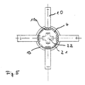
- Fig. 5 einem Schnitt gemäß der Linie V-V in Fig. 4.
- Wie in Fig. 1 dargestellt, ist in ein Mauerdurchbruch 1 einer Mauer 2 eine Mauerdurchführung 3 eingesetzt. Die Mauerdurchführung 3 weist ein inneres Teleskoprohr 4 und ein äußeres Teleskoprohr 5 auf, die über eine Druckfeder 6 inein ander verschiebbar verbunden sind. Am Ende des äußeren Rohres 5 befindet sich eine Schu]ter 7 für eine Lippendichtung 8 und zur Abstützung der Druckfeder 6. Zur Abstützung der Druckfeder 6 auf der Gegenseite ist am Ende des inneren Rohres 4 eine Aufkantung 9 vorgesehen. Am freien Ende des inneren Rohres 4 sind Spreizhaken 10, die an einer Innenwand 11 der Mauer 2 anliegen, angeordnet. Die Spreizhaken 10 greifer über etwa rechtwinklige Abbiegungen 10a in das innere Rohr 4 ein. Außerdem ist ein Abschlußdeckel 12 über einen Basonettverschluß 13 auf das freie Ende des inneren Rohres 4 gesetzt. Das äußere Teleskoprohr 5 weist außerhalb des Mauerdurchbruches 1 am Umfang eine feste Mauerabschlußplatte 14 auf, die zur Maueraußenseite 15 hin mit einer Dichtmasse 16 beschichtet ist. Über die Mauerabschlußplatte 14 hinaus ragt ein Rohrstutzen 17 des äußeren Rohres 5, auf den ein Schrumpfschlauch 18 aufgebracht ist. Zur Zentrierung des äußeren Rohres 5 sind am Umfang des äußeren Rohres 5 Zentriervorsprünge 19 angeordnet. Durch die Mauerdurchführung 3 ist ein Kabel 20 geführt.
- Die Mauerdurchführung 3 wird folgendermaßen montiert:
- Wie aus Fig. 2 ersichtlich, ist im Montagezustand am freien Ende des inneren Rohres 4 anstelle des Abschlußdeckels 12 eine Montagekappe 21 über den Bajonettverschluß 13 befestigt. Die Montagekappe 21 weist Drucklippen 22 auf, die unter Druckeinwirkung an den Abbiegungen l0a der Spreizha ken 10 anliegen, wobei die Spreizhaken im Montagezustand mit ihren Spitzen 23 zwischen dem äußeren Teleskoprohr 5 und dem inneren Teleskoprohr 4 eingeklemmt sind, so daß sie am inneren Rohr 4 anliegen.
- Von der Innenwand 11 aus wird die Mauer 2 durchbohrt, so daß der Mauerdurchbruch 1 entsteht. Von der Maueraußenseite 15 aus wird nun von einem einzigen Monteur die Mauerdurchführung 3 in den Mauerdurchbruch 1 eingeführt, bis die Dichtmasse 16 an der Maueraußenseite 15 anliegt. Anschließend wird ein Stempel 24 in das Teleskoprohr 4,5 eingeführt. Dabei wird der Stempel 24 gegen die Montagekappe 21 gedrückt, so daß das innere Rohr 4 aus dem äußeren Rohr 5 herausgleitet. Dabei rutschen die Spitzen 23 der Spreizhaken 10 aus der Verankerung zwischen dem äußeren Rohr 5 und dem inneren Rohr 4 heraus. Sobald das innere Rohr 4 den Mauerdurchbruch 1 auf der Innenwand 11 durchbricht, werden die Spreizhaken 10 durch die an den Abbiegungen 10a anliegenden Drucklippen 22 der Montagekappe 21 radial nach außen geschwenkt. Wird nun der Stempel 24 wieder herausgezogen, so wird das innere Rohr 4 durch die Kraft der Druckfeder 6 in das äußere Rohr 5 zurückgezogen, bis die Spreizhaken 10 an der Innenwand 11 der Mauer 2 anliegen. Dadurch werden die beiden Rohre 4 und 5 gegeneinander verspannt und die Dichtmasse 16 wird zwischen der Maueraußenseite 15 und der Mauerabschlußplatte 14 verpreßt. Es entsteht somit ein dichter Abschluß zwischen dem Mauerdurchbruch 1 und der Mauerdurchführung 3. Der Anpressdruck auf die Dichtmasse 16 hängt dabei nur von der Druckfeder 6 ab und ist völlig unabhängig vom Montagepersonal. Je nach Wandstärke des Mauerdurchbruchs 1 sind unterschiedliche Druckfedergrößen und Rohrlängen vorgesehen.
- Nach der Montage wird die Montagekappe 21 über den Bajonettverschluß 13 vom inneren Rohr abgenommen und das Kabel 20 kann durch die Mauerdurchfuhrung 3 hindurchgeführt werden. Zur Abdichtung des Kabels (20) an der Maueraußenseite 15 wird dabei der Schrumpfschlauch 18 auf den Rohrstutzen 17 aufgeschrumpft. Auf der Innenseite kann anschließend, wie in Fig. 1 dargestellt, der ringförmige Abschlußdeckel 12 mit Hilfe des Bajonettverschlusses 13 am Ende des inneren Rohres 4 befestigt werden.
- Zur Durchführung mehrerer Kabel 20 kann die Mauerabschlußplatte 14 mit mehreren Rohrstutzen 17 und der Abschlußdeckel 12 entsprechend mit mehreren Öffnungen ausgestattet sein. Nicht benötigte Stutzen 17 können mit Hilfe von Schrumpfkappen oder mechanischen Dichtungen verschlossen werden.
Claims (8)
dadurch gekennzeichnet,
daß das Rohr als über eine Druckfeder (6) beaufschlagtes Teleskoprohr mit einem äußeren (5) und einem inneren Rohr (4) ausgebildet ist, wobei am freien Ende des inneren Rohres (4) ausklappbare Greifmittel (10) zur Abstützung an der Innenseite (11) des Mauerdurchbruches (1) vorgesehen und zwischen der Mauerabschlußplatte (14) und der Außenseite (15) des Mauerdurchbruches (1) die verpressbare Dichtmasse (16) angeordnet ist.
dadurch gekennzeichnet,
daß am inneren Ende des äußeren Rohres (5) eine Schulter (7) für eine Lippendichtung (8) und die Druckfeder (6) und am äußeren Ende des inneren Rohres (4) eine Aufkantung (9) für die Druckfeder (6) vorgesehen sind.
dadurch gekennzeichnet,
daß die Greifmittel als Spreizhaken (10) ausgebildet sind, deren Enden (23) im Montagezustand zwischen dem inneren Ende des äußeren Rohres (5) und dem inneren Rohr (4) am inneren Rohr (4) anliegend eingeklemmt sind.
dadurch gekennzeichnet,
daß am freien Ende des inneren Rohres (4) eine abnehmbare Montagekappe (21) mit Drucklippen (22) zur Anlage an den Spreizhaken (10) vorgesehen ist, wobei die Drucklippen (22) über etwa rechtwinklige Abbiegungen (10a) der Spreizhaken (10) im Sinne einer Aufspreizung auf diese wirken.
dadurch gekennzeichnet,
daß am Umfang des äußeren Rohres (5) Zentriervorsprünge (19) angeordnet sind.
dadurch gekennzeichnet,
daß ein Abschlußdeckel (12) zum Aufsatz auf das freie Ende des inneren Rohres (4) nach der Montage vorgesehen ist.
dadurch gekennzeichnet,
daß die Montagekappe (21) und der Abschlußdeckel (12) mit einem Bajonettverschluß (13) zur Befestigung am freien Ende des inneren Rohres (4) ausgerüstet sind.
dadurch gekennzeichnet,
daß die Mauerabschlußplatte (14) mit einer Mehrzahl von Anschlußstutzen (17) versehen ist.
Priority Applications (1)
| Application Number | Priority Date | Filing Date | Title |
|---|---|---|---|
| AT88111893T ATE89956T1 (de) | 1987-09-04 | 1988-07-23 | Mauerdurchfuehrung fuer kabel, leitungen, rohre oder dgl. |
Applications Claiming Priority (2)
| Application Number | Priority Date | Filing Date | Title |
|---|---|---|---|
| DE19873729665 DE3729665A1 (de) | 1987-09-04 | 1987-09-04 | Mauerdurchfuehrung fuer kabel, leitungen, rohre oder dgl. |
| DE3729665 | 1987-09-04 |
Publications (3)
| Publication Number | Publication Date |
|---|---|
| EP0305723A2 true EP0305723A2 (de) | 1989-03-08 |
| EP0305723A3 EP0305723A3 (en) | 1990-09-26 |
| EP0305723B1 EP0305723B1 (de) | 1993-05-26 |
Family
ID=6335271
Family Applications (1)
| Application Number | Title | Priority Date | Filing Date |
|---|---|---|---|
| EP88111893A Expired - Lifetime EP0305723B1 (de) | 1987-09-04 | 1988-07-23 | Mauerdurchführung für Kabel, Leitungen, Rohre oder dgl |
Country Status (3)
| Country | Link |
|---|---|
| EP (1) | EP0305723B1 (de) |
| AT (1) | ATE89956T1 (de) |
| DE (2) | DE3729665A1 (de) |
Cited By (12)
| Publication number | Priority date | Publication date | Assignee | Title |
|---|---|---|---|---|
| EP0681134A1 (de) * | 1994-05-07 | 1995-11-08 | Werner Hauff | Vorrichtung zur Durchführung von Leitungen durch eine Wandöffnung |
| WO1996007227A1 (en) * | 1994-08-31 | 1996-03-07 | Miniflex Limited | Passing cables through walls |
| EP0790453A3 (de) * | 1996-02-19 | 1997-11-26 | Hauff-Technik GmbH & Co. KG | Dichtpackung zum Einsetzen in eine Maueröffnung zwecks Hindurchführens von Leitungen |
| RU2120692C1 (ru) * | 1996-06-13 | 1998-10-20 | Открытое акционерное общество "Ярославский электромашиностроительный завод" | Устройство для коммуникационного ввода-вывода |
| WO2005096054A1 (en) * | 2004-04-01 | 2005-10-13 | British Telecommunications Public Limited Company | Network termination apparatus |
| US6981989B1 (en) | 2003-04-22 | 2006-01-03 | X-Pantu-Flex Drd Limited Liability Company | Rotatable and reversibly expandable spinal hydraulic prosthetic device |
| RU2285854C2 (ru) * | 2005-01-11 | 2006-10-20 | Общество с ограниченной ответственностью "Переход" | Резиновая манжета для пропуска в защитной трубе кабеля связи и способ ее изготовления |
| US7419505B2 (en) | 2003-04-22 | 2008-09-02 | Fleischmann Lewis W | Collapsible, rotatable, and tiltable hydraulic spinal disc prosthesis system with selectable modular components |
| EP2003757A1 (de) * | 2007-06-15 | 2008-12-17 | Hauff-Technik GmbH & Co. KG | Erdleiterdurchführung |
| CN112762240A (zh) * | 2021-01-25 | 2021-05-07 | 浙江大亚节能科技有限公司 | 一种可拆卸的穿墙保温套及其安装方法 |
| CN112993913A (zh) * | 2021-04-25 | 2021-06-18 | 江苏世洲管业科技有限公司 | 一种高性能仿扭曲mpp电力电缆保护管及其制备方法 |
| CN117005711A (zh) * | 2023-06-30 | 2023-11-07 | 中国五冶集团有限公司 | 一种用于老旧建筑外立面更新的辅助钢管架 |
Families Citing this family (4)
| Publication number | Priority date | Publication date | Assignee | Title |
|---|---|---|---|---|
| DE8911802U1 (de) * | 1989-10-04 | 1989-11-16 | Walter Rose Gmbh & Co Kg, 5800 Hagen | Vorrichtung zur Durchführung von Kabeln durch Gebäudewände |
| DE3935531C1 (en) * | 1989-10-25 | 1990-11-29 | Walter Rose Gmbh & Co Kg, 5800 Hagen, De | Wall feed through for cable, leads, pipe, etc. - has spiral spring arranged coaxially to flexible hose axis |
| DE29517409U1 (de) * | 1995-11-03 | 1997-03-13 | DOYMA GmbH & Co., 28876 Oyten | Kabeldurchführung mit Schutzrohr |
| DE20017026U1 (de) * | 2000-10-04 | 2001-01-18 | Malzahn, Michael, 66440 Blieskastel | Dichtung zum Abdichten von Wandarmaturen |
Family Cites Families (4)
| Publication number | Priority date | Publication date | Assignee | Title |
|---|---|---|---|---|
| US3125358A (en) * | 1964-03-17 | Building lead-in connection for a pipe | ||
| GB1181651A (en) * | 1966-01-04 | 1970-02-18 | United Gas Industries Ltd | Improvements in or relating to Air Heaters |
| FR2287013A1 (fr) * | 1974-10-04 | 1976-04-30 | Saunier Duval | Dispositif d'etancheite des conduits d'amenee d'air frais et d'evacuation des gaz brules pour appareils du genre chaudiere etanche a gaz |
| DE3440512A1 (de) * | 1984-09-25 | 1986-04-10 | Armo Gesellschaft für Bauelemente, Bau- und Wohnbedarf mbH, 4350 Recklinghausen | Vorrichtung zum abdichten von wandungsoeffnungen oder kabel- und rohrdurchfuehrungen |
-
1987
- 1987-09-04 DE DE19873729665 patent/DE3729665A1/de not_active Withdrawn
-
1988
- 1988-07-23 AT AT88111893T patent/ATE89956T1/de not_active IP Right Cessation
- 1988-07-23 EP EP88111893A patent/EP0305723B1/de not_active Expired - Lifetime
- 1988-07-23 DE DE8888111893T patent/DE3881308D1/de not_active Expired - Fee Related
Cited By (16)
| Publication number | Priority date | Publication date | Assignee | Title |
|---|---|---|---|---|
| EP0681134A1 (de) * | 1994-05-07 | 1995-11-08 | Werner Hauff | Vorrichtung zur Durchführung von Leitungen durch eine Wandöffnung |
| WO1996007227A1 (en) * | 1994-08-31 | 1996-03-07 | Miniflex Limited | Passing cables through walls |
| GB2306796A (en) * | 1994-08-31 | 1997-05-07 | Miniflex Ltd | Passing cables through walls |
| GB2306796B (en) * | 1994-08-31 | 1998-04-08 | Miniflex Ltd | Passing cables through walls |
| EP0790453A3 (de) * | 1996-02-19 | 1997-11-26 | Hauff-Technik GmbH & Co. KG | Dichtpackung zum Einsetzen in eine Maueröffnung zwecks Hindurchführens von Leitungen |
| RU2120692C1 (ru) * | 1996-06-13 | 1998-10-20 | Открытое акционерное общество "Ярославский электромашиностроительный завод" | Устройство для коммуникационного ввода-вывода |
| US6981989B1 (en) | 2003-04-22 | 2006-01-03 | X-Pantu-Flex Drd Limited Liability Company | Rotatable and reversibly expandable spinal hydraulic prosthetic device |
| US7419505B2 (en) | 2003-04-22 | 2008-09-02 | Fleischmann Lewis W | Collapsible, rotatable, and tiltable hydraulic spinal disc prosthesis system with selectable modular components |
| US7599597B2 (en) | 2004-04-01 | 2009-10-06 | British Telecommunications Plc | Network termination apparatus |
| WO2005096054A1 (en) * | 2004-04-01 | 2005-10-13 | British Telecommunications Public Limited Company | Network termination apparatus |
| RU2285854C2 (ru) * | 2005-01-11 | 2006-10-20 | Общество с ограниченной ответственностью "Переход" | Резиновая манжета для пропуска в защитной трубе кабеля связи и способ ее изготовления |
| EP2003757A1 (de) * | 2007-06-15 | 2008-12-17 | Hauff-Technik GmbH & Co. KG | Erdleiterdurchführung |
| CN112762240A (zh) * | 2021-01-25 | 2021-05-07 | 浙江大亚节能科技有限公司 | 一种可拆卸的穿墙保温套及其安装方法 |
| CN112762240B (zh) * | 2021-01-25 | 2022-09-06 | 浙江大亚节能科技有限公司 | 一种可拆卸的穿墙保温套及其安装方法 |
| CN112993913A (zh) * | 2021-04-25 | 2021-06-18 | 江苏世洲管业科技有限公司 | 一种高性能仿扭曲mpp电力电缆保护管及其制备方法 |
| CN117005711A (zh) * | 2023-06-30 | 2023-11-07 | 中国五冶集团有限公司 | 一种用于老旧建筑外立面更新的辅助钢管架 |
Also Published As
| Publication number | Publication date |
|---|---|
| EP0305723A3 (en) | 1990-09-26 |
| DE3881308D1 (de) | 1993-07-01 |
| ATE89956T1 (de) | 1993-06-15 |
| EP0305723B1 (de) | 1993-05-26 |
| DE3729665A1 (de) | 1989-03-23 |
Similar Documents
| Publication | Publication Date | Title |
|---|---|---|
| EP0305723B1 (de) | Mauerdurchführung für Kabel, Leitungen, Rohre oder dgl | |
| DE19738733C1 (de) | Steckverbinder für Koaxialkabel mit ringgewelltem Außenleiter | |
| EP2270375A1 (de) | Brandschutzvorrichtung | |
| EP3292602B1 (de) | Kabel-/leitungseinführung | |
| EP3008370A1 (de) | Spann- oder rohrschelle | |
| DE202017107503U1 (de) | Führungsvorrichtung sowie Tülle | |
| WO2017055237A1 (de) | Leitungsdurchführung zum durchführen von leitungen durch ein bauteil | |
| EP1798459A1 (de) | Rohrverbindungsvorrichtung aus zwei halbschalenartigen Halteelementen | |
| DE4117932C2 (de) | ||
| DE2341814B2 (de) | Befestigungsvorrichtung | |
| EP0440903A1 (de) | Anpassungsdichtelement für den Abschluss einer Einführungsöffnung bei Kabelgarnituren, Rohrzügen oder dergleichen | |
| EP2565898B1 (de) | Elektrische Schaltanlage | |
| DE10349440B4 (de) | Dichte Wanddurchführung mit Zugentlastung | |
| EP0403937B1 (de) | Universalmuffe mit längsgeteiltem Muffenrohr und stirnseitigen Dichtungskörpern | |
| DE3130272A1 (de) | Vorrichtung zur festlegung einer rohrleitung | |
| DE3031687C2 (de) | Vorrichtung zum Schutz der Endbereiche von Rohren gegen mechanische Beschädigungen | |
| EP3544132A1 (de) | Axial fixierbare dichtungsanordnung für eine kabeldurchführung | |
| DE4223250A1 (de) | Automatisch montierbare Steckkupplung für Leitungsschläuche in Kraftfahrzeugen | |
| EP0290955A2 (de) | Einrichtung zum Abdichten von miteinander verbundenen Leitern von Kabeln | |
| EP0309836A2 (de) | Wasser- und gasdichte Mantelrohrdurchführung durch das Mauerwerk von Hauswänden und dergleichen | |
| DE102021103195B4 (de) | Verschlusshülse mit Klemmelement zum Abdichten einer Ankerspannstelle an einer Betonschalung | |
| EP0133455A2 (de) | Verschluss- oder Kupplungsvorrichtung | |
| DE8211691U1 (de) | Dichtungsmanschette aus elastischem Material für Wanddurchführungen | |
| DE10162813A1 (de) | Durchführungsdichtung | |
| EP4497983A1 (de) | Vorrichtung zur durchführung von mindestens einer leitung durch eine öffnung in einer wand |
Legal Events
| Date | Code | Title | Description |
|---|---|---|---|
| PUAI | Public reference made under article 153(3) epc to a published international application that has entered the european phase |
Free format text: ORIGINAL CODE: 0009012 |
|
| AK | Designated contracting states |
Kind code of ref document: A2 Designated state(s): AT BE CH DE ES FR GB GR IT LI NL SE |
|
| PUAL | Search report despatched |
Free format text: ORIGINAL CODE: 0009013 |
|
| AK | Designated contracting states |
Kind code of ref document: A3 Designated state(s): AT BE CH DE ES FR GB GR IT LI NL SE |
|
| 17P | Request for examination filed |
Effective date: 19900824 |
|
| 17Q | First examination report despatched |
Effective date: 19920415 |
|
| GRAA | (expected) grant |
Free format text: ORIGINAL CODE: 0009210 |
|
| AK | Designated contracting states |
Kind code of ref document: B1 Designated state(s): AT BE CH DE ES FR GB GR IT LI NL SE |
|
| PG25 | Lapsed in a contracting state [announced via postgrant information from national office to epo] |
Ref country code: IT Free format text: LAPSE BECAUSE OF FAILURE TO SUBMIT A TRANSLATION OF THE DESCRIPTION OR TO PAY THE FEE WITHIN THE PRE;WARNING: LAPSES OF ITALIAN PATENTS WITH EFFECTIVE DATE BEFORE 2007 MAY HAVE OCCURRED AT ANY TIME BEFORE 2007. THE CORRECT EFFECTIVE DATE MAY BE DIFFERENT FROM THE ONE RECORDED.SCRIBED TIME-LIMIT Effective date: 19930526 Ref country code: NL Effective date: 19930526 Ref country code: BE Effective date: 19930526 Ref country code: FR Effective date: 19930526 Ref country code: GB Effective date: 19930526 Ref country code: GR Free format text: LAPSE BECAUSE OF FAILURE TO SUBMIT A TRANSLATION OF THE DESCRIPTION OR TO PAY THE FEE WITHIN THE PRESCRIBED TIME-LIMIT Effective date: 19930526 Ref country code: SE Effective date: 19930526 Ref country code: ES Free format text: THE PATENT HAS BEEN ANNULLED BY A DECISION OF A NATIONAL AUTHORITY Effective date: 19930526 |
|
| REF | Corresponds to: |
Ref document number: 89956 Country of ref document: AT Date of ref document: 19930615 Kind code of ref document: T |
|
| PGFP | Annual fee paid to national office [announced via postgrant information from national office to epo] |
Ref country code: DE Payment date: 19930616 Year of fee payment: 6 |
|
| REF | Corresponds to: |
Ref document number: 3881308 Country of ref document: DE Date of ref document: 19930701 |
|
| PG25 | Lapsed in a contracting state [announced via postgrant information from national office to epo] |
Ref country code: AT Effective date: 19930723 |
|
| PG25 | Lapsed in a contracting state [announced via postgrant information from national office to epo] |
Ref country code: LI Effective date: 19930731 Ref country code: CH Effective date: 19930731 |
|
| EN | Fr: translation not filed | ||
| NLV1 | Nl: lapsed or annulled due to failure to fulfill the requirements of art. 29p and 29m of the patents act | ||
| GBV | Gb: ep patent (uk) treated as always having been void in accordance with gb section 77(7)/1977 [no translation filed] |
Effective date: 19930526 |
|
| PLBE | No opposition filed within time limit |
Free format text: ORIGINAL CODE: 0009261 |
|
| REG | Reference to a national code |
Ref country code: CH Ref legal event code: PL |
|
| STAA | Information on the status of an ep patent application or granted ep patent |
Free format text: STATUS: NO OPPOSITION FILED WITHIN TIME LIMIT |
|
| 26N | No opposition filed | ||
| PG25 | Lapsed in a contracting state [announced via postgrant information from national office to epo] |
Ref country code: DE Effective date: 19950401 |