EP0305836A2 - Support de rouleau - Google Patents
Support de rouleau Download PDFInfo
- Publication number
- EP0305836A2 EP0305836A2 EP88113584A EP88113584A EP0305836A2 EP 0305836 A2 EP0305836 A2 EP 0305836A2 EP 88113584 A EP88113584 A EP 88113584A EP 88113584 A EP88113584 A EP 88113584A EP 0305836 A2 EP0305836 A2 EP 0305836A2
- Authority
- EP
- European Patent Office
- Prior art keywords
- roll holder
- holder according
- support element
- roll
- bearing body
- Prior art date
- Legal status (The legal status is an assumption and is not a legal conclusion. Google has not performed a legal analysis and makes no representation as to the accuracy of the status listed.)
- Granted
Links
Images



Classifications
-
- B—PERFORMING OPERATIONS; TRANSPORTING
- B65—CONVEYING; PACKING; STORING; HANDLING THIN OR FILAMENTARY MATERIAL
- B65H—HANDLING THIN OR FILAMENTARY MATERIAL, e.g. SHEETS, WEBS, CABLES
- B65H23/00—Registering, tensioning, smoothing or guiding webs
- B65H23/04—Registering, tensioning, smoothing or guiding webs longitudinally
- B65H23/06—Registering, tensioning, smoothing or guiding webs longitudinally by retarding devices, e.g. acting on web-roll spindle
Definitions
- the invention relates to a roll holder for a roll having a receiving opening and made from a material web, in particular a paper roll provided with transverse perforations, with a bearing body, at least one support element rotatably mounted thereon, intended for at least partial insertion into the receiving opening, and with a device for braking the roll when pulling off the material web.
- Roll holders of this type are known (US-PS 4 660 781, DE-PS 463 665). They are characterized in that the braking device has means for braked mounting of the roller on the support element. These means consist, for example, of spring-mounted brake disks which engage laterally on the rollers or of spring elements which are attached radially to the support element and from the inside, i.e. from the receiving opening press against the roll or its core made of cardboard or the like. This results in undefined braking forces or braking forces that are dependent on the outer and / or inner roller diameter, which differs from manufacturer to manufacturer.
- roll holders with swiveling flaps are not always desirable for formal reasons, e.g. if they are offered as part of a known kit consisting of pipe, rod and / or node elements (DE-OS 26 32 696) and / or are to be integrated into a handle, handrail or the like composed of such elements.
- the invention has for its object to design the roll holder of the type mentioned in such a way that even without using a flap having a tear-off edge, a perfect tearing off of selected sections of the material web is possible, no special skill is required for this and the roll holder in other respects in formal terms can be largely designed arbitrarily.
- the invention has the essential advantage that by applying a defined braking force on the rotatable support element, far more favorable friction conditions can be created than is possible when a braking force that can hardly be controlled is exerted on the roller itself. Furthermore, it is not necessary to pivot the bearing body and, in particular, to arrange it in such a way that the roller is constantly in contact with a wall or the like, regardless of the respective winding diameter, i.e. the roll can be arranged completely freely in the room without the need for both hands for the controlled tearing off of selected material sections. Finally, the means provided for braking the support element can be largely hidden and thus invisibly accommodated in the roll holder, which offers many advantages in formal terms.
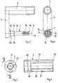
- the roll holder according to the invention contains, for example, a bearing body 1, on which, with little play and coaxially, a support element 2 designed as a sleeve is rotatably mounted.
- the bearing body 1 is rigidly attached to a support arm 4 running perpendicular to its axis 3, which in turn is rigidly attached to one end of a tubular element 5 and perpendicular to its axis 6, so that the bearing body 1 and the tubular element 5 are arranged parallel to one another.
- the tubular element 5 preferably has the same outer cross-section as the tubular, rod and / or node elements of a known kit for the manufacture of handles, handrails or the like (DE-OS 26 32 696), so that it is flush with the surface e.g. can each be connected to a pipe element 7 or 8 of this kit and is then separated from them only by hairline butt joints.
- the joints protrude through, for example, a tubular metal insert 9 inserted into the tubular elements 5, 7 and 8 and having a corresponding outer diameter.
- the tubular element 5 can be held non-rotatably on the likewise non-rotatably mounted metal insert 9, for example, by providing the surface of the metal insert 9 with knurling.
- the bearing body 1 at its end remote from the support arm 4 has a cylindrical section 10, which at its end facing the support arm 4 first stepwise into a cross-sectionally widened but coaxially arranged section 11 and then via a further step into a section 12 bordering on the support arm 4 and also coaxial to the axis 3, which section is again widened in cross section compared to section 11.
- a coaxial threaded bore 15 is formed in the end face 14 located at the free end of the bearing body 1.
- an extension 15 projecting beyond the end face 14 is provided at this end, the cross section of which is designed in the manner of a segment of a circle, as shown in particular in FIG. 4.
- the support element 2 consists of a sleeve, the outer diameter of which preferably corresponds to the outer diameter of the tubular elements 5, 7 and 8.
- the inside diameter of the support element 2 corresponds in a section 17 essentially to the outside diameter of the section 10 of the bearing body 1, while an adjoining section 18 of the support element has an inside diameter that corresponds essentially to the outer diameter of section 12 of bearing body 1.
- the support element 2 has at least one, preferably four grooves 21 which run parallel to its axis 20 and are T-shaped in cross section. These extend over the entire section 17 and border with their narrowed areas on the outer lateral surface of the support element 2.
- the support element 2 is finally provided with at least one radially protruding holding member 22 which, when the support element 2 is at least partially inserted into the cylindrical core or the like.
- a household or toilet paper roll or the like, against the inner edge thereof sets that the roller is held with a snug fit and rotatably on the support member 2.
- holding members 22 preferably several, in particular four, holding members 22 of this type are provided, which are distributed at uniform angular intervals on the circumference of the support element 2. 7 to 9, these holding members 22 consist of resiliently mounted spreading strips with an essentially rectangular cross section.
- each cross piece 23 On a narrow side, these have a transverse web 23 which extends over their entire length, so that an overall T-shaped profile with an outer cross section corresponding essentially to the inner cross section of the grooves 21 results.
- a rectangular recess 24 is also formed in each cross piece 23. 1 and 2 are inserted into the T-shaped grooves of the support element 2 or inserted in the axial direction in such a way that their transverse webs 23 come to lie in the wider areas of the grooves 21 and the sections with a rectangular cross section project radially outwards through the narrowed areas of the grooves 21.
- a spring element 25 preferably a leaf spring, is supported (FIG. 2), so that the holding members 22 are resiliently and radially biased outwards.
- the holding members 22 expediently each have a run-on slope 26 (FIGS.
- the support element 2 is pushed onto the bearing body 1 in such a way that the section 17 comes to rest on the section 10 and the section 18 partly on the section 12.
- the cross sections are dimensioned so that there is a largely wobble-free sliding fit and the support element 2 is rotatably arranged on the bearing body 1.
- a device for braking the roll when pulling off the material web is also provided. Since the roller itself is held in a rotationally fixed manner on the support element 2, the braking device has cooperating means on the bearing body 1 and on the support element 2. Preferably, however, the support element 2 is in use under the influence of an adjustable braking force.
- a fastening part 27 shown in FIGS. 10 to 13 is used for this purpose, which essentially consists of a sleeve with a cylindrical outer jacket corresponding in cross section to the outer cross section of the support element 2, the one sleeve end being closed by a base 28 with a central through opening 29, so that there is an overall cup or cap shape.
- the bottom 28 has a rear extension 30 which is penetrated by the through bore 29 and which is essentially cylindrical and has an outer diameter corresponding to the diameter of the section 10 of the bearing body 2.
- This extension 30 is also provided along a line 31 (FIG. 12) with a cutout which corresponds exactly to the extension 16 in its shape.
- the fastening part 27 On its front inner jacket, the fastening part 27 has a circumferential undercut 33 for producing a snap connection with a cover disk 32 only shown in FIG. 1.
- the support element 2 with the holding members 22 already inserted is placed on the bearing body 1 in such a way that the front end of the section 18 comes to rest on the section 12 and a friction surface 34 formed by the different cross sections of the sections 17 and 18 (FIG. 6) against a friction surface 35 (FIG. 3), which is formed by the different cross sections of the sections 10 and 11 of the bearing body 1.
- the section 18 is dimensioned so large in the axial direction that a small gap 36 (FIG. 1) remains between its free end and the support arm 4.
- a small gap 36 (FIG. 1) remains between its free end and the support arm 4.
- its shoulder 16 is then arranged in the last end piece of the section 17 of the support element 2.
- the extension 30 is now inserted into the space remaining between the extension 16 and the support element 2 such that the extensions 16 and 30 along the line 31 (FIG. 12) form a cylinder with a diameter of the section 10 of the bearing body 1 Add the corresponding diameter, as shown in FIG. 1, and thereby simultaneously form a rotation lock, which prevents the fastening part 27 from rotating relative to the bearing body 1 about the axis 3.
- the free end face of the support element 2 forms a further friction surface 37 (FIG. 6), against which a friction surface 38 of the fastening part 27 surrounding the attachment 30 applies, wherein neither the free end of the extension 16 with the friction surface 38 nor the free end of the extension 30 comes into contact with the free end surface 14 (FIG. 3) of the bearing body 1.
- the fastening part 27 also forms an extension of the support element 2 that is flush with the surface.
- An adjusting screw 40 (FIG. 1) is then screwed through the through opening 29 of the fastening part 27 into the threaded bore 15.
- the support element 2 is axially fixed on the bearing body 1.
- the head 41 of the adjusting screw 40 lies against the edge of the through bore 29, so that when the adjusting screw 40 is tightened further, the friction surfaces 34, 35 and 37, 38 are pressed against one another.
- a defined braking force which is dependent on the setting of the adjusting screw 40 is exerted on the support element 2.
- the fastening part 27 cannot rotate when the support element 2 is rotated, so that the braking force once selected is retained regardless of whether and how often the support element 2 is rotated.
- strong compression spring 42 is provided, which is supported between the friction surface 34 and a further friction surface 43, which is formed by the change in diameter between the sections 11 and 12 of the bearing body 1 (FIG. 3), such that only the friction surfaces 37, 38 in Are in contact while the support member 2 is at the other end under the influence of the compression spring 42.
- the roll holder After the cover disk 32 has been pressed onto the fastening part 27, the roll holder is ready for operation. It is now from the side of the cover plate 32 ago a role, not shown, on the fastening part 27 and the Tragele ment 2 pushed, the holding members 22 depending on the diameter of the receiving opening of the roller more or less strongly, but resiliently, are pressed into the grooves 21 of the support element 2, so that they always with a firm press fit against fluctuations or different diameters of the receiving opening the walls of which are pressed and hold the roller in a rotationally fixed manner on the supporting element 2. If the material web wound up from this is therefore pulled off, then the roller rotates only in accordance with the preselected braking force exerted on the supporting element 2. If a section of the material web is to be torn off along a perforation or the like, only a jerky pull need be exerted on this section without it being necessary to hold the roll or the support element 2 by hand.
- the controllability of the braking force allows adaptation to different types of paper and can always be preselected by adjusting the adjusting screw 40 so that the respective material web can be slowly removed without tearing, and that a preselected section can be separated by exerting a certain tear-off force. Therefore, especially disabled people with nervous dysfunction or poor comprehension can always take hold of the exposed end of the material web and tear off a new section of material if necessary.
- the fastening part 27 is provided on the side with a recess 44 (FIGS. 1, 10, 11, 13) into which a tool can be inserted in order to Lever off cover plate 32 from fastening part 27.
- cover plate 32 When using the roll holder in public buildings such as hospitals, schools or the like, it is often undesirable to attach the cover plate 32 easily detachable. It would therefore be possible to omit the recess 44 of the fastening part 27 and instead to provide the cover plate 32 with a small central bore through which authorized persons can insert a small screwdriver or Allen key and thus actuate the adjusting screw 40 even if the cover plate 32 is not removed. It would also be conceivable for the cover disk 32 to be designed in such a way that, when it rotates, the adjusting screw 40 is rotated at the same time, but the cover disk 32 is not thereby also released from the fastening part 27. However, it is particularly advantageous to provide a cover plate 46, which is shown in FIGS. 14 to 17. The embodiment shown in FIG. 14 is identical to the embodiment according to FIG. 1 except for the different cover plate 46.
- the cover plate 46 has on its back a sleeve-like extension 47 which fits exactly into the cylindrical fastening part 27. This is provided on its bottom 28 with a rectangular recess 48 (FIGS. 10, 11) in which one leg of an angle piece 49 made of a resilient material (FIG. 14) is arranged. The attachment takes place by means of the adjusting screw 40 which projects through an opening of this leg. A leg of the angle piece 49 which is bent through 90 ° projects parallel to the axis 3 into the projection 47 and is provided at its free end with a latching hook 50.
- the extension 47 has on its inside a parallel groove 51 running parallel to its axis, in the bottom of which there is an opening 52 corresponding in size to the cross section of the latching hook 50, which has a semicircular part close to the cover plate 46 Section 53 with a very small radius (eg maximum 1 mm) is extended.
- the arrangement is like this made that the locking hook 50 snaps into the opening 52 when inserting the projection 47 into the opening 52, whereby the cover plate 46 is axially locked with the fastening part 27 and no fastening means are visible from the outside. In this case, however, the recess 44 (FIG.
- the cover disk 46 preferably has a diameter which is larger than the diameter of the receiving opening or the core of the rolls to be placed on the roll holder. This also provides a useful anti-theft device against unauthorized removal of the entire roller, which cannot be removed after the cover disk 46 has been locked with the fastening part 27.
- the hole provided for pushing away the locking hook 50 can also be placed in a position which is covered by the roller or its core after the roller has been pushed onto the fastening part 27 and the supporting element 2 is.
- the sum of the axial lengths of the support element 2 and the fastening part 27 can be dimensioned in such a way that the usual axial length of the rollers corresponds.
- the cover plate 46 can only be removed from the fastening part 27 even by authorized persons after the roll has been completely unwound and, if necessary, after its core has been destroyed.
- guides are preferably provided which only allow the sliding on in a relative rotational angle position. These tours are e.g. from a projecting web 54 (FIGS. 10 and 11) on the inside of the fastening part 27 and a slot 55 receiving this (FIGS. 15 and 16) on the outer circumference of the shoulder 47 of the cover plate 46. As can be seen in particular in FIGS. 10 to 13 regardless of which cover plate 32, 46 it is to be combined with, the fastening part 27 is always of the same design.
- the invention is not limited to the exemplary embodiments described, which can be modified in many ways. It is possible, for example, to omit the fastening part 27 and to let the head 41 of the adjusting screw 40 rest on the outer end face of the support element 2.
- the friction surfaces in engagement between the supporting element 2 and the head 41 can be chosen to be so small that the adjusting screw 40 cannot rotate when the supporting element 2 is turned.
- a comparatively long adjusting screw 40 can be used and at least the section 10 of the supporting body 1 can be made of plastic, so that there is a self-locking effect in the threaded sections and large friction surfaces preventing the adjusting screw 40 from turning.
- the bearing body 1 can also be attached to any other mounting bodies and can be mounted together with these directly on a wall or the like, whereby a vertical arrangement of the bearing body 1 to the wall or the like is also possible.
- the bearing body 1, the support arm 4 and the tubular element 5 are preferably made of plastic and in one piece by injection molding.
- the support element 2, the holding members 22, the fastening part 27 and the cover plates 32 and 46 preferably also consist of plastic bodies produced by injection molding.
- FIGS. 18 and 19 A further embodiment of the roll holder according to the invention can be seen from FIGS. 18 and 19, the same reference numerals being used for the same parts.
- the bearing body 1 is not on the support arm 4 and with this on the tubular element 5, but on a e.g. made of steel or plastic attached lower part 61, which is provided with a plurality of holes 62 indicated in FIG. 19 for receiving fastening screws.
- the lower part 61 consists of a flat, substantially plane-parallel disk which is attached to a wall or the like and is connected to the bearing body 1 in such a way that it is essentially vertical after the attachment of the lower part 61 to the wall or the like protrudes from this.
- a cover cap 63 is used to cover the lower part 61, which has approximately the same external cross section as the lower part 61 and can be connected to the latter by undercuts or the like formed on the circumference.
- the cover cap 63 has a central receiving opening 64 (FIG. 19), the cross section of which essentially corresponds to the cross section of the section 18 of the support element 2 and receives the end remote from the fastening part 27. 18 and 19, the lower part 61 is expediently first attached to the wall or the like, then the cover cap 63 is pulled over the bearing body 1 and then the support element 2 is placed on the bearing body 1 and into the receiving opening 64 introduced.
Landscapes
- Unwinding Webs (AREA)
- Replacement Of Web Rolls (AREA)
- Rolls And Other Rotary Bodies (AREA)
- Preliminary Treatment Of Fibers (AREA)
- Treatment Of Fiber Materials (AREA)
- Liquid Crystal (AREA)
Priority Applications (1)
| Application Number | Priority Date | Filing Date | Title |
|---|---|---|---|
| AT88113584T ATE97635T1 (de) | 1987-09-04 | 1988-08-20 | Rollenhalter. |
Applications Claiming Priority (2)
| Application Number | Priority Date | Filing Date | Title |
|---|---|---|---|
| DE3729559 | 1987-09-04 | ||
| DE19873729559 DE3729559A1 (de) | 1987-09-04 | 1987-09-04 | Rollenhalter |
Publications (3)
| Publication Number | Publication Date |
|---|---|
| EP0305836A2 true EP0305836A2 (fr) | 1989-03-08 |
| EP0305836A3 EP0305836A3 (en) | 1990-04-18 |
| EP0305836B1 EP0305836B1 (fr) | 1993-11-24 |
Family
ID=6335194
Family Applications (1)
| Application Number | Title | Priority Date | Filing Date |
|---|---|---|---|
| EP88113584A Expired - Lifetime EP0305836B1 (fr) | 1987-09-04 | 1988-08-20 | Support de rouleau |
Country Status (4)
| Country | Link |
|---|---|
| US (1) | US4878631A (fr) |
| EP (1) | EP0305836B1 (fr) |
| AT (1) | ATE97635T1 (fr) |
| DE (2) | DE3729559A1 (fr) |
Families Citing this family (15)
| Publication number | Priority date | Publication date | Assignee | Title |
|---|---|---|---|---|
| US5833169A (en) * | 1993-09-02 | 1998-11-10 | G. H. Wood & Wyant Inc. | Large roll bathroom tissue dispenser with stub roll holder |
| US5370339A (en) * | 1993-12-01 | 1994-12-06 | James River Paper Company, Inc. | Apparatus for dispensing web material from a coreless roll and for resisting end-wise removal of the roll until substantial depletion thereof |
| US5564645A (en) * | 1995-02-24 | 1996-10-15 | Minnesota Mining And Manufacturing Company | Roll support hub braking mechanism |
| FR2750969B1 (fr) * | 1996-07-12 | 1998-11-20 | Jamont N V | Distributeur pour bande de materiau en rouleau sans mandrin comportant une tige support perfectionnee |
| DE19733051A1 (de) * | 1997-07-31 | 1999-02-04 | Ingo Dipl Ing Walter | Vorrichtung zum abrollbaren Halten einer Papierrolle |
| DE19841190C2 (de) * | 1998-09-09 | 2002-10-10 | Ille Papier Service Gmbh | Brems- und Haltevorrichtung für eine Papierrolle, insbesondere Papierrolle für einen Handtuchspender |
| US6199786B1 (en) * | 1999-02-19 | 2001-03-13 | Ipl, Inc. | Wire reel assembly and wire reel therefor |
| USD448592S1 (en) | 2000-10-27 | 2001-10-02 | Mcbride John | Paper towel holder |
| GB2385581B (en) * | 2002-02-22 | 2004-01-21 | David Molloy | Paper roll - stabilising bar |
| USD550488S1 (en) | 2006-03-08 | 2007-09-11 | Umbra Llc | Rolled product dispenser |
| US7438256B2 (en) | 2006-03-08 | 2008-10-21 | Umbra Llc | Rolled product dispenser |
| DE102007001672B4 (de) * | 2007-01-11 | 2011-03-10 | Koenig & Bauer Aktiengesellschaft | Wechselkonus |
| EP2448852B1 (fr) * | 2009-06-30 | 2017-11-22 | Sca Hygiene Products AB | Axe et support d'axe |
| WO2014007689A1 (fr) * | 2012-07-02 | 2014-01-09 | Sca Hygiene Products Ab | Distributeur |
| US10512369B2 (en) * | 2016-11-09 | 2019-12-24 | Jojo De Vera Cuenca | Toilet paper roll holder attachment system |
Family Cites Families (19)
| Publication number | Priority date | Publication date | Assignee | Title |
|---|---|---|---|---|
| US1674285A (en) * | 1928-06-19 | Holder for | ||
| US1354170A (en) * | 1919-10-29 | 1920-09-28 | Chicago Hardware Foundry Compa | Toilet-paper fixture |
| DE463665C (de) * | 1927-05-29 | 1928-08-02 | Alois Siebeck Dipl Ing | Halter fuer Klosettpapierrollen |
| US2073429A (en) * | 1936-04-15 | 1937-03-09 | Spicher Jay Lloyd | Toilet paper roll holder |
| US2419798A (en) * | 1945-05-01 | 1947-04-29 | Guthrie B Stone | Toilet tissue holder |
| US2576254A (en) * | 1947-05-28 | 1951-11-27 | Celanese Corp | Yarn package support |
| US2613041A (en) * | 1951-04-03 | 1952-10-07 | Lonnie O Cantrell | Paper roll holder |
| US2889121A (en) * | 1952-02-16 | 1959-06-02 | Lawrence A Heinle | Toilet paper roll core |
| DE1289275B (de) * | 1961-11-20 | 1969-02-13 | Jend Paul | Halter fuer Papierbahnen in Rollenform, insbesondere Toilettenpapier |
| US3292874A (en) * | 1964-07-30 | 1966-12-20 | Herbert M Tinkham | Roll holder |
| US3281089A (en) * | 1965-03-22 | 1966-10-25 | Alwin Mfg Company | Core brake for a web dispenser |
| US3360208A (en) * | 1965-07-26 | 1967-12-26 | Juan L Winkler | Apparatus for winding textile threads |
| GB1294568A (en) * | 1970-08-01 | 1972-11-01 | Walmor Engineering Co Ltd | Improvements in the mounting of reels on winding machines |
| US3738588A (en) * | 1971-08-13 | 1973-06-12 | Mallory & Co Inc P R | Calibrated tension arbor |
| US3788573A (en) * | 1972-02-07 | 1974-01-29 | Raymond Lee Organization Inc | Roll paper dispenser |
| US4102513A (en) * | 1977-09-14 | 1978-07-25 | Twyman Guard | Film wrapping dispenser |
| US4783016A (en) * | 1980-09-08 | 1988-11-08 | Minnesota Mining And Manufacturing Company | Roll holder with retention member |
| US4660781A (en) * | 1984-12-20 | 1987-04-28 | Scott Paper Company | Roll tissue dispenser |
| EP0300695A3 (fr) * | 1987-07-18 | 1990-07-25 | Jeffrey Simpson Vassie | Système de manipulation d'une matière en feuille et distributeur et appareil d'enroulement pour son usage |
-
1987
- 1987-09-04 DE DE19873729559 patent/DE3729559A1/de not_active Withdrawn
-
1988
- 1988-08-20 DE DE88113584T patent/DE3885820D1/de not_active Expired - Fee Related
- 1988-08-20 AT AT88113584T patent/ATE97635T1/de not_active IP Right Cessation
- 1988-08-20 EP EP88113584A patent/EP0305836B1/fr not_active Expired - Lifetime
- 1988-09-02 US US07/240,840 patent/US4878631A/en not_active Expired - Fee Related
Also Published As
| Publication number | Publication date |
|---|---|
| DE3885820D1 (de) | 1994-01-05 |
| ATE97635T1 (de) | 1993-12-15 |
| EP0305836B1 (fr) | 1993-11-24 |
| DE3729559A1 (de) | 1989-03-16 |
| US4878631A (en) | 1989-11-07 |
| EP0305836A3 (en) | 1990-04-18 |
Similar Documents
| Publication | Publication Date | Title |
|---|---|---|
| EP0305836B1 (fr) | Support de rouleau | |
| DE2625182B2 (de) | Beschlag zum lösbaren Verbinden von zwei Bauteilen, insbesondere plattenförmigen Bauteilen für Möbel | |
| EP0413012A1 (fr) | Dispositif de liaison liberable pour elements de jeux de construction. | |
| DE2610200C3 (de) | Beschlag zum lösbaren Verbinden zweier Bauteile, insbesondere von plattenförmigen Bauteilen für Möbel | |
| DD299202A5 (de) | Vorrichtung zur befestigung eines insbesondere rohrfoermigen bauteils an einer wand oder dgl. | |
| WO2000014371A1 (fr) | Charniere a visser comportant une position d'arret | |
| DE2906516C1 (de) | Brillenscharnier | |
| DE202007008827U1 (de) | Vorrichtung mit einem Unterteil und einer Rückholfeder zur drehbaren Lagerung eines Ausstattungsteils, insbesondere eines Türdrückers | |
| EP0804106B1 (fr) | Dispositif servant a recevoir et a distribuer une matiere applicable | |
| EP2284342A2 (fr) | Charnière avec surface d'appui encochée | |
| DE9319981U1 (de) | Vorrichtung zur axial unverschieblichen, aber leicht lösbaren Verbindung eines Ausstattungsteils mit einem Montageteil | |
| DE8703609U1 (de) | Betätigungsgriff für ein Sanitärventil | |
| DE2201546A1 (de) | Tuerzarge mit in die zarge eingebauten tuerbaendern | |
| DE2248724A1 (de) | Tuerband | |
| DE7238210U (de) | In ein Bohrloch einzusetzender Spreizdübel | |
| DE19628982C2 (de) | Zahlenkombinationsschloß | |
| DE3833757A1 (de) | Schloss fuer eine tuer od. dgl. | |
| DE2045865C3 (de) | TürverschluB | |
| EP0430185A2 (fr) | Dispositif de fixation de carré de poignée pour l'actionnement d'une porte ou similaire | |
| DE3243858A1 (de) | Verriegelungskloben-anordnung | |
| EP1793067A2 (fr) | Ferrure pour portes, fenêtres ou similaires | |
| EP0219511A1 (fr) | Dispositif de fixation de vis | |
| EP0920828B1 (fr) | Objet d'usage en forme d'une pièce d'équipement en particulier un porte-serviette | |
| DE2019955A1 (de) | In eine Montagewand loesbar einsetzbare Befestigungsvorrichtung | |
| DE2647776A1 (de) | Moebelscharnier |
Legal Events
| Date | Code | Title | Description |
|---|---|---|---|
| PUAI | Public reference made under article 153(3) epc to a published international application that has entered the european phase |
Free format text: ORIGINAL CODE: 0009012 |
|
| AK | Designated contracting states |
Kind code of ref document: A2 Designated state(s): AT BE CH DE FR GB IT LI NL |
|
| PUAL | Search report despatched |
Free format text: ORIGINAL CODE: 0009013 |
|
| AK | Designated contracting states |
Kind code of ref document: A3 Designated state(s): AT BE CH DE FR GB IT LI NL |
|
| 17P | Request for examination filed |
Effective date: 19900924 |
|
| 17Q | First examination report despatched |
Effective date: 19920522 |
|
| GRAA | (expected) grant |
Free format text: ORIGINAL CODE: 0009210 |
|
| AK | Designated contracting states |
Kind code of ref document: B1 Designated state(s): AT BE CH DE FR GB IT LI NL |
|
| REF | Corresponds to: |
Ref document number: 97635 Country of ref document: AT Date of ref document: 19931215 Kind code of ref document: T |
|
| GBT | Gb: translation of ep patent filed (gb section 77(6)(a)/1977) |
Effective date: 19931125 |
|
| REF | Corresponds to: |
Ref document number: 3885820 Country of ref document: DE Date of ref document: 19940105 |
|
| ET | Fr: translation filed | ||
| ITF | It: translation for a ep patent filed | ||
| PLBE | No opposition filed within time limit |
Free format text: ORIGINAL CODE: 0009261 |
|
| STAA | Information on the status of an ep patent application or granted ep patent |
Free format text: STATUS: NO OPPOSITION FILED WITHIN TIME LIMIT |
|
| 26N | No opposition filed | ||
| PGFP | Annual fee paid to national office [announced via postgrant information from national office to epo] |
Ref country code: FR Payment date: 20000731 Year of fee payment: 13 |
|
| PGFP | Annual fee paid to national office [announced via postgrant information from national office to epo] |
Ref country code: BE Payment date: 20000801 Year of fee payment: 13 |
|
| PGFP | Annual fee paid to national office [announced via postgrant information from national office to epo] |
Ref country code: CH Payment date: 20000808 Year of fee payment: 13 |
|
| PGFP | Annual fee paid to national office [announced via postgrant information from national office to epo] |
Ref country code: GB Payment date: 20000816 Year of fee payment: 13 |
|
| PGFP | Annual fee paid to national office [announced via postgrant information from national office to epo] |
Ref country code: AT Payment date: 20000824 Year of fee payment: 13 |
|
| PGFP | Annual fee paid to national office [announced via postgrant information from national office to epo] |
Ref country code: NL Payment date: 20000829 Year of fee payment: 13 |
|
| PGFP | Annual fee paid to national office [announced via postgrant information from national office to epo] |
Ref country code: DE Payment date: 20001026 Year of fee payment: 13 |
|
| PG25 | Lapsed in a contracting state [announced via postgrant information from national office to epo] |
Ref country code: GB Free format text: LAPSE BECAUSE OF NON-PAYMENT OF DUE FEES Effective date: 20010820 Ref country code: AT Free format text: LAPSE BECAUSE OF NON-PAYMENT OF DUE FEES Effective date: 20010820 |
|
| PG25 | Lapsed in a contracting state [announced via postgrant information from national office to epo] |
Ref country code: LI Free format text: LAPSE BECAUSE OF NON-PAYMENT OF DUE FEES Effective date: 20010831 Ref country code: CH Free format text: LAPSE BECAUSE OF NON-PAYMENT OF DUE FEES Effective date: 20010831 Ref country code: BE Free format text: LAPSE BECAUSE OF NON-PAYMENT OF DUE FEES Effective date: 20010831 |
|
| BERE | Be: lapsed |
Owner name: HEINRICH WILKE G.M.B.H. HEWI Effective date: 20010831 |
|
| PG25 | Lapsed in a contracting state [announced via postgrant information from national office to epo] |
Ref country code: NL Free format text: LAPSE BECAUSE OF NON-PAYMENT OF DUE FEES Effective date: 20020301 |
|
| GBPC | Gb: european patent ceased through non-payment of renewal fee |
Effective date: 20010820 |
|
| REG | Reference to a national code |
Ref country code: CH Ref legal event code: PL |
|
| PG25 | Lapsed in a contracting state [announced via postgrant information from national office to epo] |
Ref country code: FR Free format text: LAPSE BECAUSE OF NON-PAYMENT OF DUE FEES Effective date: 20020430 |
|
| NLV4 | Nl: lapsed or anulled due to non-payment of the annual fee |
Effective date: 20020301 |
|
| PG25 | Lapsed in a contracting state [announced via postgrant information from national office to epo] |
Ref country code: DE Free format text: LAPSE BECAUSE OF NON-PAYMENT OF DUE FEES Effective date: 20020501 |
|
| REG | Reference to a national code |
Ref country code: FR Ref legal event code: ST |
|
| PG25 | Lapsed in a contracting state [announced via postgrant information from national office to epo] |
Ref country code: IT Free format text: LAPSE BECAUSE OF NON-PAYMENT OF DUE FEES;WARNING: LAPSES OF ITALIAN PATENTS WITH EFFECTIVE DATE BEFORE 2007 MAY HAVE OCCURRED AT ANY TIME BEFORE 2007. THE CORRECT EFFECTIVE DATE MAY BE DIFFERENT FROM THE ONE RECORDED. Effective date: 20050820 |