EP0305905A2 - Système d'informations routières - Google Patents
Système d'informations routières Download PDFInfo
- Publication number
- EP0305905A2 EP0305905A2 EP19880113903 EP88113903A EP0305905A2 EP 0305905 A2 EP0305905 A2 EP 0305905A2 EP 19880113903 EP19880113903 EP 19880113903 EP 88113903 A EP88113903 A EP 88113903A EP 0305905 A2 EP0305905 A2 EP 0305905A2
- Authority
- EP
- European Patent Office
- Prior art keywords
- transmitter
- reflection body
- traffic information
- information system
- road boundary
- Prior art date
- Legal status (The legal status is an assumption and is not a legal conclusion. Google has not performed a legal analysis and makes no representation as to the accuracy of the status listed.)
- Granted
Links
Images

Classifications
-
- E—FIXED CONSTRUCTIONS
- E01—CONSTRUCTION OF ROADS, RAILWAYS, OR BRIDGES
- E01F—ADDITIONAL WORK, SUCH AS EQUIPPING ROADS OR THE CONSTRUCTION OF PLATFORMS, HELICOPTER LANDING STAGES, SIGNS, SNOW FENCES, OR THE LIKE
- E01F9/00—Arrangement of road signs or traffic signals; Arrangements for enforcing caution
- E01F9/60—Upright bodies, e.g. marker posts or bollards; Supports for road signs
- E01F9/604—Upright bodies, e.g. marker posts or bollards; Supports for road signs specially adapted for particular signalling purposes, e.g. for indicating curves, road works or pedestrian crossings
- E01F9/615—Upright bodies, e.g. marker posts or bollards; Supports for road signs specially adapted for particular signalling purposes, e.g. for indicating curves, road works or pedestrian crossings illuminated
- E01F9/617—Illuminated or wired-up posts, bollards, pillars or like upstanding bodies or structures for traffic guidance, warning or control
-
- E—FIXED CONSTRUCTIONS
- E01—CONSTRUCTION OF ROADS, RAILWAYS, OR BRIDGES
- E01F—ADDITIONAL WORK, SUCH AS EQUIPPING ROADS OR THE CONSTRUCTION OF PLATFORMS, HELICOPTER LANDING STAGES, SIGNS, SNOW FENCES, OR THE LIKE
- E01F9/00—Arrangement of road signs or traffic signals; Arrangements for enforcing caution
- E01F9/60—Upright bodies, e.g. marker posts or bollards; Supports for road signs
- E01F9/604—Upright bodies, e.g. marker posts or bollards; Supports for road signs specially adapted for particular signalling purposes, e.g. for indicating curves, road works or pedestrian crossings
- E01F9/619—Upright bodies, e.g. marker posts or bollards; Supports for road signs specially adapted for particular signalling purposes, e.g. for indicating curves, road works or pedestrian crossings with reflectors; with means for keeping reflectors clean
Definitions
- the invention relates to a traffic information system according to the preamble of patent claim 1.
- a conventional emergency call station also serves as a transmitter for optical information signals.
- Such emergency call pillars are usually only arranged on motorways and are at least 1 km apart.
- the invention solves this problem in that the transmitter is arranged in a commercially available road boundary post containing a reflection body.
- such a road boundary post does not differ from one in which such a transmitter is missing. If one considers a section of the route, such a transmitter can be arranged in each road boundary post and thus, due to the generally short distance of 50 m, a dense network of such transmitters and thus an effective road-parallel traffic information system can be installed. The density can also be varied by only accommodating such a transmitter in every second road boundary post.
- the transmitter does not appear optically or only insignificantly, if it is deactivated, it is difficult for the driver to distinguish sections of the route with and without such a traffic information system. He will never rely on such a system to automatically and promptly alert you to an impending danger. As a consequence, this means that the driver does not change his driving behavior to the disadvantage compared to the situation in which such a traffic information system is not installed.
- the transmitter can be arranged within the field in which the reflection body is located. This makes it even more difficult to distinguish whether a road boundary post is equipped with such a transmitter if it is deactivated. Regardless of this, the transmitter is visually striking if it is activated. The goal of not letting the vehicle user easily recognize whether he is traveling on a route section with or without such a traffic information system is thus achieved even better.
- Another improvement is to conceal the surface of the transmitter by having a surface texture that corresponds to that of the reflection body. A deactivated transmitter therefore no longer appears optically.
- the arrangement of the transmitter seen in the viewing direction, results behind the reflection body, which is transparent to the radiation emitted by the transmitter, a particularly advantageous embodiment of the invention.
- the advantage of this is that the reflection body remains effective at night and the presence of a deactivated transmitter is therefore not recognizable to the vehicle user even at night.
- the reflection body has an unrestrictedly effective surface.
- the effect of the reflection body is canceled by the activated transmitter, which then outshines the reflection body and, in particular when it is not directly exposed to direct illumination of motor vehicle lights, develops its effect.
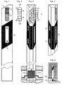
- a transmitter 2 for optical information signals is contained in a commercially available road boundary post 1.
- the transmitter 2 is located in the head segment of the road boundary post 1 and is formed in two parts from an indicator light 3 for red and an indicator light 4 for a yellow light signal.
- a reflection body 6 in a black-painted field 5 defined by oblique boundary lines, which reflects incident headlight light and thus marks the roadside in connection with the following corresponding road boundary posts, not shown, posted on the roadside.
- the surface of the transmitter 2 can be designed in color so that it does not differ, or only insignificantly, from the surroundings in the (usually white) head segment of the road boundary post when the transmitter is deactivated. It is therefore not readily apparent to the vehicle user that the road boundary post is equipped with such a transmitter if the transmitter is deactivated. The driver is therefore not prompted by such a road delimitation post to change his driving behavior and, for example, to be led to the possibly incorrect assumption that the following section of the route is safe to drive on.
- the transmitter 2 in a road boundary post that has not been changed or has changed only insignificantly compared to a conventional post when the transmitter is not activated, it is possible to equip sections of the route with such transmitters in a more or less dense sequence.
- the optimal arrangement density also depends on the course of the road, with a sequence of transmitters at the usual distance of 50 to 100 meters if necessary provides effective warning or information for the vehicle user.
- the transmitter no longer appears in the deactivated state.
- the transmitter 2 is now arranged directly behind the reflection body 6, which is opaque to the optical signals of the transmitter.
- the transmitter can be located behind the reflection body 6 on the front side facing the vehicle user or else on the rear side, in which a two-part reflection body 7 is present. In the exemplary embodiment, only the arrangement behind the reflection body 6 is shown.
- the transmitter consists of two lights 8, each consisting of a lamp 9, a reflector 10 and a transparent, red or yellow film 11 or 11 '.
- electrical lines 12 are provided, which lead to a control part 13 in the foot 14 of the route limitation post 1.
- Control part and foot part 13 and 14 are arranged below the road surface 15 (Fig. 6).
- the control part 13 is controlled and supplied with energy by supply lines 16 which connect the road boundary posts, which are equipped with such a transmitter 2, parallel to the roadside.
- the transmitter 2 no longer appears at all, provided that it is deactivated. It is therefore not at all recognizable for the vehicle user whether the road boundary post is equipped with such a transmitter, provided the transmitter is inactive.
- the transmitter 2 Only when it is necessary to give the driver a warning or information signal is the transmitter 2 activated and emits red or yellow light through the reflection body 6. Due to the dense sequence of such transmitters, a particularly effective warning and information means can also be created, since the vehicle user can now be confronted with such warning or information signals in close succession. The prerequisite for this is that such transmitters are correspondingly frequently arranged in road boundary posts. This is theoretically possible for every post and leads to a sequence of transmitters that is the same as the sequence of the posts. Despite this high density of transmitters, due to the "invisible" housing of the transmitters, the vehicle user is not prompted to change his driving behavior in a dangerous manner due to the inactivity of the transmitters.
Landscapes
- Engineering & Computer Science (AREA)
- Architecture (AREA)
- Civil Engineering (AREA)
- Structural Engineering (AREA)
- Traffic Control Systems (AREA)
- Navigation (AREA)
Applications Claiming Priority (2)
| Application Number | Priority Date | Filing Date | Title |
|---|---|---|---|
| DE3728949A DE3728949C2 (de) | 1987-08-29 | 1987-08-29 | Verkehrsinformationssystem |
| DE3728949 | 1987-08-29 |
Publications (3)
| Publication Number | Publication Date |
|---|---|
| EP0305905A2 true EP0305905A2 (fr) | 1989-03-08 |
| EP0305905A3 EP0305905A3 (en) | 1990-06-06 |
| EP0305905B1 EP0305905B1 (fr) | 1995-10-18 |
Family
ID=6334814
Family Applications (1)
| Application Number | Title | Priority Date | Filing Date |
|---|---|---|---|
| EP88113903A Expired - Lifetime EP0305905B1 (fr) | 1987-08-29 | 1988-08-26 | Système d'informations routières |
Country Status (3)
| Country | Link |
|---|---|
| EP (1) | EP0305905B1 (fr) |
| DE (2) | DE3728949C2 (fr) |
| ES (1) | ES2078894T3 (fr) |
Cited By (3)
| Publication number | Priority date | Publication date | Assignee | Title |
|---|---|---|---|---|
| DE9405975U1 (de) * | 1994-04-09 | 1994-07-07 | Abele, Hans-Peter, 75365 Calw | Eiswarn-Leitpfosten für öffentliche und nichtöffentliche Straßen |
| WO2009087513A1 (fr) * | 2008-01-04 | 2009-07-16 | Philips Intellectual Property & Standards Gmbh | Poteau réflecteur |
| EP4239128A1 (fr) * | 2022-03-01 | 2023-09-06 | Kursuncu Hakan | Tête auto-éclairante pour poteaux de guidage |
Families Citing this family (3)
| Publication number | Priority date | Publication date | Assignee | Title |
|---|---|---|---|---|
| DE19927752A1 (de) * | 1999-06-17 | 2001-01-11 | Glasow Renate | Markierungseinrichtung |
| DE10054077A1 (de) * | 2000-10-31 | 2002-05-08 | Thomas Topfstaedt | Funkfeststation |
| DE10060799C2 (de) * | 2000-12-07 | 2003-02-20 | Horst Doerner | Anordnung zur Erfassung von sich nähernden Fahrzeugen, insbesondere von in falscher Richtung fahrenden Fahrzeugen |
Family Cites Families (9)
| Publication number | Priority date | Publication date | Assignee | Title |
|---|---|---|---|---|
| DE6602329U (de) * | 1966-12-12 | 1969-05-22 | Hans Gubela | Beleuchteter leitpfosten |
| DE1566921B2 (de) * | 1967-10-10 | 1972-01-13 | Rapp, Egbert, Dipl Ing , 7500 Karlsruhe | Verfahren und einrichtung zur steuerung des verkehrs auf autostrassen |
| DE7012891U (de) * | 1970-04-09 | 1970-07-23 | Britsch Walter | Strassenleitpfosten mit sicherungsleuchten. |
| DE2718352C2 (de) * | 1977-04-25 | 1979-06-28 | Hans-Juergen 3101 Hambuehren Laube | Leitpfosten für Fahrbahnen |
| DE2940205A1 (de) * | 1979-10-04 | 1981-04-16 | Karl-Gottfried Dr. 7000 Stuttgart Reinsch | Vorrichtung zum warnen vor eisglaettegefahr |
| DE8115286U1 (de) * | 1981-05-22 | 1982-05-06 | FAE Funk-Ampel & Elektrogeräte GmbH, 5200 Siegburg | Strassen-leitpfosten |
| DE3332229A1 (de) * | 1983-09-07 | 1985-03-21 | Günter 4972 Löhne Offhaus | Warnvorrichtung zur absicherung von gefahrenstellen im strassenverkehr |
| US4893903A (en) * | 1985-05-06 | 1990-01-16 | Taliq Corporation | Flashing advisory sign |
| JP4176076B2 (ja) * | 2002-11-08 | 2008-11-05 | 華為技術有限公司 | 無線lanユーザの在席情報のやりとりを行うための方法、システムおよび端末 |
-
1987
- 1987-08-29 DE DE3728949A patent/DE3728949C2/de not_active Expired - Lifetime
-
1988
- 1988-08-26 ES ES88113903T patent/ES2078894T3/es not_active Expired - Lifetime
- 1988-08-26 EP EP88113903A patent/EP0305905B1/fr not_active Expired - Lifetime
- 1988-08-26 DE DE3854596T patent/DE3854596D1/de not_active Expired - Lifetime
Cited By (4)
| Publication number | Priority date | Publication date | Assignee | Title |
|---|---|---|---|---|
| DE9405975U1 (de) * | 1994-04-09 | 1994-07-07 | Abele, Hans-Peter, 75365 Calw | Eiswarn-Leitpfosten für öffentliche und nichtöffentliche Straßen |
| WO2009087513A1 (fr) * | 2008-01-04 | 2009-07-16 | Philips Intellectual Property & Standards Gmbh | Poteau réflecteur |
| US8593303B2 (en) | 2008-01-04 | 2013-11-26 | Koninklijke Philips N.V. | Reflector pole |
| EP4239128A1 (fr) * | 2022-03-01 | 2023-09-06 | Kursuncu Hakan | Tête auto-éclairante pour poteaux de guidage |
Also Published As
| Publication number | Publication date |
|---|---|
| ES2078894T3 (es) | 1996-01-01 |
| DE3728949A1 (de) | 1989-03-09 |
| DE3728949C2 (de) | 1995-03-23 |
| DE3854596D1 (de) | 1995-11-23 |
| EP0305905A3 (en) | 1990-06-06 |
| EP0305905B1 (fr) | 1995-10-18 |
Similar Documents
| Publication | Publication Date | Title |
|---|---|---|
| DE3642788A1 (de) | Notfahrzeug-verkehrssteuerschaltung | |
| EP3527426B1 (fr) | Dispositif d'affichage pour un véhicule automobile ainsi que véhicule automobile doté d'un dispositif d'affichage | |
| DE102018206087A1 (de) | Verfahren zur Kommunikation eines Kraftfahrzeugs mit einem Verkehrsteilnehmer sowie Kraftfahrzeug zur Durchführung des Verfahrens | |
| DE102018206040A1 (de) | Verfahren zur Kommunikation eines Kraftfahrzeugs mit einem Verkehrsteilnehmer sowie Kraftfahrzeug zur Durchführung des Verfahrens | |
| DE102019129397A1 (de) | Scheinwerfer für ein Kraftfahrzeug | |
| DE102018206042A1 (de) | Verfahren zur Kommunikation eines Kraftfahrzeugs mit einem Verkehrsteilnehmer sowie Kraftfahrzeug zur Durchführung des Verfahrens | |
| DE69817376T2 (de) | Verbesserte anzeigevorrichtung für kraftfahrzeuge | |
| EP0820900A1 (fr) | Cadre extérieur à signal multidirectionnel pour voiture de 2,4 roues ou plus | |
| DE10017297A1 (de) | Warngerät mit Mehrfachfunktion | |
| EP0305905A2 (fr) | Système d'informations routières | |
| DE2012178A1 (de) | Signalsystem fur ein Kraftfahrzeug | |
| DE19534410A1 (de) | Richtungsweisende Fahrtrichtungsanzeige für Kraftfahrzeuge und Verkehrsleiteinrichtungen im Straßenverkehr | |
| DE3201082C2 (de) | Sicherheitsanzeige für Kraftfahrzeuge | |
| DE4322605C2 (de) | Gefahrwarneinrichtung für Taxenfahrzeuge | |
| DE2117544A1 (de) | Optische Anzeigeeinrichtung für Kraftfahrzeuge | |
| DE4243693A1 (de) | Rückwärtige Signalvorrichtung für ein Straßenfahrzeug | |
| DE3639119A1 (de) | Als motorabstellhilfe dienende zusatzeinrichtung fuer eine den fahrzeug- und fussgaenger-verkehr regelnde verkehrsampel | |
| DE69934720T2 (de) | Einrichtung mit Verkehrsschilder | |
| DE2746271A1 (de) | Lichtsignalgeber an kraftfahrzeugen oder anderen schnell fahrenden landfahrzeugen | |
| DE3225407A1 (de) | Warngeraet zum anbau an kraftfahrzeuge | |
| DE69222639T2 (de) | Fahrzeug mit sirenenannäherungs-warnsignalsender | |
| DE29910191U1 (de) | Tempo-Begrenzungssystem für Land- und Wasserfahrzeuge | |
| DE19824562A1 (de) | Weichenlagemelder | |
| CH286305A (de) | Signalisierungseinrichtung an Fahrzeugen. | |
| DE4021509A1 (de) | Motorfahrzeug mit lichttechnischer einrichtung, insbesondere blinkern |
Legal Events
| Date | Code | Title | Description |
|---|---|---|---|
| PUAI | Public reference made under article 153(3) epc to a published international application that has entered the european phase |
Free format text: ORIGINAL CODE: 0009012 |
|
| AK | Designated contracting states |
Kind code of ref document: A2 Designated state(s): DE ES FR GB IT SE |
|
| PUAL | Search report despatched |
Free format text: ORIGINAL CODE: 0009013 |
|
| AK | Designated contracting states |
Kind code of ref document: A3 Designated state(s): DE ES FR GB IT SE |
|
| RHK1 | Main classification (correction) |
Ipc: G08G 1/09 |
|
| 17P | Request for examination filed |
Effective date: 19901113 |
|
| RAP3 | Party data changed (applicant data changed or rights of an application transferred) |
Owner name: BAYERISCHE MOTOREN WERKE AKTIENGESELLSCHAFT |
|
| 17Q | First examination report despatched |
Effective date: 19930510 |
|
| GRAA | (expected) grant |
Free format text: ORIGINAL CODE: 0009210 |
|
| AK | Designated contracting states |
Kind code of ref document: B1 Designated state(s): DE ES FR GB IT SE |
|
| ET | Fr: translation filed | ||
| REF | Corresponds to: |
Ref document number: 3854596 Country of ref document: DE Date of ref document: 19951123 |
|
| REG | Reference to a national code |
Ref country code: ES Ref legal event code: FG2A Ref document number: 2078894 Country of ref document: ES Kind code of ref document: T3 |
|
| GBT | Gb: translation of ep patent filed (gb section 77(6)(a)/1977) |
Effective date: 19951127 |
|
| ITF | It: translation for a ep patent filed | ||
| PLBE | No opposition filed within time limit |
Free format text: ORIGINAL CODE: 0009261 |
|
| STAA | Information on the status of an ep patent application or granted ep patent |
Free format text: STATUS: NO OPPOSITION FILED WITHIN TIME LIMIT |
|
| 26N | No opposition filed | ||
| REG | Reference to a national code |
Ref country code: GB Ref legal event code: IF02 |
|
| PGFP | Annual fee paid to national office [announced via postgrant information from national office to epo] |
Ref country code: ES Payment date: 20050805 Year of fee payment: 18 |
|
| PGFP | Annual fee paid to national office [announced via postgrant information from national office to epo] |
Ref country code: FR Payment date: 20060828 Year of fee payment: 19 |
|
| PGFP | Annual fee paid to national office [announced via postgrant information from national office to epo] |
Ref country code: IT Payment date: 20060831 Year of fee payment: 19 Ref country code: GB Payment date: 20060831 Year of fee payment: 19 |
|
| PGFP | Annual fee paid to national office [announced via postgrant information from national office to epo] |
Ref country code: DE Payment date: 20070927 Year of fee payment: 20 |
|
| PGFP | Annual fee paid to national office [announced via postgrant information from national office to epo] |
Ref country code: SE Payment date: 20060804 Year of fee payment: 19 |
|
| EUG | Se: european patent has lapsed | ||
| GBPC | Gb: european patent ceased through non-payment of renewal fee |
Effective date: 20070826 |
|
| PG25 | Lapsed in a contracting state [announced via postgrant information from national office to epo] |
Ref country code: SE Free format text: LAPSE BECAUSE OF NON-PAYMENT OF DUE FEES Effective date: 20070827 |
|
| REG | Reference to a national code |
Ref country code: FR Ref legal event code: ST Effective date: 20080430 |
|
| PG25 | Lapsed in a contracting state [announced via postgrant information from national office to epo] |
Ref country code: FR Free format text: LAPSE BECAUSE OF NON-PAYMENT OF DUE FEES Effective date: 20070831 |
|
| REG | Reference to a national code |
Ref country code: ES Ref legal event code: FD2A Effective date: 20070827 |
|
| PG25 | Lapsed in a contracting state [announced via postgrant information from national office to epo] |
Ref country code: GB Free format text: LAPSE BECAUSE OF NON-PAYMENT OF DUE FEES Effective date: 20070826 |
|
| PG25 | Lapsed in a contracting state [announced via postgrant information from national office to epo] |
Ref country code: ES Free format text: LAPSE BECAUSE OF NON-PAYMENT OF DUE FEES Effective date: 20070827 |
|
| PG25 | Lapsed in a contracting state [announced via postgrant information from national office to epo] |
Ref country code: IT Free format text: LAPSE BECAUSE OF NON-PAYMENT OF DUE FEES Effective date: 20070826 |