EP0305956A2 - Dispositif pour emballer des barres cylindriques composées d'une pluralité de pièces discoides - Google Patents
Dispositif pour emballer des barres cylindriques composées d'une pluralité de pièces discoides Download PDFInfo
- Publication number
- EP0305956A2 EP0305956A2 EP88114083A EP88114083A EP0305956A2 EP 0305956 A2 EP0305956 A2 EP 0305956A2 EP 88114083 A EP88114083 A EP 88114083A EP 88114083 A EP88114083 A EP 88114083A EP 0305956 A2 EP0305956 A2 EP 0305956A2
- Authority
- EP
- European Patent Office
- Prior art keywords
- strand
- wrapping
- wrapping station
- strands
- paper
- Prior art date
- Legal status (The legal status is an assumption and is not a legal conclusion. Google has not performed a legal analysis and makes no representation as to the accuracy of the status listed.)
- Withdrawn
Links
Images






Classifications
-
- B—PERFORMING OPERATIONS; TRANSPORTING
- B65—CONVEYING; PACKING; STORING; HANDLING THIN OR FILAMENTARY MATERIAL
- B65B—MACHINES, APPARATUS OR DEVICES FOR, OR METHODS OF, PACKAGING ARTICLES OR MATERIALS; UNPACKING
- B65B11/00—Wrapping, e.g. partially or wholly enclosing, articles or quantities of material, in strips, sheets or blanks, of flexible material
- B65B11/04—Wrapping, e.g. partially or wholly enclosing, articles or quantities of material, in strips, sheets or blanks, of flexible material the articles being rotated
-
- B—PERFORMING OPERATIONS; TRANSPORTING
- B65—CONVEYING; PACKING; STORING; HANDLING THIN OR FILAMENTARY MATERIAL
- B65B—MACHINES, APPARATUS OR DEVICES FOR, OR METHODS OF, PACKAGING ARTICLES OR MATERIALS; UNPACKING
- B65B35/00—Supplying, feeding, arranging or orientating articles to be packaged
- B65B35/30—Arranging and feeding articles in groups
- B65B35/54—Feeding articles along multiple paths to a single packaging position
-
- B—PERFORMING OPERATIONS; TRANSPORTING
- B65—CONVEYING; PACKING; STORING; HANDLING THIN OR FILAMENTARY MATERIAL
- B65B—MACHINES, APPARATUS OR DEVICES FOR, OR METHODS OF, PACKAGING ARTICLES OR MATERIALS; UNPACKING
- B65B51/00—Devices for, or methods of, sealing or securing package folds or closures; Devices for gathering or twisting wrappers, or necks of bags
- B65B51/04—Applying separate sealing or securing members, e.g. clips
- B65B51/06—Applying adhesive tape
Definitions
- the invention relates to a device for packaging cylindrical strands from a number of cattle, preferably in each case the same number of disc-shaped workpieces arranged next to one another, in particular a lid made of metal, in a wrapping made of paper, to which the workpieces are fed from an upstream counting device via one or two conveyor troughs and the a wrapping station to the side of the or the conveyor troughs, a device for unrolling, feeding and cutting and gluing the wrapping paper, a device for transferring the strand or strands into the wrapping station and for closing the wrapping at the end, a folding device and a device for applying a sealing tape to the has folded end faces of the envelope.
- Movable table is provided in the longitudinal direction of the strand, on which the cover strands are transferred from the conveying direction by means of a slide-guided gripping and clamping device.
- the movable table with the cover strand held thereon is moved against a hanging apron of the wrapping paper and a fixed table of the device and, with partial wrapping in the paper wrapping, is pushed onto the stationary table of the device, a section for wrapping the strand is cut off the web and with the help of pressure elements, which partly encompass the strand, are wrapped in the paper wrapping after the one end section of the wrapping paper has been provided with a glue strip via a glue strip.
- the strands encased in this way are transported further transversely to their longitudinal direction by the subsequent strand pushed into the wrapping station and thereby come under the influence of folding elements which act on the end face and fold the protruding sections of the paper wrapping in the manner of a cross-shaped base before, in the course of the further, transversely to the longitudinal direction of the strands-running feed the strands come between stationary pressure rails, which at the same time form the guide of a sealing adhesive tape on their sides facing the end faces of the strands, which adhesive tape is glued to the ends of the strands and is cut between adjacent strands with a knife.
- the known device builds relatively wide by the laterally displaceable table and the laterally protruding stationary table for receiving the strands advanced transversely to their longitudinal direction until the envelope is completed, so that their placement in the course of the conveying paths, in particular of metallic lids, due to the space requirement leads to considerable difficulties.
- the strands of the counted lids are sometimes so different in length that one of the two rails which engage on the end face and the associated folding elements cannot be used. If the second face cannot be folded automatically, the excess paper must be folded over manually.
- the invention is based on the object, the device mentioned in the introduction so that it can be arranged with a very narrow design in the course of the conveyor troughs for the workpieces to be packed without any significant change in the conveying path of the workpieces and even with larger differences in length of the cylindrical strands a uniform Packing density of the workpieces is achieved within the strands.
- the receptacles provided for accommodating the cylindrical strands in the device enable the strands to be transferred easily into the effective area of the clamping rails, which, by virtue of their arrangement which can be raised and lowered and laterally displaced in the raised position, make it possible to first convert a strand supplied to the device into a Transfer waiting position and clear the receiving channel or channels of the device for the next line.
- fluctuations in the supply of the workpieces to the device in particular a temporarily higher or faster supply of the workpieces, can be accepted without having to adapt the working speed of the device to the supply of the workpieces to be packaged.
- the device Since the strands are wrapped directly to the side of the respective receiving channels, the device is of narrow construction, so that it is used in the course of conveyor systems for such disc-shaped workpieces can be incorporated.
- a uniform packing density of the workpieces within the strand is achieved by means of the pressure limiting buttons which can be moved towards the strand in the wrapping station.
- the pressure limiting buttons which can be moved towards the strand in the wrapping station.
- different longitudinal dimensions of the strands result with the same packing density.
- the provided device which can be moved in the direction parallel to the longitudinal direction of the strand, for trimming the edge of the wrapping paper, its dimensions are adapted to the respective strand length in such a way that constant closure rosettes are produced on both sides of the strand.
- These closure rosettes can be formed with the help of the folding fingers during the rotation of the strand with its covering in the wrapping station and can also be fixed in the wrapping station.
- the entire arrangement is practically a single-station machine, in which the strand transferred to the drivable support rollers for wrapping is maintained while maintaining an adjustable axial pressure which is the same for all strands until the wrapping, including the closure rosettes, and their fixing is completed.
- a particularly favorable and space-saving design is achieved by training with the features of claim 2.
- the deep arrangement in the device makes it easier to insert the relatively heavy new supply rolls.
- the gluing device and the unrolling device are easily accessible from the outside, as is the device provided below the wrapping station for applying and cutting off the sealing tape.
- the device for trimming the edge of the wrapping paper is equipped with a cutting knife perforating the wrapping paper at a distance and parallel to the edge.
- the wrapping paper is perforated at a distance from one end of the strand around the strand, so that when the sheath is subsequently removed for further processing of the workpieces, the tearing of the sheath along the perforation is made considerably easier.
- Claims 10 to 12 describe the design of a device with a lowerable pressure bar provided above the wrapping station and its design. With this solution, the packaging is completely finished including the application of the fastener tapes in the wrapping station.
- the device is designed so that the closure tape ends are pressed above the wrapping station, so that a new strand can be transferred to the wrapping station while the closure tape ends are being pressed, thereby increasing the cycle times of the device.
- the drawing shows exemplary embodiments of the invention.
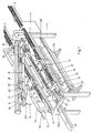
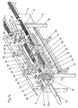
- the device shown in FIG. 1 is intended for connection to two conveyor troughs 1 and 2 arranged parallel to one another, each with a counting device 3 and 4 for the disks to be transferred along the conveyor troughs 1 and 2 into the device shaped workpieces are equipped.
- the disk-shaped workpieces are lids which are divided into strands of the same number and are to be wrapped in a wrapping of paper with an end closure of this wrapping in the device according to FIG. 1.
- the device according to FIG. 1 has a frame-shaped or table-shaped frame 5, on which receptacles 6 and 7, which run in the longitudinal direction of the frame 5, are provided in the respective extension of the conveyor troughs 1 and 2 for feeding the cover to be wrapped.
- a height-pivotable pressure beam 8 is articulated on a transverse side of the frame 5, which extends longitudinally centrally between the receiving grooves 6 and 7 and which in the direction of the double arrow 9 from the position shown in FIG lowered position parallel to the receptacles can be transferred.
- the wrapping station designated overall by 10
- the wrapping station in which the cover strands respectively removed from the receptacles 6 and 7 are wrapped in the covering. 1, a cover strand 11 can be seen in the wrapping station.
- the wrapping station 10 has two support rollers 12 and 13 which can be driven about its longitudinal axis and which, apart from the rotary movement, are held stationary in the frame 5.
- To transfer the cover strands from the receptacles 6 and 7 to the drivable Support rolls 12 and 13 of the wrapping station 10 are assigned to the receptacles on both sides of the respective strand, mutually movable clamping rails 14 and 15.
- the clamping rails 14 and 15 are each connected to actuating devices 16 and 17, with the aid of which they are moved into the clamping and release position and into a position above the receiving grooves 6 and 7 and from this raised position in the direction of the wrapping station 10 and there up to the drivable support rollers 11 and 12 can be lowered.
- the individual strands 11 can thus be removed from the receptacles, temporarily into a raised parking or Waiting position and be transferred from this to the drivable support rollers 12 and 13 of the wrapping station 10.
- the actuating devices 16 and 17 are equipped in a manner known per se with pneumatically actuatable drive elements which bring about the lifting and lateral displacement movement of the clamping rails 14 and 15.
- the sides of the clamping rails 14, 15 facing the respective cover strand 11 are expediently equipped with a non-slip and elastic coating in order to securely grasp all the covers of a strand and to be able to transfer them to the wrapping station 10 while maintaining the mutual position of the covers.
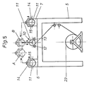
- the cover strand 11 gripped by the clamping rails 14 and 15 in the left part of FIG. 5 is first transferred to the raised position A. This position is at the same time an intermediate and waiting position, during which the associated receiving channel 6 is already free for receiving a next strand of cover.
- the cover strand 11 can then be transferred from position A to position B above the wrapping station before the lowering onto the drivable support rollers 12 and 13 takes place.
- the sequence of movements is indicated by arrows in FIG. 5.
- the return movement of the clamping rails 14 and 15 is reversed.
- the movement of the clamping rails 14 and 15 shown in the right-hand part of FIG. 5 is carried out analogously, so that the cover strands 11 can be removed from the receptacles 6 and 7 and transferred to the wrapping station 10 in the current change or in any sequence.
- the pressure bar 8 is equipped on its underside with paper guide plates 18 running in its longitudinal direction, between which at least one pressure roller 19 also running in the longitudinal direction of the pressure bar 8 is provided. In the lowered position of the pressure bar 8, the pressure roller 19 extends parallel to the drivable support rollers 12 and 13.
- a slide 20 which can be moved along this bar and which is equipped with folding fingers 21 which can be moved into a closed and a spreading position.
- a lockable abutment 22 is provided on an end face of the frame 5 see which is also equipped with folding fingers 21 like the slide 20.
- the folding fingers 21 are used in a manner yet to be described to form closure rosettes which arise towards the end of the wrapping process by transferring the folding fingers 21 into the closed position while simultaneously rotating the strand 11 already in the wrapping.
- a supply roll 23 of the web-shaped wrapping paper 24 is held in an unwinding device, generally designated 25.
- the web-shaped paper 24 is drawn off from the supply roll 23 by means of take-off rolls which are not shown in FIG. 1 and is guided between the drivable pressure rolls 12 and 13 with the aid of a feed device to be described later and under the action of the paper guide plates 18 and the pressure roll 19 around the respective one Strand 11 wrapped around in the wrapping station.
- a longitudinal cutting device 26 is provided, which is shown only schematically in FIG. 1 as a cutting wheel which can be moved transversely to the paper web 24.
- a gluing device 27 is provided to form the closure of the paper web wound around the respective strand 11, which in the example shown is designed as a nozzle bar 27 that can be moved back and forth across the paper web 24.
- the frame 5 In the area of the movable carriage 20 provided on the pressure beam 8, the frame 5 is in the directly below the drivable support rollers 12 and 13, a further slide 28 is held on a corresponding guide 28a running along the frame 5, which can be coupled to the slide 20 guided thereon in the lowered position of the pressure bar 8.
- the carriage 20 is equipped with a coupling pin 29 which engages in a corresponding bore 30 in the carriage 28.
- the carriage 28 is equipped with a device (not shown in FIG. 1 for the sake of clarity) for trimming the edge of the wrapping paper 24 and with an overall device 31 for applying the sealing tape and an associated cutting device.
- a device not shown in FIG. 1 for the sake of clarity
- an overall device 31 for applying the sealing tape and an associated cutting device.
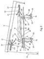
- FIG. 2 The devices for applying the sealing adhesive tape with the associated cutting devices can be seen from FIG. 2 in a schematic representation.
- the parts corresponding to FIG. 1 are also provided with the same reference numerals.
- Fig. 2 is indicated by the piston-cylinder arrangement 32 only in principle that the pressure bar 8 is transferred along the double arrow 9 in the raised or lowered position and can be brought into effect with a predetermined pressure on the lid stack 11 to be wrapped.
- FIG. 2 shows that a downward-pointing guide rod 33 is held on the slide 28 below the wrapping station 10 and holds a liftable and lowerable carrier 34 for an adhesive sealing tape roll 35.
- An adhesive tape holding plate 36 extends from the carrier 34 and runs parallel to the guide rod 33, which can be transferred with the carrier 34 when it is displaced along the guide rod 33 into a position directly in front of the end face 11a of the cover strand 11 which has already been wrapped and provided with a rosette, and back into the position shown in Fig. 2 is retractable.
- a device consisting of the same parts 33 to 36 is provided for applying the sealing adhesive tape, the downwardly projecting guide rod 33 with a guide piece for the slide 28, which is held stationary during operation of the device on the guide 28a 37 is connected.
- the cutting devices provided for cutting off the sealing adhesive tape are only indicated as knives 38 which can be moved transversely to the adhesive tape 39.
- FIG. 2 also shows that the carriage 28 is equipped with a device for trimming the edge of the paper web 24 on the carriage side.
- a co-rotating cutting knife 40 is provided in the carriage 28 on a drivable shaft 59 running along the carriage.
- a perforation knife 41 which rotates with this shaft is arranged on the shaft 59 and cuts an all-round perforation 42 into the paper web wound on the strand 11 at a distance and parallel to the trimmed edge of the paper web 24.
- Fig. 2 shows that both in the carriage 20 held longitudinally on the pressure beam 8 and in the abutment 22 each have a pressure limiting button 43, the pressure limiting button 43 in the carriage 20 pushing the carriage 20 against each other the drivable support rollers 12 and 13 located lid stack 11 determined.
- the pressure limiting button 43 of the fixed abutment 22 is subjected to a higher pressure than the pressure limiting button 43 of the slide 20, so that it acts practically like a stationary abutment.
- the pressure limit button 43 in the slide 20 exerts the same pressure on the lid stack 11 regardless of its length, so that the lid stacks to be wrapped each have the same packing density and, with larger thickness tolerances, the lid 11 is correspondingly longer or shorter.
- the cutting device in the carriage 28 ensures that, irrespective of the length of the respective stacks, the edge of the paper web 24 lying in the region of the carriage 28 is trimmed to such an extent that rosette formation is still possible.
- the perforation line 42 is also incised at the same distance from the end of the stack of covers.
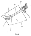
- the cutting device for trimming the edge of the paper web 24 is shown in an enlarged view in FIG. 4, but without the carriage 28 surrounding it or receiving it. Again, the same parts are provided with the same reference numerals.
- the paper web 24 is passed between two driven shafts 59 and 59a, a toothed belt drive 44 being used to drive the shafts 59 and 59a.
- the associated drive motor can be provided on or in the slide 28, for example in the form of a hydraulic motor.
- the feeding of the paper web 24 from the supply roll 23 to the lid stack 11 is shown schematically in enlarged form in FIG. 3.
- the web 24 is guided over a deflection roller 45 and between driven cooperating pull rollers 46 and 47 and further rollers 46a and 47a. Baffles not shown in the drawing are provided between the aforementioned pairs of rollers.
- the cutting device provided for cutting off the web sections has a cutting bar 48 which interacts with the cutting wheel 26.
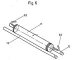
- the respective cover strands 11 transferred into the wrapping station 10 are after their transfer into the wrapping station 10 is acted upon by blow nozzles on its end faces until the pressure limiting buttons 43 come into contact, as is shown in FIG. 6 for a strand 11 located on the drivable support rollers 12 and 13 through the nozzles 65.
- the nozzles 65 can be held longitudinally displaceably on the pressure bar in order to adjust them to the respective length of the strand 11.
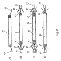
- FIG. 7 represents the individual phases of wrapping in a purely schematic manner.
- the cover strand 11 is acted on by the nozzles 65 on the end faces, as shown in FIG. 6, in such a way that the ends of the cover cannot fall over.
- the slide 20 with its folded fingers 21 advanced with its advanced pressure limiting button 43 against the strand 11 and pressed it against the pressure limiting button 43 of the abutment 22, so that it transferred into the correct position with respect to the paper web 24 and while maintaining an axial pressure is wrapped by feeding the paper web 24, as shown in phase c.
- the folding fingers 21 are now transferred into the closed position in accordance with phase d, the folding fingers interacting with the end projection of the covering in such a way that a rosette is folded.
- the pressure limiting buttons 43 are moved back into their starting position.
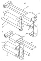
- sealing tape 39 is shown in the form of a partial illustration from FIG. 2 in an enlarged view and for two different positions of the adhesive tape holding plates 36 in FIGS. 8 and 9.
- FIG. 8 and 9 show the device for applying the sealing adhesive tape 39 in the area of the abutment 22 in FIG. 2.
- the adhesive tape holding plate 36 is shown in its lower starting position.
- the adhesive tape holding plate 36 has nozzle openings 36a, which are connected to a collecting channel 36b, which in turn is connected to a line 36c, via which a compressed air or suction air source can be connected.
- the nozzle openings 36a are suctioned, so that the section of the sealing tape 39 located in front of the holding plate 36 is pressed against the holding plate 36.
- the sealing tape 39 is coated on its side facing away from the holding plate 36 with adhesive.
- the section of the sealing tape 39 extending above the holding plate 36 adheres with its adhesive layer to the front rosette of the wrapping of the cover stack 11.
- the cover strand 11 provided with the covering is at rest, ie it is no longer set in rotation by the drivable support rollers 12 and 13.
- the sealing adhesive tape 39 has been applied to the front ends of the wrapped lid stacks 11, the respectively finished lid stack is pushed out of the wrapping station 10 in the longitudinal direction from the device according to FIG. 1 and thereby reaches a discharge channel 66 according to FIG. 1.
- the adhesive tape holding plate 36 is transferred from the position shown in FIG. 8 while maintaining the suction at the nozzle openings 36a into the position shown in FIG. 9 and In this position, compressed air is then applied instead of the suction of the nozzle openings 36a, as is indicated by the arrows in FIG. 9. In this way, the section of the sealing tape 39 located in front of the holding plate 36 is pressed against the rosette and fixes it. The upper end of the adhesive tape section 39 is already folded over in the direction of the cover strand. 8, a further section of the adhesive tape 39 is pulled off the roll 35 and the section in front of the holding plate 36 is again acted upon by suction air via the nozzle openings 36a, as is the case in connection with 8 has already been described.
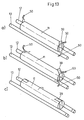
- the pressure bar 8 or the movable carriage 20 can pivot from top to bottom 10 can be provided with rollers 68 which can be moved diametrically over the strand ends and which are held on a carriage 69 which in turn can be moved back and forth along the support 67.
- phase a namely the starting position of the resilient pressure rollers 68
- phase b is shown in the lower part, in which the pressure rollers 68 roll the protruding ends of the sealing adhesive tape 39 onto the peripheral surface of the wrapping of the strand 11 to have.
- FIG. 11 A schematic representation of how the circumferentially loose covering of the cover strands 11 is achieved, which is desirable in order to be able to remove the cover easily from the cover after opening, is illustrated in FIG. 11.
- phase a in the left part of FIG. 11 the start of the winding of the strand 11 is shown, in the right part phase b immediately before the end of the wrapping process.
- the cover strand 11 lies in the wrapping station 10 on the drivable support rollers 12 and 13, on which it is pressed by the pressure roller 19 of the lowered pressure bar 8.
- the paper web 24 for wrapping the stack 11 is guided along the guide plates 70 and 71 shown in FIG. 11 and through the drivable roller pair 46a and 47a into the gap between the drivable support roller 12 and the stack 11.
- the supplied paper web 24 slides in the area outside the support or pressure rollers 12, 13 and 19 along the inner wall surfaces of the paper guide plates 18, so that a loose wrapping is produced, as shown in phase b in the right part of FIG. 11 .
- a feed device for the strand 11 consisting of the counted lids is controllable by the counting devices 3 and 4 in connection with a facility device for inserting spacers is provided, which is shown schematically in Fig. 12 and partly in Fig. 1.
- the counting device 3 shown there is provided with a feed device 51 which can be controlled by it and which, when the desired number is reached, advances the lid of a stack 11 in the manner indicated, so that a gap 52 is created between the stack 11 and the subsequent lid.
- a feed device 51 which can be controlled by it and which, when the desired number is reached, advances the lid of a stack 11 in the manner indicated, so that a gap 52 is created between the stack 11 and the subsequent lid.
- one or more cylindrical spacers are introduced, which are smaller in diameter than the lid, so that they are not detected when the lid stack 11 is transferred from the receiving channel 6 or 7 into the wrapping station 10.
- the spacers 53 thus remaining in the receiving channel 6 or 7 are returned from the end of the receiving channel 6 or 7 back into the area of the gap 52.
- a pipeline 54 running above and at a distance parallel to the respective receiving channel 6 or 7 is provided, which is connected to connecting shafts 55 and 56.
- the spacers 53 arriving at the end of the receiving channel 6 or 7 are transferred into the pipeline 54 via a piston-cylinder arrangement 57 and conveyed there by a further piston-cylinder arrangement 58 in the direction of the beginning of the receiving channel 6 or 7, as indicated by arrows is.
- Controllable retainers in the form of piston-cylinder arrangements are provided in the connecting shaft 56, which are actuated by the feed device 51, so that one or more spacers 53 are released for falling into the gap 52 after the gap 52 has been formed.
- the device shown schematically in FIG. 2 is also partially recognizable in FIG. 1 above the receiving channel 6.
- 14 and 15 show a variant of the arrangement according to FIG. 1, the difference essentially consisting in the fact that in the arrangement according to FIGS. 14 and 15 there is no pressure bar with the elements held thereon. 14 and 15, the parts corresponding to the other figures are also provided with the same reference numerals.
- lifting and lowering support arms 60 are provided in the embodiment according to FIGS. 14 and 15, on which the pressure roller 19 and the paper guide plates 18 are held.
- the support arms 60 are held in the manner of cantilever arms on lifting or guide rods 62 which, in the example shown, are fastened via intermediate pieces 63 to the pipeline 54 running parallel to the receiving channel 6 for the return of the spacers 53.
- the support arms 60 extend in the manner of cantilevers up to the wrapping station 10 and can be moved so far in the direction of the double arrows along the vertical bars or together with them that the pressure roller 19 on the cover strand 11 located in the wrapping station 10 in the lowered position rests and in the raised position the supply of a further strand of cover from one of the receptacles 6 and 7 by means of the mutually movable clamping rails 14 and 15 is not hindered in the manner described above.
- the paper guide plates 18 held on the support beams are simultaneously formed as gripping shells in the device according to FIGS. 14 and 15 and are connected to an actuating device not shown in the figures, so that they come from a position in which they surround the strand to be wrapped at a distance. can be transferred into a clamping position in order to capture the strand which is respectively wrapped in the wrapping station 10 and provided with the fastening tapes applied on the end face and to be transferred to the raised position during the upward movement of the support arms 60. Since in this raised position the sealing tape ends are to be rolled on, in alignment with the strand in its raised position, the longitudinally displaceable resilient rollers 68, which are pivotably held on the pressure bar 8 in FIG. 1, are held in a stationary slide guide 64 and can be held by means of one in the drawing not shown drive in the direction of the double arrows with their resilient rollers 68 in the manner previously described for rolling the sealing tape ends over the strand ends and back.
- the closure tape adhesive tape ends are no longer rolled in the wrapping station 10, but in a position of the wrapped cover strand above this wrapping station.
- the wrapping station can be loaded with a new cover strand while the sealing tape ends are being rolled on.
- swivels are pivotable under the cover strand which is in the raised position Tabs 61 are provided, via which after the release of the cover strand by spreading the paper guide plates 18, the strand can roll laterally and above the wrapping station 66, which deviates from FIG. 1 and from which it is conveyed further by means of an ejection device, not shown.
- the movable slide 20 provided on the pressure bar in FIG. 1 is structurally combined with the slide 28 in the embodiment according to FIGS. 14 and 15 and forms the component 20a shown in FIG. 14, which like the slide 20 with the folding fingers 21 and a pressure limiting button is equipped, as has already been described in connection with the slide 20.
- FIG. 15 shows a schematic representation of the upper position of the support arms 60 as well as the arrangement of the inclined tabs 61 and the discharge channel provided laterally above the wrapping station 10.
- the inclined tabs 61 are articulated on the discharge trough 66. It can be seen from FIG. 15 that when the support arms 60 are in the raised position, the wrapping station 10 can be easily loaded with a new strand from one of the receptacles 6 and 7, respectively.
- the individual movement sequences and their sequence are controlled by electronics not shown in the drawing, piston-cylinder arrangements being predominantly provided for driving the individual elements of the device to be moved, but the device is not restricted to the use of these drive elements.
Landscapes
- Engineering & Computer Science (AREA)
- Mechanical Engineering (AREA)
- Packaging Of Special Articles (AREA)
- Basic Packing Technique (AREA)
- Package Closures (AREA)
Applications Claiming Priority (2)
| Application Number | Priority Date | Filing Date | Title |
|---|---|---|---|
| DE19873729271 DE3729271A1 (de) | 1987-09-02 | 1987-09-02 | Vorrichtung zum verpacken zylindrischer straenge aus einer vielzahl scheibenfoermiger werkstuecke |
| DE3729271 | 1987-09-02 |
Publications (2)
| Publication Number | Publication Date |
|---|---|
| EP0305956A2 true EP0305956A2 (fr) | 1989-03-08 |
| EP0305956A3 EP0305956A3 (fr) | 1990-03-21 |
Family
ID=6335030
Family Applications (1)
| Application Number | Title | Priority Date | Filing Date |
|---|---|---|---|
| EP88114083A Withdrawn EP0305956A3 (fr) | 1987-09-02 | 1988-08-30 | Dispositif pour emballer des barres cylindriques composées d'une pluralité de pièces discoides |
Country Status (4)
| Country | Link |
|---|---|
| US (1) | US4848059A (fr) |
| EP (1) | EP0305956A3 (fr) |
| CA (1) | CA1297777C (fr) |
| DE (1) | DE3729271A1 (fr) |
Cited By (3)
| Publication number | Priority date | Publication date | Assignee | Title |
|---|---|---|---|---|
| EP0495580A1 (fr) * | 1991-01-16 | 1992-07-22 | Fleetwood Systems, Inc. | Machine de comptage et d'ensachage pour des articles amenés par plusieurs rangées |
| FR2715371A1 (fr) * | 1994-01-21 | 1995-07-28 | Sppr | Procédé et machine automatique d'enveloppage de blocs de produits alimentaires gras (foie gras par exemple) sous film aluminium par exemple. |
| EP0688719A1 (fr) * | 1994-06-20 | 1995-12-27 | Pakenso Oy | Procédé et dispositif pour emballer des disques de front en carton pour rouleaux de papier et un emballage |
Families Citing this family (13)
| Publication number | Priority date | Publication date | Assignee | Title |
|---|---|---|---|---|
| US5175980A (en) * | 1988-09-30 | 1993-01-05 | Sardee Industries, Inc. | Apparatus and method for packaging groups of articles |
| US4967537A (en) * | 1989-10-26 | 1990-11-06 | Adolph Coors Company | Apparatus for packaging articles |
| US5005340A (en) * | 1989-12-21 | 1991-04-09 | Fleetwood Systems, Inc. | Apparatus for inspecting and packaging can ends |
| US5471822A (en) * | 1991-09-30 | 1995-12-05 | Coors Brewing Company | Apparatus and method for packaging articles |
| US5617704A (en) * | 1992-09-15 | 1997-04-08 | Ferag Ag | Method of forming a tubular pack of printed products with a transparent foil cover |
| US5533321A (en) * | 1995-08-09 | 1996-07-09 | Lamb-Grays Harbor Co. | Method and apparatus for wrapping, crimping and heading paper rolls at a single station |
| US5685129A (en) * | 1996-06-14 | 1997-11-11 | Metal Container Corporation | Automatic can lid bag sealer |
| ES2246638B1 (es) * | 2003-05-06 | 2007-04-01 | Taller Autorema, S.L. | Maquina embolsadora automatica de tapas basicas y de facil apertura en bolsas de papel autoencolante. |
| EP1559650B1 (fr) * | 2004-01-23 | 2007-02-28 | Taller Autorema, s.l. | Dispositif d'emballage automatique de couvercles dans des sachets autocollants |
| NL1028793C2 (nl) * | 2005-04-18 | 2006-10-20 | Celema B V | Inrichting voor het in verticale richting transporteren van een reeks achter elkaar geplaatste losse voorwerpen. |
| WO2009057985A1 (fr) * | 2007-11-01 | 2009-05-07 | Technicolor Mexicana, S. De R. L. De C. V. | Machine d'emballage et procédé d'emballage de disques optiques avec un film étirable |
| CN110194287B (zh) * | 2019-06-10 | 2024-11-22 | 苏州真荃材料有限公司 | 自动卷膜机 |
| CN112046822B (zh) * | 2020-09-08 | 2024-11-12 | 格力电器(武汉)有限公司 | 外包装备料装置及包装装置 |
Family Cites Families (14)
| Publication number | Priority date | Publication date | Assignee | Title |
|---|---|---|---|---|
| FR462561A (fr) * | 1912-09-19 | 1914-01-30 | Sapal Plieuses Automatiques | Machine à empaqueter des corps en forme de rondelles ou des objets cylindriques |
| DE501574C (de) * | 1927-07-16 | 1930-07-07 | Mills Novelty Company | Maschine zur Umwicklung von kleinen Gegenstaenden |
| DE719595C (de) * | 1939-05-11 | 1942-06-18 | Heinrich Dahlhaus | Verfahren und Vorrichtung zum Verpacken scheibenfoermiger Gegenstaende, wie Tabletten aus Zucker, Pfefferminz o. dgl. |
| US3899864A (en) * | 1972-12-15 | 1975-08-19 | Laurel Bank Machine Co | Coin wrapping apparatus |
| JPS5819530B2 (ja) * | 1978-09-22 | 1983-04-19 | ロ−レルバンクマシン株式会社 | 硬貨包装機の包装紙セツト方法 |
| US4221103A (en) * | 1978-11-20 | 1980-09-09 | Laurel Bank Machine Co., Ltd. | Packaging paper cutting mechanism for coin packaging machine |
| US4417435A (en) * | 1979-02-24 | 1983-11-29 | Daiwa Can Company | Apparatus for automatically packing end closures for cans in paper bags |
| US4395864A (en) * | 1981-01-28 | 1983-08-02 | American Can Company | Apparatus for the automatic counting and bagging of can ends |
| DE3334769A1 (de) * | 1983-09-26 | 1985-04-11 | Karges-Hammer-Maschinen Gmbh & Co Kg, 3300 Braunschweig | Transportbehaelter sowie verfahren und vorrichtung zum transportieren von dosendeckelstapeln in dem transportbehaelter |
| US4537550A (en) * | 1983-09-29 | 1985-08-27 | Fleetwood Systems, Inc. | Automatic stack developing and loading system |
| JPS61152518A (ja) * | 1984-12-25 | 1986-07-11 | 友和産業株式会社 | 円筒物端面包装装置 |
| US4651500A (en) * | 1985-02-14 | 1987-03-24 | Valley Tissue Packaging, Inc. | Method and apparatus for wrapping rolls of paper |
| JPH059284Y2 (fr) * | 1985-03-20 | 1993-03-08 | ||
| NL8501520A (nl) * | 1985-05-28 | 1986-12-16 | Thomassen & Drijver | Inrichting en werkwijze voor het verpakken van een rij schijfvormige elementen, en de vervaardigde verpakking. |
-
1987
- 1987-09-02 DE DE19873729271 patent/DE3729271A1/de not_active Withdrawn
-
1988
- 1988-08-30 EP EP88114083A patent/EP0305956A3/fr not_active Withdrawn
- 1988-08-31 CA CA000576199A patent/CA1297777C/fr not_active Expired - Lifetime
- 1988-09-02 US US07/240,256 patent/US4848059A/en not_active Expired - Fee Related
Cited By (4)
| Publication number | Priority date | Publication date | Assignee | Title |
|---|---|---|---|---|
| EP0495580A1 (fr) * | 1991-01-16 | 1992-07-22 | Fleetwood Systems, Inc. | Machine de comptage et d'ensachage pour des articles amenés par plusieurs rangées |
| FR2715371A1 (fr) * | 1994-01-21 | 1995-07-28 | Sppr | Procédé et machine automatique d'enveloppage de blocs de produits alimentaires gras (foie gras par exemple) sous film aluminium par exemple. |
| EP0688719A1 (fr) * | 1994-06-20 | 1995-12-27 | Pakenso Oy | Procédé et dispositif pour emballer des disques de front en carton pour rouleaux de papier et un emballage |
| US5706945A (en) * | 1994-06-20 | 1998-01-13 | Pakenso Oy | Method and an apparatus for packing cardboard end covers of paper rolls and a package |
Also Published As
| Publication number | Publication date |
|---|---|
| US4848059A (en) | 1989-07-18 |
| CA1297777C (fr) | 1992-03-24 |
| DE3729271A1 (de) | 1989-03-23 |
| EP0305956A3 (fr) | 1990-03-21 |
Similar Documents
| Publication | Publication Date | Title |
|---|---|---|
| DE3243994C2 (de) | Wickelmaschine zum Aufwickeln einer längsgeteilten Bahn | |
| DE2930474C2 (de) | Doppeltragwalzentwickelmaschine | |
| DE1278327B (de) | Vorrichtung zum Stapeln und Einwickeln von Muenzen, Spielmarken od. dgl. in eine Folie | |
| DE3729271A1 (de) | Vorrichtung zum verpacken zylindrischer straenge aus einer vielzahl scheibenfoermiger werkstuecke | |
| CH649267A5 (de) | Verfahren und vorrichtung zum einbringen wenigstens einer einlage in druckprodukte. | |
| DE3043507A1 (de) | Verfahren und vorrichtung zum herstellen von paeckchen gefalteter und ineinandergeschossener papierblaetter | |
| DE1532830B1 (de) | Verfahren und Maschine zum fortlaufenden Herstellen von Tragtaschen | |
| DE2542124A1 (de) | Einrichtung zum stapeln von kontinuierlich, insbesondere in einer schuppenformation auf einer foerderbahn anfallenden druckprodukten | |
| DE2906598A1 (de) | Vorrichtung zur bewerkstelligung eines fliegenden rollenwechsels | |
| EP0143930B1 (fr) | Procédé de fabrication de brosses et machine pour la mise en oeuvre du procédé | |
| EP0432592B1 (fr) | Dispositif d'emballage de cigarettes | |
| DE4122692A1 (de) | Einwickelmaschine fuer im wesentlichen parallelflache schachtelfoermige elemente | |
| AT404538B (de) | Vorrichtung zur herstellung von wickeln aus teigblättern und trennblättern | |
| DE2624812A1 (de) | Einwickelmaschine | |
| DE60200291T2 (de) | Umwickelmaschine mit Flanken zum Tragen von sich entlang einer geschlossenen Bahn bewegenden greifenden Zentrierdornen | |
| DE29917881U1 (de) | Umreifungsmaschine zum Umreifen eines Gutstapels | |
| DE2553612B2 (de) | Verfahren und Vorrichtung zum Eintaschen von Filmabschnitten | |
| DE69403131T2 (de) | Automatischer Rollenwechsler für Verpackungsmaterialbahnen | |
| DE1112392B (de) | Vorrichtung zum Zufuehren von Wickelkernen in einer Papierwickelmaschine | |
| DE1561434C3 (de) | Verfahren zum fortlaufenden Herstellen von Tragtaschen oder -beuteln mit zwei Traggriffen und Maschine zum Ausüben des Verfahrens | |
| DE2629381C3 (de) | Verfahren zur kontinuierlichen Herstellung von Tamponrohlingen und Vorrichtung zur Durchführung des Verfahrens | |
| EP1451087B1 (fr) | Dispositif d'enroulement continu de bandes | |
| DE2414564C3 (de) | Vorrichtung zum Quertrennen von kontinuierlich ablaufenden, in Abständen zur Ausbildung von AbreiBschwächungsUnien quer perforierten Werkstoffbahnen | |
| DE2537692A1 (de) | Verfahren und vorrichtung zum vollautomatischen befuellen einer faltschachtel mit flaschen o.dgl. | |
| DE449485C (de) | Verfahren und Vorrichtung zur Herstellung von Fliegenfaengern in Bandrollenform |
Legal Events
| Date | Code | Title | Description |
|---|---|---|---|
| PUAI | Public reference made under article 153(3) epc to a published international application that has entered the european phase |
Free format text: ORIGINAL CODE: 0009012 |
|
| AK | Designated contracting states |
Kind code of ref document: A2 Designated state(s): BE DE FR GB IT LU NL SE |
|
| PUAL | Search report despatched |
Free format text: ORIGINAL CODE: 0009013 |
|
| AK | Designated contracting states |
Kind code of ref document: A3 Designated state(s): BE DE FR GB IT LU NL SE |
|
| 17P | Request for examination filed |
Effective date: 19900625 |
|
| 17Q | First examination report despatched |
Effective date: 19920512 |
|
| STAA | Information on the status of an ep patent application or granted ep patent |
Free format text: STATUS: THE APPLICATION IS DEEMED TO BE WITHDRAWN |
|
| 18D | Application deemed to be withdrawn |
Effective date: 19921229 |