EP0305995A2 - Un répétiteur-amplificateur optique - Google Patents
Un répétiteur-amplificateur optique Download PDFInfo
- Publication number
- EP0305995A2 EP0305995A2 EP88114195A EP88114195A EP0305995A2 EP 0305995 A2 EP0305995 A2 EP 0305995A2 EP 88114195 A EP88114195 A EP 88114195A EP 88114195 A EP88114195 A EP 88114195A EP 0305995 A2 EP0305995 A2 EP 0305995A2
- Authority
- EP
- European Patent Office
- Prior art keywords
- optical
- signal light
- semiconductor laser
- amplifying
- optical semiconductor
- Prior art date
- Legal status (The legal status is an assumption and is not a legal conclusion. Google has not performed a legal analysis and makes no representation as to the accuracy of the status listed.)
- Granted
Links
Images


Classifications
-
- H—ELECTRICITY
- H04—ELECTRIC COMMUNICATION TECHNIQUE
- H04B—TRANSMISSION
- H04B10/00—Transmission systems employing electromagnetic waves other than radio-waves, e.g. infrared, visible or ultraviolet light, or employing corpuscular radiation, e.g. quantum communication
- H04B10/29—Repeaters
- H04B10/291—Repeaters in which processing or amplification is carried out without conversion of the main signal from optical form
- H04B10/293—Signal power control
- H04B10/2931—Signal power control using AGC
-
- H—ELECTRICITY
- H01—ELECTRIC ELEMENTS
- H01S—DEVICES USING THE PROCESS OF LIGHT AMPLIFICATION BY STIMULATED EMISSION OF RADIATION [LASER] TO AMPLIFY OR GENERATE LIGHT; DEVICES USING STIMULATED EMISSION OF ELECTROMAGNETIC RADIATION IN WAVE RANGES OTHER THAN OPTICAL
- H01S5/00—Semiconductor lasers
- H01S5/50—Amplifier structures not provided for in groups H01S5/02 - H01S5/30
- H01S5/5009—Amplifier structures not provided for in groups H01S5/02 - H01S5/30 the arrangement being polarisation-insensitive
- H01S5/5018—Amplifier structures not provided for in groups H01S5/02 - H01S5/30 the arrangement being polarisation-insensitive using two or more amplifiers or multiple passes through the same amplifier
-
- H—ELECTRICITY
- H04—ELECTRIC COMMUNICATION TECHNIQUE
- H04B—TRANSMISSION
- H04B10/00—Transmission systems employing electromagnetic waves other than radio-waves, e.g. infrared, visible or ultraviolet light, or employing corpuscular radiation, e.g. quantum communication
- H04B10/29—Repeaters
- H04B10/291—Repeaters in which processing or amplification is carried out without conversion of the main signal from optical form
- H04B10/2912—Repeaters in which processing or amplification is carried out without conversion of the main signal from optical form characterised by the medium used for amplification or processing
- H04B10/2914—Repeaters in which processing or amplification is carried out without conversion of the main signal from optical form characterised by the medium used for amplification or processing using lumped semiconductor optical amplifiers [SOA]
-
- H—ELECTRICITY
- H01—ELECTRIC ELEMENTS
- H01S—DEVICES USING THE PROCESS OF LIGHT AMPLIFICATION BY STIMULATED EMISSION OF RADIATION [LASER] TO AMPLIFY OR GENERATE LIGHT; DEVICES USING STIMULATED EMISSION OF ELECTROMAGNETIC RADIATION IN WAVE RANGES OTHER THAN OPTICAL
- H01S5/00—Semiconductor lasers
- H01S5/06—Arrangements for controlling the laser output parameters, e.g. by operating on the active medium
- H01S5/068—Stabilisation of laser output parameters
- H01S5/0683—Stabilisation of laser output parameters by monitoring the optical output parameters
Definitions
- the invention relates to an optical amplifying repeater for optical communication use, and more particularly to an optical repeater in which a signal light is directly amplified without conversions between optical and electric signals.
- a signal light is inevitably attenuated and is circumvented a waveform distortion when propagating through an optical fiber transmission line due to the transmission loss and chromatic dispersion of the fiber, respectively.
- a predetermined number of repeaters with predetermined intervals are required to be construct a long distance optical communication system, so that the optical power and the waveform of signal light are recovered to their initial stages.
- the conventional repeater for the optical communication system described above has disadvantages, such that a probability for fault is high therein, a reliability thereof is low, a system size is large, and a system cost is high because a number of electrical devices are used in the repeater for the signal processing.
- an optical amplifying repeater in which the signal light is directly amplified without conversion between optical and electric signals is studied, for instance, as described on pages 51 to 62 of "Journal of Optical Communications, Vol. 4, 1983", and on pages 253 to 255 of "Electronics Letters, Vol. 22, 1986".
- the optical amplifying repeater is suitably applicable to an optical communication system in which waveform reshaping of the signal light is not under parameters, for instance, that the bit rate is lower than several hundreds M bps and the transmission length is less than 1000 km.
- optical amplifying repeater such as a Fabry-Perot type or a distributed feedback semiconductor laser which operate with a bias current below its oscillation threshold, and a travelling wave type semiconductor laser having anti-reflection coatings of a reflectivity less than several percents on both facets.
- the signal light is amplified in the active layer by the stimulated emission effect.
- the polarization dependent gain of the semiconductor laser amplifier described above it is difficult to propagate the signal light through the optical fiber such that polarization of the signal light is maintained to be constant in the optical fiber communication system. Furthermore, the polarization of the signal light is easily changed when unexpected external disturbance is applied to the optical fiber. For this reason, the optical power level of the signal light after amplification is fluctuated dependent on the polarization of input signal light in a case where one of the conventional optical semiconductor laser amplifiers is applied to the optical amplifying repeater.
- a polarization controller is provided on the input side of the optical semiconductor laser amplifier.
- the polarization controller presently available is not suitable for this application because it has a loss of more than several dB, and the long term stability thereof is still insufficient for such a long term use.
- the conventional optical amplifying repeater is required to be improved in regard to a stability and a reliability, which are presently poor due to the aforementioned amplification gain fluctuation of the optical semiconductor laser amplifiers in accordance with both the atmospheric temperature change and the polarization change of the signal light. Furtheremore, there is another problem for the conventional optical amplifying repeater that the transmission line is broken down when the optical semiconductor laser amplifier is damaged during the long term use.
- an optical amplifying repeater comprises a plurality of optical amplifiers, a monitor unit and a control circuit.
- An input signal light propagated through a first optical fiber is divided by an optical divider to be supplied to the plurality of the optical amplifiers.
- the divided signal lights are individually amplified.
- the amplified signal lights are then combined by an optical coupler to be supplied as an output signal light to a second optical fiber.
- the monitor unit detects a optical power level of the output signal light
- the control circuit controls at least one of the optical amplifiers in its amplification gain so that the optical power level of the output signal light is maintained to be a predetermined value.
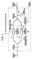
- Fig. 1 shows an optical amplifying repeater 10 in an embodiment according to the invention.
- the optical amplifying repeater 10 comprises optical semiconductor laser amplifiers 21 and 22, an optical coupler 11 for dividing a signal light propagated through an input optical fiber 61 into two signal lights supplied to two optical fibers 113 and 114, and an optical coupler 12 for combining two signal lights of two optical fibers 121 and 122 and for dividing a combined signal light into two signal lights supplied to an output optical fiber 62 and a monitor optical fiber 124.
- Each of the optical couplers 11 and 12 is of a structure in which two single mode optical fibers each having a core diameter of 10 ⁇ m are melted to be connected in parallel by a predetermined length, and a dividing ratio thereof is one to one (1:1) at a wavelength of 1.55 ⁇ m and the loss therein is less than 0.1 dB.
- Each of the semiconductor laser amplifiers 21 and 22 is of a travelling wave type semiconductor laser amplifier in which both facets of an InGaAsP/InP semiconductor laser is anti-reflection coated to have reflectivities below two percents.
- a photo-detector 3 is of a Ge photodiode and is provided to face the output of the monitor optical fiber 124 of the optical coupler 12.
- Each of the input and output optical fibers 61 and 62 is of a single mode optical fiber having a core diameter of 10 ⁇ m.
- Each end of the optical fiber couplers 113 and 114, and each end of the optical fiber couplers 121 and 122 are processed to be of spherical shapes with a radius of approximately 40 ⁇ m so that the ends thereof acts as lenses.
- the coupling loss between the optical fiber and the optical semiconductor laser amplifiers 21 and 22 is approximately 3 dB, respectively.
- the input and output optical fibers 61 and 62 are fusion-spliced to be connected to the optical couplers 11 and 12, respectively, with a splice loss of less than as small as 0.2 dB.
- a threshold current is 50.1 mA for a laser oscillation
- amplification gains for signal lights of TE and TM waves are shown in Fig. 2 at a wavelength of 1.55 ⁇ m.
- the amplification gains is 38 dB for TE wave and 30 dB for TM wave, respectively, when the injection current is 49.5 mA.
- the 1.55 ⁇ m signal light power propagated through the optical fiber 61 is -35 dBm at the input end of the optical coupler 11.
- the signal light is equally divided in the optical coupler 11 to be supplied to the optical semiconductor laser amplifiers 21 and 22 in which a signal light power is -41 dBm at the inputs thereof because the coupling loss thereof is 3 dB as described before.
- the optical semiconductor laser amplifier 21 is controlled to provide an amplification gain of 30 dB, while the optical semiconductor laser amplifier 22 is controlled to be under "off-state" with an injection current of "zero" so that a signal light power of -14 dBm is supplied from the optical semiconductor laser amplifier 21 to the optical fiber 121, while no signal light is supplied from the optical semiconductor laser amplifier 22 to the optical fiber 122. Therefore, the signal light power is regenerated to the level of up to -17 dBm, and the regenerated signal light is supplied through the optical coupler 12 to the output optical fiber 62.
- part of the signal light from the optical fiber 124 which is a level of -17 dBm, is detected by the photo-detector 3.
- the monitor signal from the photo-detector 3 is then supplied to a control circuit 4 by which power supplies 51 and 52 are controlled to supply predetermined injection currents to the optical semiconductor laser amplifiers 21 and 22, respectively.
- an amplification gain of the optical semiconductor laser amplifier 21 is maintained to be 30 dB even when the polarization state of the input signal light is changed due to propagation of the optical fiber 61.
- the output current of the power supply 51 is in a range from 48.5 mA to 49.5 mA.
- the control circuit 4 in a case where the monitor signal light level of the photo-detector 3 can not be maintained to be -17 dBm even if the injection current is increased up to 49.7 mA, due to accidents such as a deterioration of the optical semiconductor laser amplifier 21, it is controlled by the control circuit 4 that the injection current of the optical semiconductor laser amplifiers 21 is fixed to be 49.7 mA and the optical semiconductor laser amplifier 22, which is not operate under normal situation, begins to operate together with the optical semiconductor laser amplifier 21.
- signal light to the optical fiber 62 can be regenerated to the level of -17 dBm by the optical semiconductor laser amplifier 22, normally, even if the signal light path of the optical semiconductor laser amplified 21 is broken down due to the deterioration of the optical semiconductor laser amplifier 21. If it happens that both of the optical semiconductor laser amplifiers 21 and 22 are broken down due to the long term use, and thus the monitor signal light level can not be maintained to be -17 dBm, an alarm output signal is produced in the control circuit 4 and sent to an exterior circuit (not shown).
- Fig. 3 shows an optical semiconductor laser amplifier which can be applied to the optical amplifying repeater in the aforementioned embodiment.
- the optical semiconductor laser amplifiers includes optical semiconductor laser amplifying elements 35 and 36, a polarization beam splitter 31 for dividing an input signal light into two output signal lights having orthogonal polarizations each other, an optical mirror 32 for reflecting one of the two signal lights from the polarization beam splitter 31, lenses 33 and 34 for focussing the the two signal lights from the polarization beam splitter 31 and the signal light reflected by the optical mirror 32 on active layers 351 and 361 of the optical semiconductor laser amplifying elements 35 and 36 respectively, lenses 37 and 38 for collimating signal lights radiated from the optical semiconductor laser amplifying elements 35 and 36, an optical mirror 39 for reflecting the signal light collimated by the lens 38, and a polarization beam coupler 40 for combining the signal lights collimated by the lens 37 and reflected by the optical mirror 39 to produce an output signal light.
- each of the polarization beam splitter and coupler 31 and 40 is made of two glass prisms with right-angle triangle which is combined to the other by plane to plane together.
- Each of the optical semiconductor laser amplifying elements 35 and 36 is of an InGaAsP/InP travelling wave type semiconductor laser which facets are with anti-reflection films to have reflectivities of less than two percents.
- the optical semiconductor laser amplifying elements 35 and 36 have, respectively, the active layer 351, 361 with a thickness of approximately 0.1 ⁇ m, a width of approximately 1.5 ⁇ m and a length of approximately 300 ⁇ m.
- An amplification gain of the InGaAsP/InP travelling-wave type semiconductor laser amplifying element is different between TE and TM waves at a wavelength of 1.55 ⁇ m as explained in Fig. 2.
- Each of the lenses 33, 34, 37 and 38 is of the so-called selfoc lens (a rod lens) with a spherical shape at the tip thereof and having a focal length of 5 mm and a coupling loss of 3 dB, and each of the optical mirrors 32 and 29 is of a mirror made by an evaporation of Au, which reflectivity is 99%.
- an input signal light which is to be amplified in the optical semiconductor laser amplifying elements 35 and 36, having a wavelength of 1.55 ⁇ m is divided by the polarization splitter 31 into TE wave and TM wave.
- the TE wave is launched by the lens 33 to the active layer 351 of the optical semiconductor laser amplifying element 35 in which the TE wave is amplified, and the TM wave is reflected by the optical mirror 32 so that the TM wave is coupled by the lens 34 to the active layer 361 of the optical semiconductor laser amplifying element 36 in which the TM wave is amplified.
- the TE wave thus amplified in the optical semiconductor laser amplifying element 35 is supplied through the lens 37 to the polarization coupler 40, while the TM wave thus amplified in the optical semiconductor laser amplifying element 36 is supplied through the lens 38 to the optical mirror 39, thereby being reflected to be supplied to the polarization coupler 40.
- signal lights of the both polarization components are combined to be coupled as an amplified signal light to the optical fiber of a following stage.
- Amplification gains of the optical semiconductor laser amplifying elements 35 and 36 are controlled to be varied by adjusting injection currents supplied to current input terminals 352 and 362 thereof, respectively, in accordance with a monitor signal as explained in the embodiment.
- an input signal light is divided to be supplied to plural optical semiconductor laser amplifiers, and each of the signals is amplified independently. Also, amplification gain of each of the plural optical semiconductor laser amplifier is controlled to be varied in accordance with a monitor signal. Consequently, the optical power of the amplified signal light can be kept to predetermined value even if a polarization of the input signal light propagated through an optical fiber is changed due to the external disturbance applied to the optical fiber, and amplification gains of the optical semiconductor laser amplifiers are fluctuated due to the change of an atmospheric temperature.
- a transmission line is prevented from being broken down because the optical power of the output amplified signal light can be maintained to be a predetermined level by increasing an amplification gain of at least one optical semiconductor laser amplifier among the plural optical semiconductor laser amplifiers even if one of the plural optical semiconductor laser amplifiers is damaged.
- the input signal light is preferably divided into TE and TM waves as described before.
- the TE and TM waves are independently amplified in optical semiconductor laser amplifying elements and then combined.
- the amplified signal light which is obtained from the independent optical amplifications and the combination of each of amplified signal light components is ideally maintained to be a predetermined level even if the polarization state of the input signal light is extraordinarily changed.
- the input signal light power is P IN
- a TE wave component of the input signal light is a ⁇ P IN
- a TM wave component of the input signal light is (1 - a)P IN .
- G1 an amplification gain of an optical semiconductor laser amplifying element for amplifying TE wave
- G2 an optical semiconductor laser amplifying element for amplifying TM wave
- an amplified signal light power P OUT which is obtained from the amplifications of the TE and TM waves and the combination of the amplified TE and TM waves is given by the equation (1).
- P OUT [ C1aG1 + C2(1 - a)G2 ] (1)
- C1 and C2 are loss coefficients determined in accordance with input and output couplings in the optical semiconductor laser amplifying elements for the TE wave and the TM wave, correspondingly.
- the equation (3) is obtained from the equation (1).
- C1G1 C2G2 (2)
- the amplified signal light power P OUT is independent of the value "a". Consequently, the amplification gain of the output signal light is prevented from being fluctuated in spite of the polarization state change of the input signal light, if the amplification gains G1 and G2 of the optical semiconductor laser amplifying elements are set to satisfy the equation (2).
- losses of a polarization splitter and a polarization coupler as adopted in Fig. 3 are as low as less than 1.0 dB.
- an attenuation of the signal light is substantially negligible at stages of dividing the signal light and combining the signal lights.
- an optical amplifying repeater with excellent stability and reliability is obtained in the invention by using the preferred optical semiconductor laser amplifying elements.
- FIG. 4 there is shown an optical semiconductor laser amplifier which can be applied to the optical amplifying repeater in the aforementioned embodiment according to the invention wherein like parts are indicated by like reference numerals in Fig. 3. Only difference between the constructions shown in Figs. 3 and 4 is that the optical semiconductor laser amplifying element 36 is provided to be rotated by ninety degrees as compared to that in Fig. 3.
- the TM wave which is divided in the polarization divider 31 is supplied as TE wave to the optical semiconductor laser amplifying element 36.
- injection current for the optical semiconductor laser amplifying element 36 is decreased to provide the same amplification gain as in the construction in Fig. 3.
- the amplification gains of the optical semiconductor laser amplifying elements 35 and 36 are set to meet the equation (2), an output signal light is maintained to be a predetermined value without any influence from the polarization change of an input signal light.
- optical semiconductor laser amplifier is of a travelling wave type using an InGaAsP system material, it may be of a Fabry-Perot resonator type or a distributed feedback type using other materials. Furthermore, a different kind of an optical laser amplifier using a solid material or gas may be used. A half-mirror may be used for the optical divider and the optical coupler, and an avalanche photodiode and a photo-multiplier may be used for a photo-detector. Furthermore, the number of dividing the signal light and of optical semiconductor laser amplifiers may be more than three.
- a polarization splitter and a polarization coupler may be of a polarization beam splitter using birefringence of calcite or crystal, or may be of Grand Tomson prism or Rochon's prism.
- the polarization divider, the polarization coupler and the optical mirror may be replaced by a polarization maintaing optical fiber coupler.
Landscapes
- Physics & Mathematics (AREA)
- Electromagnetism (AREA)
- Engineering & Computer Science (AREA)
- Computer Networks & Wireless Communication (AREA)
- Signal Processing (AREA)
- Condensed Matter Physics & Semiconductors (AREA)
- General Physics & Mathematics (AREA)
- Optics & Photonics (AREA)
- Optical Communication System (AREA)
- Semiconductor Lasers (AREA)
Applications Claiming Priority (4)
| Application Number | Priority Date | Filing Date | Title |
|---|---|---|---|
| JP219431/87 | 1987-09-01 | ||
| JP62219431A JPS6461079A (en) | 1987-09-01 | 1987-09-01 | Semiconductor laser light amplifier |
| JP62219430A JPH0813019B2 (ja) | 1987-09-01 | 1987-09-01 | 光増幅中継装置 |
| JP219430/87 | 1987-09-01 |
Publications (3)
| Publication Number | Publication Date |
|---|---|
| EP0305995A2 true EP0305995A2 (fr) | 1989-03-08 |
| EP0305995A3 EP0305995A3 (en) | 1990-05-02 |
| EP0305995B1 EP0305995B1 (fr) | 1993-11-03 |
Family
ID=26523113
Family Applications (1)
| Application Number | Title | Priority Date | Filing Date |
|---|---|---|---|
| EP88114195A Expired - Lifetime EP0305995B1 (fr) | 1987-09-01 | 1988-08-31 | Un répétiteur-amplificateur optique |
Country Status (3)
| Country | Link |
|---|---|
| US (1) | US4886334A (fr) |
| EP (1) | EP0305995B1 (fr) |
| DE (1) | DE3885389T2 (fr) |
Cited By (12)
| Publication number | Priority date | Publication date | Assignee | Title |
|---|---|---|---|---|
| EP0386736A1 (fr) * | 1989-03-09 | 1990-09-12 | Canon Kabushiki Kaisha | Système de communication optique |
| EP0593237A3 (fr) * | 1992-10-13 | 1994-05-04 | Nec Corporation | Amplificateur optique à semiconducteur |
| EP0617527A1 (fr) * | 1993-03-23 | 1994-09-28 | Nortel Networks Corporation | Systèmes de transmission comportant des amplificateurs optiques |
| EP0585126A3 (fr) * | 1992-08-28 | 1995-07-26 | Hughes Aircraft Co | Amplificateur bidirectionnel à fibre optique à grand rendement pour répétiteur de liaison de données pour le guidage des missiles. |
| GB2293936A (en) * | 1994-10-05 | 1996-04-10 | Northern Telecom Ltd | Optical amplifiers |
| GB2297212A (en) * | 1995-01-19 | 1996-07-24 | Fujitsu Ltd | Multi-channel multiplexed communications |
| US5608571A (en) * | 1994-10-04 | 1997-03-04 | Northern Telecom Limited | Optical amplifiers |
| GB2318471A (en) * | 1996-10-18 | 1998-04-22 | Stc Submarine Systems Ltd | Semiconductor laser amplifiers for transient suppression in optical wavelength division multiplex networks |
| US6587241B1 (en) | 1999-08-20 | 2003-07-01 | Corvis Corporation | Optical protection methods, systems, and apparatuses |
| EP1422844A1 (fr) * | 2002-11-21 | 2004-05-26 | Fujitsu Limited | Répéteur optique |
| US7081990B2 (en) | 2001-09-05 | 2006-07-25 | Kamelian Limited | Variable-gain gain-clamped optical amplifiers |
| EP3148100A1 (fr) * | 2015-09-25 | 2017-03-29 | Alcatel Lucent | Dispositif d'amplification avec des étages d'amplification doté d'un étage de traitement et de soas polarisées permettant d'amplifier des signaux optiques dans un système de transmission wdm |
Families Citing this family (28)
| Publication number | Priority date | Publication date | Assignee | Title |
|---|---|---|---|---|
| US5058060A (en) * | 1988-12-05 | 1991-10-15 | Gte Laboratories Incorporated | Optical memory cell |
| IT1231379B (it) * | 1989-07-21 | 1991-12-02 | Pirelli Cavi Spa | Linea di telecomunicazioni a fibre ottiche incorporante amplificatori dei segnali trasmessi ed amplificatori per detta linea |
| US4971417A (en) * | 1989-08-23 | 1990-11-20 | The Boeing Company | Radiation-hardened optical repeater |
| SE469453B (sv) * | 1989-10-27 | 1993-07-05 | Ericsson Telefon Ab L M | Optisk kopplingsanordning |
| US5267073A (en) * | 1989-10-30 | 1993-11-30 | Pirelli Cavi S.P.A. | Amplifier adapter for optical lines |
| US5121450A (en) * | 1989-12-22 | 1992-06-09 | Gte Laboratories Incorporated | Fiber optical Y-junction |
| IT1238032B (it) * | 1990-01-30 | 1993-06-23 | Pirelli Cavi Spa | Linea di telecomunicazione a fibre ottiche con canali separati di servizio |
| JP3154418B2 (ja) * | 1990-06-21 | 2001-04-09 | キヤノン株式会社 | 半導体光増幅装置、光通信システム、双方向光通信システム、光通信ネットワーク、及び集積型光ノード |
| US5523879A (en) * | 1991-04-26 | 1996-06-04 | Fuji Xerox Co., Ltd. | Optical link amplifier and a wavelength multiplex laser oscillator |
| DE4136801A1 (de) * | 1991-11-08 | 1993-05-13 | Daimler Benz Ag | Gruppenantenne |
| GB2262836A (en) * | 1991-12-24 | 1993-06-30 | Northern Telecom Ltd | Optical pre-amplifier/receiver arrangement. |
| JP2725109B2 (ja) * | 1992-03-06 | 1998-03-09 | 富士通株式会社 | 光増幅装置 |
| EP0570151B1 (fr) * | 1992-05-08 | 1997-10-29 | Kokusai Denshin Denwa Co., Ltd | Emetteur optique avec un signal lumineux de degré de polarisation réduit et circuit optique de dépolarisation |
| JP2991893B2 (ja) * | 1993-05-31 | 1999-12-20 | 富士通株式会社 | 発光素子の駆動回路及びこれを用いた光増幅中継器 |
| US5392154A (en) * | 1994-03-30 | 1995-02-21 | Bell Communications Research, Inc. | Self-regulating multiwavelength optical amplifier module for scalable lightwave communications systems |
| US5524155A (en) * | 1995-01-06 | 1996-06-04 | Texas Instruments Incorporated | Demultiplexer for wavelength-multiplexed optical signal |
| US9191117B2 (en) * | 1995-05-11 | 2015-11-17 | Ciena Corporation | High-speed optical transponder systems |
| US6233077B1 (en) * | 1995-05-11 | 2001-05-15 | Ciena Corporation | Remodulating channel selectors for WDM optical communication systems |
| IT1275554B (it) * | 1995-07-14 | 1997-08-07 | Pirelli Cavi Spa | Dispositivo per la riduzione del rumore ottico dovuto ad interazione a quattro onde |
| DE19532485A1 (de) * | 1995-09-02 | 1997-03-06 | Bosch Gmbh Robert | Einrichtung mit optischem Faserverstärker |
| US5740289A (en) * | 1996-12-30 | 1998-04-14 | At&T Corp | Optical arrangement for amplifying WDM signals |
| US5970201A (en) * | 1997-09-18 | 1999-10-19 | Lucent Technologies Inc. | Power regulation in optical networks |
| US6747793B1 (en) * | 1999-11-15 | 2004-06-08 | Axsun Technologies, Inc. | System with integrated semiconductor optical amplifier array and switching matrix |
| JP2011188213A (ja) * | 2010-03-08 | 2011-09-22 | Fujitsu Ltd | 光信号送信装置、光増幅装置、光減衰装置及び光信号送信方法 |
| US8995049B2 (en) * | 2011-09-08 | 2015-03-31 | Northrop Grumman Systems Corporation | Method and apparatus for suppression of stimulated brillouin scattering using polarization control with a birefringent delay element |
| US11044015B2 (en) | 2018-11-20 | 2021-06-22 | Google Llc | Low signal to noise ratio submarine communication system |
| JP7328810B2 (ja) * | 2019-07-01 | 2023-08-17 | 住友重機械工業株式会社 | 粒子加速器システム |
| CN119834895A (zh) * | 2023-10-12 | 2025-04-15 | 实光半导体私人有限公司 | 利用偏振相关增益光放大器放大非偏振光信号 |
Family Cites Families (1)
| Publication number | Priority date | Publication date | Assignee | Title |
|---|---|---|---|---|
| DE3671986D1 (de) * | 1985-03-18 | 1990-07-19 | Nec Corp | Vorrichtung zur regelung der polarisation mit einem strahlteiler. |
-
1988
- 1988-08-31 DE DE88114195T patent/DE3885389T2/de not_active Expired - Fee Related
- 1988-08-31 EP EP88114195A patent/EP0305995B1/fr not_active Expired - Lifetime
- 1988-09-01 US US07/239,352 patent/US4886334A/en not_active Expired - Fee Related
Cited By (25)
| Publication number | Priority date | Publication date | Assignee | Title |
|---|---|---|---|---|
| US5309268A (en) * | 1989-03-09 | 1994-05-03 | Canon Kabushiki Kaisha | Optical communication system and optical communication method |
| EP0386736A1 (fr) * | 1989-03-09 | 1990-09-12 | Canon Kabushiki Kaisha | Système de communication optique |
| EP0585126A3 (fr) * | 1992-08-28 | 1995-07-26 | Hughes Aircraft Co | Amplificateur bidirectionnel à fibre optique à grand rendement pour répétiteur de liaison de données pour le guidage des missiles. |
| EP0593237A3 (fr) * | 1992-10-13 | 1994-05-04 | Nec Corporation | Amplificateur optique à semiconducteur |
| US5414554A (en) * | 1992-10-13 | 1995-05-09 | Nec Corporation | Optical semiconductor amplifier |
| EP0617527A1 (fr) * | 1993-03-23 | 1994-09-28 | Nortel Networks Corporation | Systèmes de transmission comportant des amplificateurs optiques |
| US5608571A (en) * | 1994-10-04 | 1997-03-04 | Northern Telecom Limited | Optical amplifiers |
| GB2293936A (en) * | 1994-10-05 | 1996-04-10 | Northern Telecom Ltd | Optical amplifiers |
| GB2293936B (en) * | 1994-10-05 | 1996-08-28 | Northern Telecom Ltd | Optical amplifiers |
| GB2297212B (en) * | 1995-01-19 | 1999-11-10 | Fujitsu Ltd | Multi-channel multiplex communications means |
| US7254334B2 (en) | 1995-01-19 | 2007-08-07 | Fujitsu Limited | Multiplex optical communication system |
| US5805322A (en) * | 1995-01-19 | 1998-09-08 | Fujitsu Limited | Multiplex optical communication system |
| GB2297212A (en) * | 1995-01-19 | 1996-07-24 | Fujitsu Ltd | Multi-channel multiplexed communications |
| US6600584B2 (en) | 1995-01-19 | 2003-07-29 | Fujitsu Limited | Multiplex optical communication system |
| US6342959B1 (en) | 1996-10-18 | 2002-01-29 | Alcatel | Transient suppression in an optical wavelength division multiplexed network |
| EP0837576A3 (fr) * | 1996-10-18 | 2000-01-05 | Alcatel | Supression des ondes transitoires dans un réseau optique à multiplexage de longueurs d'onde |
| GB2318471A (en) * | 1996-10-18 | 1998-04-22 | Stc Submarine Systems Ltd | Semiconductor laser amplifiers for transient suppression in optical wavelength division multiplex networks |
| US6587241B1 (en) | 1999-08-20 | 2003-07-01 | Corvis Corporation | Optical protection methods, systems, and apparatuses |
| US7081990B2 (en) | 2001-09-05 | 2006-07-25 | Kamelian Limited | Variable-gain gain-clamped optical amplifiers |
| EP1422844A1 (fr) * | 2002-11-21 | 2004-05-26 | Fujitsu Limited | Répéteur optique |
| US7375878B2 (en) | 2002-11-21 | 2008-05-20 | Fujitsu Limited | Optical repeater |
| US7616377B2 (en) | 2002-11-21 | 2009-11-10 | Fujitsu Limited | Optical repeater |
| EP3148100A1 (fr) * | 2015-09-25 | 2017-03-29 | Alcatel Lucent | Dispositif d'amplification avec des étages d'amplification doté d'un étage de traitement et de soas polarisées permettant d'amplifier des signaux optiques dans un système de transmission wdm |
| WO2017051018A1 (fr) * | 2015-09-25 | 2017-03-30 | Alcatel Lucent | Dispositif d'amplification à étages d'amplification à amplificateurs optiques à semi-conducteurs polarisés et à étage de traitement, servant à amplifier des signaux optiques dans un système de transmission par multiplexage en longueur d'onde |
| US10419149B2 (en) | 2015-09-25 | 2019-09-17 | Alcatel Lucent | Amplification device with amplification stages with polarized SOAs and processing stage, for amplifying optical signals in a WDM transmission system |
Also Published As
| Publication number | Publication date |
|---|---|
| EP0305995B1 (fr) | 1993-11-03 |
| US4886334A (en) | 1989-12-12 |
| DE3885389T2 (de) | 1994-03-24 |
| EP0305995A3 (en) | 1990-05-02 |
| DE3885389D1 (de) | 1993-12-09 |
Similar Documents
| Publication | Publication Date | Title |
|---|---|---|
| EP0305995B1 (fr) | Un répétiteur-amplificateur optique | |
| EP0670642B1 (fr) | Dispositif émetteur de lumière capable de sélectionner la direction de polarisation, système de communication optique et méthode de contrôle de modulation de polarisation | |
| US4923291A (en) | Optical amplification | |
| US5282080A (en) | Surface coupled optical amplifier | |
| US4995696A (en) | Optical amplifier module | |
| US5930423A (en) | Semiconductor optical waveguide devices with integrated beam expander coupled to flat fibers | |
| CA1226359A (fr) | Laser a semiconducteur a modulateur couple | |
| CA2037350C (fr) | Coupleur optique | |
| EP0806824B1 (fr) | Dispositif et méthode pour un modulateur à porte unique avec amplification | |
| US5223972A (en) | Optical amplifiers, optical communication systems networks using the amplifier and integrated optical nodes including the amplifier | |
| US20030035449A1 (en) | Laser systems | |
| US5353146A (en) | Optical signal regenerator and optical communications system incorporating same | |
| EP0593237B1 (fr) | Amplificateur optique à semiconducteur | |
| EP0542198B1 (fr) | Amplificateur optique à semi-conducteur et méthode d'utilisation | |
| JP2708467B2 (ja) | 波長可変半導体レーザ | |
| KR19980066701A (ko) | 광 증폭기 아이솔레이터 복합모듈 및 이를 사용한 광 증폭기 | |
| US5235604A (en) | Optical amplifier using semiconductor laser as multiplexer | |
| US6952437B1 (en) | Laser with wide operating temperature range | |
| JP2732746B2 (ja) | 光増幅器の入出力光パワーのモニタ方法 | |
| JP2701611B2 (ja) | 同一波長双方向送受信モジュール | |
| JPH0240632A (ja) | ファイバブリュアン光増幅中継装置 | |
| JPH01142717A (ja) | 光ファイバ内ブリュアン増幅方法及び装置 | |
| Bernard et al. | Bandwidth Enhancement By Correcting Chromatic Dispersion Of 1.55 µm Single-Mode Fibre Links | |
| Lee et al. | A 1.5-μm vertically coupled semiconductor laser amplifier for optically pre-amplified receiver | |
| JPH04242228A (ja) | 光通信システム |
Legal Events
| Date | Code | Title | Description |
|---|---|---|---|
| PUAI | Public reference made under article 153(3) epc to a published international application that has entered the european phase |
Free format text: ORIGINAL CODE: 0009012 |
|
| 17P | Request for examination filed |
Effective date: 19880901 |
|
| AK | Designated contracting states |
Kind code of ref document: A2 Designated state(s): DE FR GB |
|
| PUAL | Search report despatched |
Free format text: ORIGINAL CODE: 0009013 |
|
| AK | Designated contracting states |
Kind code of ref document: A3 Designated state(s): DE FR GB |
|
| 17Q | First examination report despatched |
Effective date: 19920731 |
|
| GRAA | (expected) grant |
Free format text: ORIGINAL CODE: 0009210 |
|
| AK | Designated contracting states |
Kind code of ref document: B1 Designated state(s): DE FR GB |
|
| PG25 | Lapsed in a contracting state [announced via postgrant information from national office to epo] |
Ref country code: FR Effective date: 19931103 |
|
| REF | Corresponds to: |
Ref document number: 3885389 Country of ref document: DE Date of ref document: 19931209 |
|
| EN | Fr: translation not filed | ||
| PLBE | No opposition filed within time limit |
Free format text: ORIGINAL CODE: 0009261 |
|
| STAA | Information on the status of an ep patent application or granted ep patent |
Free format text: STATUS: NO OPPOSITION FILED WITHIN TIME LIMIT |
|
| 26N | No opposition filed | ||
| PGFP | Annual fee paid to national office [announced via postgrant information from national office to epo] |
Ref country code: GB Payment date: 19950825 Year of fee payment: 8 |
|
| PGFP | Annual fee paid to national office [announced via postgrant information from national office to epo] |
Ref country code: DE Payment date: 19951030 Year of fee payment: 8 |
|
| PG25 | Lapsed in a contracting state [announced via postgrant information from national office to epo] |
Ref country code: GB Effective date: 19960831 |
|
| GBPC | Gb: european patent ceased through non-payment of renewal fee |
Effective date: 19960831 |
|
| PG25 | Lapsed in a contracting state [announced via postgrant information from national office to epo] |
Ref country code: DE Effective date: 19970501 |