EP0306005A2 - Heterodynfarbbildsignalerkennung - Google Patents
Heterodynfarbbildsignalerkennung Download PDFInfo
- Publication number
- EP0306005A2 EP0306005A2 EP88114216A EP88114216A EP0306005A2 EP 0306005 A2 EP0306005 A2 EP 0306005A2 EP 88114216 A EP88114216 A EP 88114216A EP 88114216 A EP88114216 A EP 88114216A EP 0306005 A2 EP0306005 A2 EP 0306005A2
- Authority
- EP
- European Patent Office
- Prior art keywords
- signal
- video
- color signal
- direct color
- horizontal
- Prior art date
- Legal status (The legal status is an assumption and is not a legal conclusion. Google has not performed a legal analysis and makes no representation as to the accuracy of the status listed.)
- Withdrawn
Links
- 238000000034 method Methods 0.000 claims description 2
- 230000001360 synchronised effect Effects 0.000 claims description 2
- 101100043434 Oryza sativa subsp. japonica SERR gene Proteins 0.000 description 12
- 238000010586 diagram Methods 0.000 description 10
- 230000007704 transition Effects 0.000 description 9
- 239000002131 composite material Substances 0.000 description 6
- 230000006870 function Effects 0.000 description 3
- 238000009987 spinning Methods 0.000 description 2
- 230000001186 cumulative effect Effects 0.000 description 1
- 238000001914 filtration Methods 0.000 description 1
Images


Classifications
-
- H—ELECTRICITY
- H04—ELECTRIC COMMUNICATION TECHNIQUE
- H04N—PICTORIAL COMMUNICATION, e.g. TELEVISION
- H04N9/00—Details of colour television systems
- H04N9/79—Processing of colour television signals in connection with recording
- H04N9/87—Regeneration of colour television signals
- H04N9/89—Time-base error compensation
-
- H—ELECTRICITY
- H04—ELECTRIC COMMUNICATION TECHNIQUE
- H04N—PICTORIAL COMMUNICATION, e.g. TELEVISION
- H04N9/00—Details of colour television systems
- H04N9/44—Colour synchronisation
Definitions
- the present invention relates to time base correction for video tape recorders (VTR), and more particularly to a heterodyne color signal recognition circuit to provide automatic time base correction mode selection in a video processor.
- VTR video tape recorders
- a video tape recorder is an electro/mechanical system in which a quality video signal from a camera or off a remote feed is recorded on an elastic ribbon of tape which is moved back and forth between spinning components. Due to the tolerances of the tape and mechanical components the video signal from the VTR on playback has time base instability. In many broadcast VTRs the video signal is recorded directly onto the tape, maintaining the phase relationship between the color subcarrier and the horizontal sync (455/2). However less expensive VTRs separate the luminance and chrominance components. The chrominance components are stripped by a filter and heterodyned to a lower frequency for recording. This "color-under”, or “heterodyne”, technique effectively eliminates the phase relationship between the color subcarrier and horizontal sync.
- a time base corrector is placed between the VTR and the rest of a video system to remove the time base errors induced into the recorded video signal by the stretching and slipping of the tape as it moves past the record/playback heads and by the tolerances of the spinning components, particularly the record/playback head scanner.
- Some VTRs include the TBC as an integral part of the VTR system. However in other VTR systems the TBC is separate and may even be shared among a number of VTRs and other video sources. Since the characteristics of the various video sources may be different, the TBC must be switched between different modes of processing.
- This mode switching has conventionally been done manually depending upon whether the input signal is a stable signal from a direct feed source, a recorded signal from a direct color VTR source, or a heterodyned signal from a color-under VTR source. Use of incorrect processing may result in an improper output video signal or degraded video signal quality.
- a first attempt at automatic recognition of a heterodyne VTR video source was to form an electronic window from an oscillator signal locked to the video signal subcarrier.
- the electronic window is established about where the leading edge of the horizontal sync pulse of the composite sync is predicted to be.
- an up/down counter is incremented depending upon whether the sync pulse precedes or succeeds the window.
- For low frequency time base errors generally all the sync pulses which fall outside the window are at one side, i.e., are cumulative.
- the absolute value from the up/down counter over a selected number of video lines is compared with a threshold value. When the threshold value is exceeded in succeeding video fields, a non-direct color indicator is generated to switch in the TBC circuit for the video signal.
- the sync pulses may occur on both sides of the window throughout the video field due to high frequency time base errors, resulting in an absolute value from the up/down counter which does not exceed the threshold value.
- the non-direct color source i.e., heterodyned VTR
- the operator is relegated to manually switching in the TBC whenever a heterodyned VTR is used as a video source.
- the present invention provides a heterodyne color signal recognition circuit for automatically detecting the presence of a non-direct color video source.
- Phase errors between the composite sync and the color subcarrier of a video signal from a video signal source are detected using an electronic window. Both low frequency and high frequency sync timing errors are accumulated in an error counter. If the number of errors accumulated in the error counter exceed a predetermined value for a video field, a preliminary indication of the signal source being the non-direct color source is generated. If the preliminary indication continues for three consecutive fields, or for three consecutive odd or even fields, the non-direct color video source is identified and used to select a time base correction mode for heterodyne color signal correction. After the non-direct color video source is identified and the preliminary indication is not received for four consecutive fields, then the non-direct color indication is removed and another time base correction mode is selected.
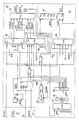
- an input video signal IN from a video source is input to a buffer amplifier 10.
- the output of the buffer amplifier 10 is input to a phase locked loop (PLL) 12 and to a subcarrier/horizontal sync (SC/H) logic circuit 14.
- the PLL 12 generates an output clock BCK which is synchronized to the color subcarrier of the input signal IN. Variations in the color subcarrier frequency appear at node A as a control voltage which is used to correct the oscillator frequency of the PLL 12.
- the variations at node A are also input to a comparator 16 to which a reference voltage REF, representative of the nominal voltage at node A, is input.
- the output of the comparator 16 is a time base error signal.
- the time base error signal is input to a time base corrector (TBC) mode selector 18.
- TBC time base corrector
- the three TBC modes from the TBC mode selector 18 are: (i) STABLE -- indicating that the video input signal is from a direct video feed such as a video camera; (ii) DIRECT -- indicating that the video input signal is from a video tape recorder (VTR) on which input video was recorded directly; and (iii) NON-DIRECT -- indicating that the video input signal is from a VTR on which input video was recorded in a heterodyned format such as color-under.
- the SC/H logic circuit 14 generates a sync window using the clock BCK, the sync window being generated about the nominal position of the horizontal sync from the composite sync /CS of the input signal.
- the phase relationship between the composite sync and the color subcarrier is essentially constant so that the horizontal sync pulse occurs within the sync window and no errors are detected.
- the phase relationship between the composite sync and the color subcarrier varies. If the variation in phase causes the horizontal sync pulse to fall outside the sync window, then an error signal /SERR is generated from the SC/H logic circuit 14 together with an indication SAHORIZ of whether the horizontal sync pulse occurs before or after the sync window.
- An up/down counter 20 counts the errors /SERR according to the status of SAHORIZ to provide an average sync error.
- the errors /SERR also are counted in an error counter 22. If the number of errors for a given portion of a video field, the given portion being determined by a vertical window defining a given number of horizontal lines, exceed a predetermined amount for a predetermined number of consecutive fields, then a non-direct color indicator /NDC is output to the TBC mode selector 18.
- the clock BCK from the PLL 12 is input to a first counter 24 which counts the clock pulses of BCK until reset by a signal /SAR from the up/down counter 20 at the end of each horizontal line of video data.
- the output of the first counter 24 is input as an address to a programmable read only memory (PROM) 26.
- PROM programmable read only memory
- a data word at the output from the PROM 26 corresponding to the address from the first counter 24 is clocked into a latch 28.
- the data word from the PROM 26 provides a data line SAHWP which is low for all addresses except where the window is desired at the start of the next horizontal line of video data.
- the length of the output from the latch for SAHWP is a function of the period of BCK.
- the window signal SAHWP is input to a delay line 30 to lengthen the window pulse.
- the horizontal window pulse signal HW from the delay line 30 is input to a first flip-flop 32 configured as a D-type.
- the bit value of the HW signal at the D input of the first flip-flop 32 is transferred to the output Q at the leading edge of the horizontal sync pulse of the composite sync /CS signal applied to the clock input.
- the output of the first flip-flop 32 is input to a second flip-flop 34 configured as a D-type.
- the second flip-flop 34 is clocked by BCK and produces at the output Q the error signal /SERR.
- /SERR is applied to the set terminal S of the first flip-flop 32 to cause the output of the first flip-flop to go high, which in turn on the next BCK clock pulse terminates the error signal, i.e., provides a definite pulse for /SERR.
- the HW signal is high when the leading edge of horizontal sync from /CS occurs, the output of the first flip-flop 32 is high and on the next pulse of BCK the output of the second flip-flop is high, indicating that the sync pulse occurred within the horizontal window.
- the output of the first flip-flop 32 goes low and on the next BCK pulse the output of the second flip-flop 34 goes low, indicating that the sync pulse is outside the horizontal window.
- the first flip-flop 32 is set and the resulting high output from the first flip-flop causes the output of the second flip-flop to return high on the next BCK pulse.
- /SERR also is input to three counters 36, 38, 40 which are clocked by BCK. The first two counters 36, 38 form an up/down counter which increments for each /SERR pulse from the second flip-flop 34.
- a signal SAHORIZ from the latch 28 as output by the PROM 26 indicates whether the /SERR pulse results in an increment or a decrement. If SAHORIZ is high when the horizontal sync pulse from /CS occurs, then /SERR increments the up/down counter. If SAHORIZ is low when the horizontal sync pulse from /CS occurs, then /SERR decrements the up/down counter.
- the output of the up/down counters 36, 38 is input to a programmed array logic (PAL) circuit 42.
- the output of the PAL 42 provides an indication of the direction of the average phase error (/RIGHT, /LEFT) of the input signal and a reset signal /SAR to the first counter 24 to begin counting for the next horizontal line.
- the counter 40 counts each /SERR pulse for each horizontal line defined by a vertical window VWAVG, regardless of whether the horizontal sync pulse occurs before or after the horizontal window HW.
- the counter 40 outputs a preliminary non-direct color signal /PNDC when the count reaches a predetermined value before the counter is reset by a reset signal /CLSAC which occurs each video field.
- /PNDC is input to an error state machine 44, such as a PAL, which acts as a digital filter.
- a PAL which acts as a digital filter.
- the clear signal /CLSAC is received
- the state changes from 11 to 01 and then after a given time duration changes to the 10 state which produces a /LD pulse of the given time duration.
- the error state machine 44 remains in the 10 state so long as no read signal (/VLTAVG) is received.
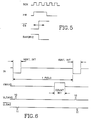
- the read signal VLTAVG the state transitions from 10 to 11 to begin the cycle again. As shown in Fig. 6 the read signal and clear signal occur once each field of video data during the vertical sync interval, with the read signal occurring first and the clear signal occurring one horizontal line later.
- the second state diagram of Fig. 4 is a function of the /LD pulse from the first diagram and the /PNDC signal from the counter 40.
- the Q4 output of the error state machine 44 provides the /NDC signal which indicates the presence as a video input signal of a heterodyned color signal source.
- the unused states ending in 1 automatically are changed to the 1111 state, and the unused states ending in 0 are automatically changed to the 1110 state. For all other states the state remains unchanged so long as the /LD pulse from the first state diagram is not present.
- /LD occurs once per video field, then the output of the counter 40 is checked to determine whether the preliminary non-direct color signal /PNDC is present.
- /PNDC is present for three consecutive fields in conjunction with /LD
- the states transition from 1111 to 1110 to 1100 to 0110 and the state machine 44 remains in the 0110 state so long as /PNDC is present for each subsequent /LD pulse.
- phase errors may occur only in alternate fields.
- /PNDC occurs every other field so that the states transition from 1111 to 1110 to 1011 to 1100 to 1101 to 0110.
- Subsequent fields cause the states to transition back and forth between 0111 and 0110. If during the state transitions from 1111 to 0110 there are two or three consecutive fields without /PNDC, the states transition back to 1111 from 1110 via 1011 or from 1100 via 1101 and 1011.
- /NDC is provided at the output from state 0110 and is held until the error state machine returns to state 1111.
- To return to state 1111 from 0110 four consecutive fields without /PNDC are required to transition through states 0111, 0101 and 0011. If during the transition from 0110 to 1111 a /PNDC occurs in one of the fields, the state transitions back to 0110 directly from 0111, 0101 and 0011. /NDC is removed when the state is returned to 1111.
- the present invention provides a heterodyne color signal recognition circuit by adding all the SC/H phase errors of a video input signal that occur within a predetermined portion of a video field of the input signal, outputting a preliminary non-direct color signal for each field indicating the presence of at least a predetermined number of errors within the field, and digitally filtering the preliminary non-direct color signal to assure at least three consecutive odd and/or even fields having errors to output a non-direct color signal to a time base correction mode selector.
Landscapes
- Engineering & Computer Science (AREA)
- Multimedia (AREA)
- Signal Processing (AREA)
- Processing Of Color Television Signals (AREA)
- Television Signal Processing For Recording (AREA)
Applications Claiming Priority (2)
| Application Number | Priority Date | Filing Date | Title |
|---|---|---|---|
| US07/093,287 US4777522A (en) | 1987-09-04 | 1987-09-04 | Nonstandard video signal detector having h-sync to subcarrier phase detection |
| US93287 | 1987-09-04 |
Publications (2)
| Publication Number | Publication Date |
|---|---|
| EP0306005A2 true EP0306005A2 (de) | 1989-03-08 |
| EP0306005A3 EP0306005A3 (de) | 1991-10-30 |
Family
ID=22238124
Family Applications (1)
| Application Number | Title | Priority Date | Filing Date |
|---|---|---|---|
| EP19880114216 Withdrawn EP0306005A3 (de) | 1987-09-04 | 1988-08-31 | Heterodynfarbbildsignalerkennung |
Country Status (3)
| Country | Link |
|---|---|
| US (1) | US4777522A (de) |
| EP (1) | EP0306005A3 (de) |
| JP (1) | JPH0722418B2 (de) |
Families Citing this family (2)
| Publication number | Priority date | Publication date | Assignee | Title |
|---|---|---|---|---|
| JP2523886B2 (ja) * | 1989-08-04 | 1996-08-14 | 松下電器産業株式会社 | ドット妨害除去装置及び色副搬送波垂直相関検出装置 |
| US5166781A (en) * | 1991-05-10 | 1992-11-24 | Thomson Consumer Electronics, Inc. | Apparatus for identifying standard and non-standard video signals |
Family Cites Families (5)
| Publication number | Priority date | Publication date | Assignee | Title |
|---|---|---|---|---|
| US4335403A (en) * | 1981-01-09 | 1982-06-15 | Zenith Radio Corporation | Horizontal countdown system for television receivers |
| EP0059773B1 (de) * | 1981-03-09 | 1984-02-01 | Deutsche ITT Industries GmbH | Digitalschaltung zur Abgabe eines Binärsignals beim Auftreten eines fest vorgegebenen Frequenzverhältnisses zweier Signale und deren Verwendung in Farbfernsehempfängern |
| DE3171427D1 (en) * | 1981-11-19 | 1985-08-22 | Itt Ind Gmbh Deutsche | Digital circuit delivering a binary signal whenever the frequency ration of the line/and the field frequency occurs |
| US4503455A (en) * | 1982-02-09 | 1985-03-05 | Nippon Electric Co., Ltd. | Control signal generator for a television signal codec |
| US4635099A (en) * | 1985-02-04 | 1987-01-06 | Rca Corporation | Apparatus for detecting nonstandard video signals |
-
1987
- 1987-09-04 US US07/093,287 patent/US4777522A/en not_active Expired - Lifetime
-
1988
- 1988-08-31 EP EP19880114216 patent/EP0306005A3/de not_active Withdrawn
- 1988-09-01 JP JP63219615A patent/JPH0722418B2/ja not_active Expired - Lifetime
Also Published As
| Publication number | Publication date |
|---|---|
| EP0306005A3 (de) | 1991-10-30 |
| JPS6482883A (en) | 1989-03-28 |
| US4777522A (en) | 1988-10-11 |
| JPH0722418B2 (ja) | 1995-03-08 |
Similar Documents
| Publication | Publication Date | Title |
|---|---|---|
| US4175267A (en) | Method and apparatus of inserting an address signal in a video signal | |
| US5253061A (en) | Method and apparatus for controlling television image processing based upon television program detection | |
| US5956090A (en) | Television standards converter with time-code conversion function | |
| US4203076A (en) | Clock pulse signal generator having an automatic frequency control circuit | |
| US4729024A (en) | Synchronizing pulse signal generation device | |
| US4520394A (en) | Horizontal scanning frequency multiplying circuit | |
| US4974081A (en) | Clock pulse generating circuit | |
| US4516164A (en) | Apparatus for decoding video address code signals | |
| US4376291A (en) | Method of compensating time faults in a digital color television signal | |
| EP0418901B1 (de) | Synchronisierungssignalgenerator für ein Bildsignalwiedergabegerät | |
| US4777522A (en) | Nonstandard video signal detector having h-sync to subcarrier phase detection | |
| US3878557A (en) | Color framing videotape recording apparatus and method | |
| JP4541452B2 (ja) | 遅延補正回路 | |
| US4349832A (en) | Digital data rate corrector and time base corrector | |
| US4300171A (en) | Magnetic recording medium direction sensing | |
| US5012332A (en) | Correcting data reading device in a digital convergence correcting device | |
| EP0349990A2 (de) | Videoplattenspieler mit einer Klemmschaltung für MUSE-Signale | |
| EP0104817B1 (de) | Automatisches Chrominanzsignalfilter | |
| US5303046A (en) | Video signal processing apparatus with time base correction and inhibition of horizontal sync signal replacement during vertical flyback | |
| CA1245348A (en) | Time base corrector | |
| EP0176257A2 (de) | Magnetisches Aufzeichnungsgerät für die intermittierende Aufnahme eines Videosignales | |
| KR930007378Y1 (ko) | 비디오 테이프의 화질보상회로 | |
| US4291335A (en) | Vertical synchronizing signal detector | |
| US5099312A (en) | Timebase corrector | |
| JP3254726B2 (ja) | 同期信号検出回路 |
Legal Events
| Date | Code | Title | Description |
|---|---|---|---|
| PUAI | Public reference made under article 153(3) epc to a published international application that has entered the european phase |
Free format text: ORIGINAL CODE: 0009012 |
|
| AK | Designated contracting states |
Kind code of ref document: A2 Designated state(s): DE FR GB |
|
| PUAL | Search report despatched |
Free format text: ORIGINAL CODE: 0009013 |
|
| AK | Designated contracting states |
Kind code of ref document: A3 Designated state(s): DE FR GB |
|
| 17P | Request for examination filed |
Effective date: 19920206 |
|
| STAA | Information on the status of an ep patent application or granted ep patent |
Free format text: STATUS: THE APPLICATION IS DEEMED TO BE WITHDRAWN |
|
| 18D | Application deemed to be withdrawn |
Effective date: 19920505 |