EP0306049A2 - Dispositif pour brûler les particules dans les pots d'échappement des moteurs diesel - Google Patents
Dispositif pour brûler les particules dans les pots d'échappement des moteurs diesel Download PDFInfo
- Publication number
- EP0306049A2 EP0306049A2 EP88114384A EP88114384A EP0306049A2 EP 0306049 A2 EP0306049 A2 EP 0306049A2 EP 88114384 A EP88114384 A EP 88114384A EP 88114384 A EP88114384 A EP 88114384A EP 0306049 A2 EP0306049 A2 EP 0306049A2
- Authority
- EP
- European Patent Office
- Prior art keywords
- wire mesh
- particles
- hollow cylinder
- flow channel
- flow
- Prior art date
- Legal status (The legal status is an assumption and is not a legal conclusion. Google has not performed a legal analysis and makes no representation as to the accuracy of the status listed.)
- Withdrawn
Links
Images

Classifications
-
- F—MECHANICAL ENGINEERING; LIGHTING; HEATING; WEAPONS; BLASTING
- F01—MACHINES OR ENGINES IN GENERAL; ENGINE PLANTS IN GENERAL; STEAM ENGINES
- F01N—GAS-FLOW SILENCERS OR EXHAUST APPARATUS FOR MACHINES OR ENGINES IN GENERAL; GAS-FLOW SILENCERS OR EXHAUST APPARATUS FOR INTERNAL-COMBUSTION ENGINES
- F01N3/00—Exhaust or silencing apparatus having means for purifying, rendering innocuous, or otherwise treating exhaust
- F01N3/02—Exhaust or silencing apparatus having means for purifying, rendering innocuous, or otherwise treating exhaust for cooling, or for removing solid constituents of, exhaust
- F01N3/021—Exhaust or silencing apparatus having means for purifying, rendering innocuous, or otherwise treating exhaust for cooling, or for removing solid constituents of, exhaust by means of filters
- F01N3/033—Exhaust or silencing apparatus having means for purifying, rendering innocuous, or otherwise treating exhaust for cooling, or for removing solid constituents of, exhaust by means of filters in combination with other devices
- F01N3/035—Exhaust or silencing apparatus having means for purifying, rendering innocuous, or otherwise treating exhaust for cooling, or for removing solid constituents of, exhaust by means of filters in combination with other devices with catalytic reactors
-
- F—MECHANICAL ENGINEERING; LIGHTING; HEATING; WEAPONS; BLASTING
- F01—MACHINES OR ENGINES IN GENERAL; ENGINE PLANTS IN GENERAL; STEAM ENGINES
- F01N—GAS-FLOW SILENCERS OR EXHAUST APPARATUS FOR MACHINES OR ENGINES IN GENERAL; GAS-FLOW SILENCERS OR EXHAUST APPARATUS FOR INTERNAL-COMBUSTION ENGINES
- F01N13/00—Exhaust or silencing apparatus characterised by constructional features
- F01N13/009—Exhaust or silencing apparatus characterised by constructional features having two or more separate purifying devices arranged in series
-
- F—MECHANICAL ENGINEERING; LIGHTING; HEATING; WEAPONS; BLASTING
- F01—MACHINES OR ENGINES IN GENERAL; ENGINE PLANTS IN GENERAL; STEAM ENGINES
- F01N—GAS-FLOW SILENCERS OR EXHAUST APPARATUS FOR MACHINES OR ENGINES IN GENERAL; GAS-FLOW SILENCERS OR EXHAUST APPARATUS FOR INTERNAL-COMBUSTION ENGINES
- F01N3/00—Exhaust or silencing apparatus having means for purifying, rendering innocuous, or otherwise treating exhaust
- F01N3/02—Exhaust or silencing apparatus having means for purifying, rendering innocuous, or otherwise treating exhaust for cooling, or for removing solid constituents of, exhaust
- F01N3/021—Exhaust or silencing apparatus having means for purifying, rendering innocuous, or otherwise treating exhaust for cooling, or for removing solid constituents of, exhaust by means of filters
- F01N3/0217—Exhaust or silencing apparatus having means for purifying, rendering innocuous, or otherwise treating exhaust for cooling, or for removing solid constituents of, exhaust by means of filters the filtering elements having the form of hollow cylindrical bodies
-
- F—MECHANICAL ENGINEERING; LIGHTING; HEATING; WEAPONS; BLASTING
- F01—MACHINES OR ENGINES IN GENERAL; ENGINE PLANTS IN GENERAL; STEAM ENGINES
- F01N—GAS-FLOW SILENCERS OR EXHAUST APPARATUS FOR MACHINES OR ENGINES IN GENERAL; GAS-FLOW SILENCERS OR EXHAUST APPARATUS FOR INTERNAL-COMBUSTION ENGINES
- F01N3/00—Exhaust or silencing apparatus having means for purifying, rendering innocuous, or otherwise treating exhaust
- F01N3/02—Exhaust or silencing apparatus having means for purifying, rendering innocuous, or otherwise treating exhaust for cooling, or for removing solid constituents of, exhaust
- F01N3/021—Exhaust or silencing apparatus having means for purifying, rendering innocuous, or otherwise treating exhaust for cooling, or for removing solid constituents of, exhaust by means of filters
- F01N3/023—Exhaust or silencing apparatus having means for purifying, rendering innocuous, or otherwise treating exhaust for cooling, or for removing solid constituents of, exhaust by means of filters using means for regenerating the filters, e.g. by burning trapped particles
-
- F—MECHANICAL ENGINEERING; LIGHTING; HEATING; WEAPONS; BLASTING
- F01—MACHINES OR ENGINES IN GENERAL; ENGINE PLANTS IN GENERAL; STEAM ENGINES
- F01N—GAS-FLOW SILENCERS OR EXHAUST APPARATUS FOR MACHINES OR ENGINES IN GENERAL; GAS-FLOW SILENCERS OR EXHAUST APPARATUS FOR INTERNAL-COMBUSTION ENGINES
- F01N3/00—Exhaust or silencing apparatus having means for purifying, rendering innocuous, or otherwise treating exhaust
- F01N3/08—Exhaust or silencing apparatus having means for purifying, rendering innocuous, or otherwise treating exhaust for rendering innocuous
- F01N3/10—Exhaust or silencing apparatus having means for purifying, rendering innocuous, or otherwise treating exhaust for rendering innocuous by thermal or catalytic conversion of noxious components of exhaust
- F01N3/24—Exhaust or silencing apparatus having means for purifying, rendering innocuous, or otherwise treating exhaust for rendering innocuous by thermal or catalytic conversion of noxious components of exhaust characterised by constructional aspects of converting apparatus
- F01N3/28—Construction of catalytic reactors
- F01N3/2882—Catalytic reactors combined or associated with other devices, e.g. exhaust silencers or other exhaust purification devices
-
- F—MECHANICAL ENGINEERING; LIGHTING; HEATING; WEAPONS; BLASTING
- F01—MACHINES OR ENGINES IN GENERAL; ENGINE PLANTS IN GENERAL; STEAM ENGINES
- F01N—GAS-FLOW SILENCERS OR EXHAUST APPARATUS FOR MACHINES OR ENGINES IN GENERAL; GAS-FLOW SILENCERS OR EXHAUST APPARATUS FOR INTERNAL-COMBUSTION ENGINES
- F01N2250/00—Combinations of different methods of purification
- F01N2250/02—Combinations of different methods of purification filtering and catalytic conversion
-
- F—MECHANICAL ENGINEERING; LIGHTING; HEATING; WEAPONS; BLASTING
- F02—COMBUSTION ENGINES; HOT-GAS OR COMBUSTION-PRODUCT ENGINE PLANTS
- F02B—INTERNAL-COMBUSTION PISTON ENGINES; COMBUSTION ENGINES IN GENERAL
- F02B3/00—Engines characterised by air compression and subsequent fuel addition
- F02B3/06—Engines characterised by air compression and subsequent fuel addition with compression ignition
Definitions
- the invention relates to a device for soot particle combustion in the exhaust system of a diesel engine.
- the exhaust gases from diesel engines contain, in addition to the gaseous pollutants, such as carbon monoxide, hydrocarbon compounds and nitrogen oxides, also organic and inorganic particles. These particles consist essentially of carbon, condensable and carbon-bonded hydrocarbon compounds, sulfur compounds and other particles. For reasons of environmental protection, attempts are made to retain the highest possible proportion of these particles contained in the exhaust gas stream. For this purpose, filter systems are used, in which the particles are to accumulate up to a certain degree of loading and which are then separated by a so-called. Filter regeneration be brought back into a condition necessary for the correct operation of the engine.
- the gaseous pollutants such as carbon monoxide, hydrocarbon compounds and nitrogen oxides
- organic and inorganic particles consist essentially of carbon, condensable and carbon-bonded hydrocarbon compounds, sulfur compounds and other particles.
- filter systems are used, in which the particles are to accumulate up to a certain degree of loading and which are then separated by a so-called. Filter regeneration be brought back into a condition necessary for the correct operation of the engine.
- This regeneration must be carried out at the latest when the permissible exhaust gas back pressure is reached.
- several methods are known in which the oxidizable particle load is burned. If the exhaust gases are at a sufficiently high temperature when they exit the engine, this can be done by self-ignition. Another measure is to carry out additional external heating or spark ignition. Particle combustion can also be achieved by lowering the autoignition temperature by catalysis or by adding Oxidation promoting agents take place. This measure is carried out in view of the fact that the ignition temperature of the soot itself is relatively high. Under favorable conditions, however, the catalytic coating already leads to burning at temperatures below this range, so that an external ignition aid can be dispensed with.
- the temperature of the exhaust gases is still below the ignition temperature.
- the invention has for its object to provide a device for soot particle combustion of the type mentioned, with which the temperature of the particles is increased in a simple manner.
- a basic idea of the invention is to be seen in the fact that the kinetic energy of the particles emerging from the engine at high speed is converted into thermal energy by friction, which leads to an increase in the particle temperature. Depending on the flow rate, it is possible to increase the particle temperature up to 80 ° C.
- the invention has the advantage that soot particles are burned by self-ignition even if the exhaust gas temperature is below the ignition point when exiting the engine.
- Another advantage can be seen in the fact that soot particles accumulate in the wire knit in the starting phase meln, and that these are subsequently burned when the wire mesh is heated sufficiently by the frictional heat.
- Another advantage is that a front silencer can be omitted. An additional fuel consumption or a loss of performance is avoided.
- the radial guide device consists of a spiral housing.
- the radial guide device can also be expedient for the radial guide device to consist of guide vanes which are oriented tangentially or radially.
- the guide device consists of a thick-walled hollow cylinder made of catalytically coated material with a plurality of through openings, that this hollow cylinder is wrapped with the wire mesh, and that an annular space is present around the wire mesh for the circulation of the particles.
- this hollow cylinder can also be formed from a foam ceramic.
- the wire mesh may be surrounded with a perforated sheet metal jacket. In this way it is prevented that the particles emerging from the motor at high speed remove wire mesh or porous material.
- the wire mesh can also be advantageous to coat the wire mesh with catalytic material.
- the highly porous hollow cylinder can be downsized or saved.
- the radial guide device it is possible to arrange the wire mesh in the form of a hollow cylinder between the cylindrical outlet space and an outer annular space and to produce the inner and outer cylinder jacket from perforated sheet metal.
- the combustion is further promoted in that the flow channel is provided with an oxygen supply.
- the feed preferably comprises a heat exchanger on the motor housing and / or on the exhaust system.
- the guide device consists of radially, tangentially or spirally oriented guide surfaces
- a paddle wheel driven by the exhaust gases is arranged in the cylindrical outlet space. The deflection and outflow of the exhaust gas in the axial direction is facilitated by this measure.
- auxiliary energy can be tapped from the shaft of the paddle wheel.
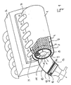
- FIG. 1 illustrates a cylindrical housing 1 made of rustproof stainless steel in the immediate vicinity of an engine block 2 of a diesel engine, to which it is connected via an exhaust gas outlet 3.
- the exhaust gases are introduced tangentially into an annular flow channel 4, in which they flow according to arrows 5 around a layered hollow cylinder 6. In this way, the particles contained in the exhaust gas come into contact over a large area with the outer surface of the hollow cylinder 6 and its layers.
- the hollow cylinder 6 consists of a perforated sheet jacket 7, a winding of wire mesh 8 and a catalytically coated material 9 provided with interconnecting pores.
- the hollow cylinder 6 encloses a cylindrical outlet space 10 with an axial outlet 11, which is connected to an outlet tube 12 connected is.
- the perforated sheet jacket 7 is preferably made of stainless steel. In this construction, the exhaust gases and the particles contained therein are guided radially from the outside through the hollow cylinder 6 and then exit axially into the outlet pipe 12.
- the particles on the perforated sheet jacket 7 and in particular on the wire mesh 8 generate frictional heat, which leads to heating of the particles, the perforated sheet jacket 7 and the wire mesh 8.
- the wire mesh With sufficient cynetic energy, the wire mesh is made to glow. This temperature increase and the catalytic addition lead to the auto-ignition temperature of the soot particles being reached.
- the soot particles When passing through the hollow cylinder 6, the soot particles are burned.
- the wire mesh 8 has the function of a heat store. At the same time, it also serves as an elastic mounting for the catalytic material 9, which is mechanically relatively sensitive when it is designed as a porous foam ceramic.
- the wire mesh 8 can be wrapped around the catalytic material 9 in a single layer or in several layers. In principle, it is also possible to use 8 steel wool instead of the wire mesh.
- the wire mesh 8 can also be coated with catalytic material.
- an insert of further wire mesh 13 is arranged in the outlet pipe 12 transversely to the direction of flow and is surrounded in a cage made of rust-free mesh sieves 14 or perforated sheet metal.
- a further insert arranged transversely to the direction of flow, made of highly porous catalytic material 16 or of a catalytically coated honeycomb body.
- the further wire mesh 13, which can be coated with catalytic material, serves like the wire mesh 8 as a heat accumulator and incandescent body, which promote the soot particle combustion.
- the flow channel 4 runs in a spiral, the housing 1 being designed as a spiral housing.
- a loose layer of wire mesh 8, which is coated with catalytic material, is inserted into the spiral.
- the combustion of the soot particles in the exhaust gas of the diesel engine is in turn promoted by the fact that due to the particle friction on the wire mesh 8, frictional heat is generated which brings the soot particles into the self-ignition temperature range.
- This area is reduced by adding the catalytic material.
- the surface of the housing 1 can also be roughened.
- a shaft 17 is arranged coaxially to the housing 1 in the outlet space 10. It carries a paddle wheel 18 which is driven by the exhaust gas emerging from the volute casing. The pitch of the impeller 18 is selected so that the exhaust gases are blown out of the outlet space 10 into the outlet pipe 12.
- a drive disk 20 is attached to a shaft end 19 in a rotationally fixed manner and can serve as an auxiliary drive.
- FIG 3 shows a view of the paddle wheel 18 in the axial direction.
- FIG. 2 further illustrates an oxygen supply into the outlet connection 3, with which the exhaust gas is enriched with oxygen before it enters the housing 1 to support the combustion process.
- the oxygen supply comprises a distributor 25 and a first and second feed line 21, 22.
- the first feed line 21 leads from a first heat exchanger 23 directly on the engine block 2 to a second heat exchanger 24, which is arranged in the form of a spiral downstream after the insert 16 in the outlet pipe 12 is. From there, the preheated oxygen is fed into the distributor 25 via the second feed line 22.
- the temperature of the supplied oxygen is thus increased on the one hand by the engine heat and on the other hand by the exhaust gas heat.
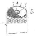
- Figure 4 shows an alternative embodiment of the hollow cylinder 6 ', as shown in Fig. 1. It consists of an outer perforated sheet jacket 7 and a perforated sheet inner jacket 26, both preferably made of stainless steel. In between is wire mesh 8, which can be wound in several layers. The wire mesh 8 is coated with catalytic material to lower the self-ignition temperature of the soot particles.
- This hollow cylinder 6 also has the function of a guide device which directs the particles circulating around the hollow cylinder 6 at high speed radially from the outside inwards into the outlet space 10, which is delimited by the perforated sheet metal inner jacket 26.
Landscapes
- Engineering & Computer Science (AREA)
- Chemical & Material Sciences (AREA)
- Combustion & Propulsion (AREA)
- Mechanical Engineering (AREA)
- General Engineering & Computer Science (AREA)
- Chemical Kinetics & Catalysis (AREA)
- Health & Medical Sciences (AREA)
- Toxicology (AREA)
- Processes For Solid Components From Exhaust (AREA)
- Exhaust Gas After Treatment (AREA)
Applications Claiming Priority (2)
| Application Number | Priority Date | Filing Date | Title |
|---|---|---|---|
| DE3729367 | 1987-09-02 | ||
| DE19873729367 DE3729367A1 (de) | 1987-09-02 | 1987-09-02 | Vorrichtung zur partikel-verbrennung in der abgasanlage eines dieselmotors |
Publications (2)
| Publication Number | Publication Date |
|---|---|
| EP0306049A2 true EP0306049A2 (fr) | 1989-03-08 |
| EP0306049A3 EP0306049A3 (fr) | 1990-04-25 |
Family
ID=6335085
Family Applications (1)
| Application Number | Title | Priority Date | Filing Date |
|---|---|---|---|
| EP88114384A Withdrawn EP0306049A3 (fr) | 1987-09-02 | 1988-09-02 | Dispositif pour brûler les particules dans les pots d'échappement des moteurs diesel |
Country Status (2)
| Country | Link |
|---|---|
| EP (1) | EP0306049A3 (fr) |
| DE (1) | DE3729367A1 (fr) |
Families Citing this family (1)
| Publication number | Priority date | Publication date | Assignee | Title |
|---|---|---|---|---|
| DE4109847C2 (de) * | 1991-03-26 | 1993-12-09 | Daimler Benz Ag | Anordnung eines Rußfilters an einem Dieselmotor |
Family Cites Families (12)
| Publication number | Priority date | Publication date | Assignee | Title |
|---|---|---|---|---|
| DE1194640B (de) * | 1960-05-11 | 1965-06-10 | Atomkraftwerk Rheinsberg Mit B | Abscheider mit rotierenden Teilen zum Abscheiden von Schwebstoffen aus gasfoermigen Medien, insbesondere zum Reinigen von Kraftfahrzeugabgasen |
| US3485593A (en) * | 1967-06-09 | 1969-12-23 | Ethyl Corp | Exhaust treating device |
| US4104360A (en) * | 1973-02-05 | 1978-08-01 | Standard Oil Company | Process for reducing oxides nitrogen in the exhaust gas from internal combustion engines |
| GB1462993A (en) * | 1973-04-11 | 1977-01-26 | Bayerische Motoren Werke Ag | Exhaust gas filter |
| US3927525A (en) * | 1973-05-25 | 1975-12-23 | Gen Motors Corp | Engine with exhaust manifold converter-reactor |
| DE2428965A1 (de) * | 1974-06-15 | 1976-01-02 | Bosch Gmbh Robert | Abgasreaktor |
| DE2750960A1 (de) * | 1977-11-15 | 1979-05-17 | Daimler Benz Ag | Russfilter im abgasstrom von luftverdichtenden brennkraftmaschinen |
| DE3027499A1 (de) * | 1980-07-19 | 1982-02-18 | Knecht Filterwerke Gmbh, 7000 Stuttgart | Abgasfilter fuer verbrennungsmotoren |
| DE3228325A1 (de) * | 1982-07-29 | 1984-02-02 | Fa. J. Eberspächer, 7300 Esslingen | Filter- und nachverbrennungseinrichtung fuer abgase |
| DE3537976C1 (en) * | 1985-10-25 | 1987-04-23 | Didier Werke Ag | Filter device for soot particle filtration |
| DE3538105A1 (de) * | 1985-10-26 | 1987-04-30 | Man Technologie Gmbh | Filter fuer den abgasstrom einer brennkraftmaschine |
| DE8620832U1 (de) * | 1986-08-02 | 1986-09-18 | Drache Keramikfilter Produktions-GmbH, 6252 Diez | Staub- oder Rußfilter |
-
1987
- 1987-09-02 DE DE19873729367 patent/DE3729367A1/de not_active Ceased
-
1988
- 1988-09-02 EP EP88114384A patent/EP0306049A3/fr not_active Withdrawn
Also Published As
| Publication number | Publication date |
|---|---|
| EP0306049A3 (fr) | 1990-04-25 |
| DE3729367A1 (de) | 1989-03-16 |
Similar Documents
| Publication | Publication Date | Title |
|---|---|---|
| EP1440226B1 (fr) | Filtre particulaire ouvert muni d'un element chauffant | |
| DE60016218T2 (de) | Vorrichtung und verfahren zum entfernen von russpartikeln aus abgasen von verbrennungsprozessen | |
| EP0504719B1 (fr) | Filtre pour gaz d'échappement et/ou convertisseur catalytique | |
| EP1866591B1 (fr) | Echangeur thermique pour gaz d'echappement, notamment refroidisseur de gaz d'echappement pour le recyclage des gaz d'echappement dans les vehicules a moteur | |
| DE102014110592B4 (de) | Nachbehandlungskomponente | |
| EP0148358A2 (fr) | Catalyseur pour la combustion et la conversion de gaz et des hydrocarbures supérieurs, ainsi que dispositif pour la réduction d'oxydes d'azote et brûleur de gaz d'échappement muni d'un tel catalyseur | |
| EP1479883A1 (fr) | Procédé et dispositif de purification des gaz d'échappement | |
| DE102006049005B4 (de) | Fluidmitnahmevorrichtung sowie damit ausgestattetes Abgassystem | |
| DE102015105559A1 (de) | Integriertes mischsystem für ein abgasnachbehandlungssystem | |
| WO2005001252A1 (fr) | Systeme de retraitement des gaz d'echappement pourvu d'une enveloppe a retour et procede de retraitement des gaz d'echappement correspondant | |
| EP3348905B1 (fr) | Ensemble chambre de combustion | |
| DE102014105836A1 (de) | Verbrennungsmotor und Abgasnachbehandlungssystem | |
| WO2020260331A1 (fr) | Dispositif de post-traitement de gaz d'échappement | |
| EP0233860A2 (fr) | Dispositif d'épuration de gaz d'échappement | |
| DE19855092B4 (de) | Vorrichtung und Verfahren zum Reinigen des Abgases einer Brennkraftmaschine | |
| DE102004018393A1 (de) | Abgasnachbehandlungseinrichtung | |
| DE4210358C2 (de) | Vorrichtung zur Vergrößerung von kleinen klebrigen Partikeln | |
| EP4155513B1 (fr) | Boîtier de guidage des gaz d'échappement | |
| DE102020129001A1 (de) | Abgasanlage mit Abgasturbolader, Ejektor und Abgaskatalysator | |
| DE3729367A1 (de) | Vorrichtung zur partikel-verbrennung in der abgasanlage eines dieselmotors | |
| WO2002102493A2 (fr) | Filtre a particules fonctionnant sur la base de la combustion de suie pour moteurs diesel | |
| DE10300408A1 (de) | Verfahren zur Behandlung eines Fluids und Wabenkörper | |
| EP1101019A1 (fr) | Procede et dispositif de retraitement des gaz d'echappement d'un moteur a combustion interne | |
| DE2248442A1 (de) | Katalysator zur katalytischen reinigung von abgasen | |
| DE2341265A1 (de) | Einrichtung zur katalytischen abgasreinigung |
Legal Events
| Date | Code | Title | Description |
|---|---|---|---|
| PUAI | Public reference made under article 153(3) epc to a published international application that has entered the european phase |
Free format text: ORIGINAL CODE: 0009012 |
|
| AK | Designated contracting states |
Kind code of ref document: A2 Designated state(s): AT BE CH DE ES FR GB GR IT LI LU NL SE |
|
| PUAL | Search report despatched |
Free format text: ORIGINAL CODE: 0009013 |
|
| AK | Designated contracting states |
Kind code of ref document: A3 Designated state(s): AT BE CH DE ES FR GB GR IT LI LU NL SE |
|
| 17P | Request for examination filed |
Effective date: 19900517 |
|
| 17Q | First examination report despatched |
Effective date: 19900905 |
|
| STAA | Information on the status of an ep patent application or granted ep patent |
Free format text: STATUS: THE APPLICATION IS DEEMED TO BE WITHDRAWN |
|
| 18D | Application deemed to be withdrawn |
Effective date: 19910116 |