EP0306061A2 - Moteur externe pour canon automatique - Google Patents
Moteur externe pour canon automatique Download PDFInfo
- Publication number
- EP0306061A2 EP0306061A2 EP88115214A EP88115214A EP0306061A2 EP 0306061 A2 EP0306061 A2 EP 0306061A2 EP 88115214 A EP88115214 A EP 88115214A EP 88115214 A EP88115214 A EP 88115214A EP 0306061 A2 EP0306061 A2 EP 0306061A2
- Authority
- EP
- European Patent Office
- Prior art keywords
- rocking lever
- follower
- gear
- journaled
- cams
- Prior art date
- Legal status (The legal status is an assumption and is not a legal conclusion. Google has not performed a legal analysis and makes no representation as to the accuracy of the status listed.)
- Withdrawn
Links
Images


Classifications
-
- F—MECHANICAL ENGINEERING; LIGHTING; HEATING; WEAPONS; BLASTING
- F41—WEAPONS
- F41A—FUNCTIONAL FEATURES OR DETAILS COMMON TO BOTH SMALLARMS AND ORDNANCE, e.g. CANNONS; MOUNTINGS FOR SMALLARMS OR ORDNANCE
- F41A7/00—Auxiliary mechanisms for bringing the breech-block or bolt or the barrel to the starting position before automatic firing; Drives for externally-powered guns; Remote-controlled gun chargers
- F41A7/08—Drives for externally-powered guns, i.e. drives for moving the breech-block or bolt by an external force during automatic firing
Definitions
- This invention relates to an external drive particularly suitable for a machine gun having two gun barrels and a linkage which alternatively drives each breech bolt via a cam operated accelerator.
- a two barreled machine gun having an operating mechanism driven by an external source is shown in US-A-430206.
- a hand crank or a motor rotates a shaft to rotate two 180° out of phase cams,which cams repectively oscillate two levers, which levers reciprocate respective loading and firing bolts.
- an external drive for a gun having an operating mechanism including a rocking lever journaled for oscillation about a central axis, characterized in that it comprises a motor having an output shaft which is coupled through an intermittent drive mechanism to said rocking lever.
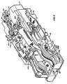
- the gun includes a left hand gun barrel 10L and a right hand gun barrel 10R which are secured to a breech housing 12 of a breech assembly 14.
- the barrels are also constrained by a muzzle clamp assembly 16, a mid-barrel clamp assembly 18,and an aft clamp assembly 22.
- the breech housing 12 is fixed to a receiver housing 26 in a receiver assembly 28.
- a hammer assembly 30 is also fixed to the breech housing 12.
- the breech and receiver housings may be considered together to be the classical "receiver".
- the operating mechanism 32 is mainly disposed within the receiver housing 26 and is included in the receiver assembly 28.
- This operating mechanism includes a rocking lever 34 which is fixed to a central post 36, and which post is journaled for oscillation to the receiver housing 26.
- the rocking lever 34 has a left arm 34L to which is fixed a left post 38L which is journaled to the forward end of a left link 40L, and has a right arm (not visible) to which is fixed a right post (not visible) which is journaled to the forward end of a right link 40R.
- the aft end of the left link 40L is journaled to a left post 42L which is fixed to a left slider 44L.
- the aft end of the right link 40R is journaled to a right post (not visible) which is fixed to a right slider 44R which is identical to the left slider 44L.
- the aft end of each link 40L/R has a projection 40P which is captured in a respective notch in the respective slider 44L/R to capture the link to its respective post 42L/R.
- An additional post 46 is fixed to the rocking lever 34 and is journaled to the forward end of a feeder arm 48.
- the aft end of the feeder arm 48 has a post (not visible) to which is pivotally journaled a tail slider 52.
- the aft end of the slider has a cross-piece 54 which rides in a channel 56 in the receiver housing 26.
- the forward end of the slider 52 has a cam driver 58 with two mutually spaced apart upstanding arms which terminate in mutually opposed cam elements 60L and 60R.
- the cam driver 58 also has a pair of slots 62L and 62R which ride on a pair of tracks (not visible) in the receiver housing.
- the cam driver is thereby constrained to rectilinear reciprocating movement when driven by the feeder arm 48 whose forward end is free to oscillate laterally while reciprocated fore and aft by the rocking lever 34.
- the cam driver drives (not shown here) a drum cam which in turn drives a feed sprocket to advance a belt of linked ammunition transversely through the gun.
- Each full cycle of oscillation of the rocking lever 34 results in the sprocket advancing the belt of ammunition by two rounds.
- the aft ends of the two sliders 44L/R are repectively coupled to two accelerator arms which in turn are respectively coupled to two bolt assemblies.
- Each full cycle of oscillation of the rocking lever 34 results in the fore and aft reciprocation of both bolt assemblies to chamber and fire of two rouds of ammunition.
- Each of the two sliders also cooperates (not shown here) with a respective set of front and rear strippers which serve to strip a round of ammunition from the belt and to place the round on the face of the bolt assembly, and to lock the bolt assembly when the round is chambered.
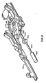
- the external drive assembly includes an electric motor 100, fixed to the receiver housing,whose output shaft 102 is fixed to a bevel pinion gear 104.
- the pinion gear 104 is meshed with two mutually opposed bevel gears 106,108 respectively journaled for rotation about a common axis,in opposite direction.
- a lower cam roller 114 is journaled for rotation on a stub shaft 116 which is carried by the lower gear 108.
- An upper cam roller 110 is journaled for rotation on a stub shaft 112 which is carried by the upper gear 106.
- a shaft 120 is splined to the central post 36 shown in FIG.2, which post is fixed to the rocking lever 34.
- a bifurcated cam follower 118 is fixed to the shaft 120 and its bifurcation projects between the gears 106 and 108 so that the rollers 110 and 114 may ride into and out of the cleft cam following surface 122 of the bifurcation.
- the shafts 102,120, and post 36 are each respectively supported by stationary journals, (not shown).
- Shaft 120 is fixed to a first gear 124 which is meshed with a second gear 126 which is journaled for oscillation about said central axis of said rocking lever and connected to said rocking lever 34, such as by a common shaft 36 fixed to both.
- Second gear 126 may be integratel with said rocking lever 34.
- gear 108 is driven counter-clockwise so that the roller 114 is carried counter-clockwise and swings the bifurcated cam follower 118 with the shaft 120 and the rocking lever 34 clockwise until the roller 114 exits the cleft 112 and the swing of the follower 118 halts.
- gear 104 drives the gear 106 clockwise until it enters the cleft 122 and swings the follower 118, and thereby, the rocking lever 34 counter-clockwise until the roller 110 exits the cleft 122 and the swing of the follower 118 halts until the roller 114 reenters the cleft,and so on.
- This oscillation is communicated to gear 124 and thereby to gear 26 and the post 36 and rocking lever 34.
- FIG.5 An external drive may be substituted as shown in FIG.5.
- This external drive assembly includes a double acting cylinder 500 having a piston 502 whose forward end is connected by a pivotal joint 504 to a journal rod 506 which is journaled on a post 508 which is fixed to and depends from the underside of the rocking lever 34 and is eccentric too the central post 36.
- Aftward movement of the piston 502 pulls the rocking lever through the disposition shown in FIG.5 to bring the left slider 44L into its aft disposition.
- Forward movement of the piston 502 pushes the rocking lever to bring the right slider 44R into its aft disposition.
Landscapes
- Engineering & Computer Science (AREA)
- General Engineering & Computer Science (AREA)
- Transmission Devices (AREA)
- Portable Nailing Machines And Staplers (AREA)
Applications Claiming Priority (4)
| Application Number | Priority Date | Filing Date | Title |
|---|---|---|---|
| US06/793,013 US4700608A (en) | 1985-10-30 | 1985-10-30 | Machine gun |
| US793013 | 1985-10-30 | ||
| US878470 | 1985-12-18 | ||
| US06/878,470 US4726278A (en) | 1985-12-18 | 1985-12-18 | Drive for a machine gun |
Related Parent Applications (2)
| Application Number | Title | Priority Date | Filing Date |
|---|---|---|---|
| EP86114433A Division EP0220630B1 (fr) | 1985-10-30 | 1986-10-17 | Arme automatique |
| EP86114433.5 Division | 1986-10-17 |
Publications (2)
| Publication Number | Publication Date |
|---|---|
| EP0306061A2 true EP0306061A2 (fr) | 1989-03-08 |
| EP0306061A3 EP0306061A3 (fr) | 1990-04-18 |
Family
ID=27121356
Family Applications (2)
| Application Number | Title | Priority Date | Filing Date |
|---|---|---|---|
| EP88115214A Withdrawn EP0306061A3 (fr) | 1985-10-30 | 1986-10-17 | Moteur externe pour canon automatique |
| EP86114433A Expired EP0220630B1 (fr) | 1985-10-30 | 1986-10-17 | Arme automatique |
Family Applications After (1)
| Application Number | Title | Priority Date | Filing Date |
|---|---|---|---|
| EP86114433A Expired EP0220630B1 (fr) | 1985-10-30 | 1986-10-17 | Arme automatique |
Country Status (3)
| Country | Link |
|---|---|
| EP (2) | EP0306061A3 (fr) |
| DE (1) | DE3670902D1 (fr) |
| IL (1) | IL80363A0 (fr) |
Cited By (1)
| Publication number | Priority date | Publication date | Assignee | Title |
|---|---|---|---|---|
| FR2721386A1 (fr) * | 1994-06-16 | 1995-12-22 | Giat Ind Sa | Ensemble de transmission destiné à une arme automatique. |
Family Cites Families (6)
| Publication number | Priority date | Publication date | Assignee | Title |
|---|---|---|---|---|
| FR491908A (fr) * | 1916-01-25 | 1919-06-23 | Alexander Miller Brotherston | Perfectionnements aux mitrailleuses |
| US1477115A (en) * | 1920-09-30 | 1923-12-11 | Gast Carl | Double-barreled machine gun with recoiling barrels |
| GB577338A (en) * | 1944-02-18 | 1946-05-14 | George William Patchett | Improvements in power driven guns or cannons |
| US2972286A (en) * | 1950-04-18 | 1961-02-21 | Frank R Marquardt | Rapid fire gun with two barrels and a plurality of firing chambers |
| US4154142A (en) * | 1977-09-06 | 1979-05-15 | The United States Of America As Represented By The Secretary Of The Army | Externally powered carrier |
| DE3208942C2 (de) * | 1982-03-12 | 1986-02-06 | Rheinmetall GmbH, 4000 Düsseldorf | Maschinenkanone mit zwei zum Vor- und Rücklauf nebeneinander in einem Waffengehäuse angeordneten Waffenrohren |
-
1986
- 1986-10-17 DE DE8686114433T patent/DE3670902D1/de not_active Expired - Lifetime
- 1986-10-17 EP EP88115214A patent/EP0306061A3/fr not_active Withdrawn
- 1986-10-17 EP EP86114433A patent/EP0220630B1/fr not_active Expired
- 1986-10-19 IL IL80363A patent/IL80363A0/xx unknown
Cited By (2)
| Publication number | Priority date | Publication date | Assignee | Title |
|---|---|---|---|---|
| FR2721386A1 (fr) * | 1994-06-16 | 1995-12-22 | Giat Ind Sa | Ensemble de transmission destiné à une arme automatique. |
| US5675111A (en) * | 1994-06-16 | 1997-10-07 | Giat Industries | Transmission assembly with a telescopic universal joint, weapon having such a transmission assembly and method |
Also Published As
| Publication number | Publication date |
|---|---|
| EP0220630A1 (fr) | 1987-05-06 |
| DE3670902D1 (de) | 1990-06-07 |
| EP0306061A3 (fr) | 1990-04-18 |
| IL80363A0 (en) | 1987-01-30 |
| EP0220630B1 (fr) | 1990-05-02 |
Similar Documents
| Publication | Publication Date | Title |
|---|---|---|
| KR101688669B1 (ko) | 무기용 브리치 드라이브 | |
| JP5567584B2 (ja) | 直線状の砲尾または砲弾供給部を備えた武器の砲尾駆動部 | |
| US4700608A (en) | Machine gun | |
| US3834272A (en) | Multibarrel automatic weapon | |
| EP0306061A2 (fr) | Moteur externe pour canon automatique | |
| US4015511A (en) | Feeder | |
| US4747318A (en) | Drive for a machine gun | |
| US4154142A (en) | Externally powered carrier | |
| US4726278A (en) | Drive for a machine gun | |
| CA1280307C (fr) | Entrainement mecanique pour mitrailleuse | |
| US3662646A (en) | Feeder | |
| EP0061204B1 (fr) | Mécanisme de chargement pour mitrailleuse | |
| US3763741A (en) | Cartridge feeding and loading device for light weapons | |
| EP0313793A2 (fr) | Canon automatique | |
| US4203336A (en) | Punch change mechanism for a double pressure pin press | |
| US4400143A (en) | Dual drive pump | |
| DE3216813A1 (de) | Verschluss- lader- anordnung an einer maschinenkanone | |
| DE2743814C3 (de) | Räderkurbelgetriebe für eine mittelachsige Rotationskolbenmaschine | |
| US2504994A (en) | Reversible feed mechanism for machine guns | |
| RU8796U1 (ru) | Устройство для разделки патронов | |
| SU1701959A1 (ru) | Поршневой двигатель | |
| JP3883355B2 (ja) | 機関砲の装填装置 | |
| JPH07174488A (ja) | 遊底駆動機構 | |
| RU2125698C1 (ru) | Револьвер | |
| DE322403C (de) | Rundlaufmotor mit umlaufenden Kolben |
Legal Events
| Date | Code | Title | Description |
|---|---|---|---|
| PUAI | Public reference made under article 153(3) epc to a published international application that has entered the european phase |
Free format text: ORIGINAL CODE: 0009012 |
|
| AC | Divisional application: reference to earlier application |
Ref document number: 220630 Country of ref document: EP |
|
| AK | Designated contracting states |
Kind code of ref document: A2 Designated state(s): CH DE FR GB LI SE |
|
| PUAL | Search report despatched |
Free format text: ORIGINAL CODE: 0009013 |
|
| AK | Designated contracting states |
Kind code of ref document: A3 Designated state(s): CH DE FR GB LI SE |
|
| 17P | Request for examination filed |
Effective date: 19900919 |
|
| 17Q | First examination report despatched |
Effective date: 19911009 |
|
| STAA | Information on the status of an ep patent application or granted ep patent |
Free format text: STATUS: THE APPLICATION IS DEEMED TO BE WITHDRAWN |
|
| 18D | Application deemed to be withdrawn |
Effective date: 19920220 |