EP0306119A2 - Progammkontrollierte, die Position einstellende Vorrichtung - Google Patents
Progammkontrollierte, die Position einstellende Vorrichtung Download PDFInfo
- Publication number
- EP0306119A2 EP0306119A2 EP88301613A EP88301613A EP0306119A2 EP 0306119 A2 EP0306119 A2 EP 0306119A2 EP 88301613 A EP88301613 A EP 88301613A EP 88301613 A EP88301613 A EP 88301613A EP 0306119 A2 EP0306119 A2 EP 0306119A2
- Authority
- EP
- European Patent Office
- Prior art keywords
- central shaft
- cam
- circular arc
- locking
- threads
- Prior art date
- Legal status (The legal status is an assumption and is not a legal conclusion. Google has not performed a legal analysis and makes no representation as to the accuracy of the status listed.)
- Withdrawn
Links
Images


Classifications
-
- B—PERFORMING OPERATIONS; TRANSPORTING
- B25—HAND TOOLS; PORTABLE POWER-DRIVEN TOOLS; MANIPULATORS
- B25B—TOOLS OR BENCH DEVICES NOT OTHERWISE PROVIDED FOR, FOR FASTENING, CONNECTING, DISENGAGING, OR HOLDING
- B25B1/00—Vices
- B25B1/06—Arrangements for positively actuating jaws
- B25B1/10—Arrangements for positively actuating jaws using screws
- B25B1/103—Arrangements for positively actuating jaws using screws with one screw perpendicular to the jaw faces, e.g. a differential or telescopic screw
-
- B—PERFORMING OPERATIONS; TRANSPORTING
- B25—HAND TOOLS; PORTABLE POWER-DRIVEN TOOLS; MANIPULATORS
- B25B—TOOLS OR BENCH DEVICES NOT OTHERWISE PROVIDED FOR, FOR FASTENING, CONNECTING, DISENGAGING, OR HOLDING
- B25B1/00—Vices
- B25B1/06—Arrangements for positively actuating jaws
- B25B1/10—Arrangements for positively actuating jaws using screws
- B25B1/12—Arrangements for positively actuating jaws using screws with provision for disengagement
- B25B1/125—Arrangements for positively actuating jaws using screws with provision for disengagement with one screw perpendicular to the jaw faces
Definitions
- This invention relates to a mechanical program-controlled fast range-adjusting device which can be widely used in arrangements such as the bench vices, the machine vices and the sliding worktables in machine tools wherein the workpieces are required to be quickly clamped (or fed).
- the conventional range-adjusting devices generally use screws and nuts as the driving means.
- the distance (or the relative position) between a movable body (or worktable) and a stationary body (or worktable) is required to be adjusted in a large stroke according to different thicknesses (or positions) of the workpieces, the speed in displacement of the movable body relative to the stationary body will be slow hence the efficiency is decreased.
- An object of the invention is to overcome the aforesaid drawback by employing a mechanical program-controlled position adjusting device which may quickly adjust the distance (or their relative position) between the two bodies according to the different sizes (or relative positions) of workpieces so as to speed the clamping (or feeding)of the working pieces hence to improve the efficiency.
- the position - adjusting device comprises a stationary body, a movable sliding body, a locking mechanism for a central shaft, a clamp force exert ing mechanism and a mechanical program-controlled mechanism.
- an eccentric cam locking mechanism is used; the central shaft is mounted rotatably in the holes of the cam support fixed on the stationary body, said central shaft is provided on itself with a cam, they are connected by the means of a keyway and a guide key; the shape of the holes in the cam support is in the form of a double circular arc; the fitting surfaces between the central shaft and the holes of the cam support are both formed in threads; there are driving threads on left end of the central shaft to engage with the driving threads of a nut on outer of the movable sliding body, said nut is rotated by applying a rotary driving force such that the nut produces an axial displacement to push the sliding body through a plane bearing to clamp workpieces.
- the device according to the invention employes a mechanical program-controlled arrangement which drives the nut once to lock the central shaft first through the eccentric cam locking mechanism then realize the clamping of workpieces through the driving nut; a positioning pin mounted on the central shaft and a stop pin on the movable sliding body may ensure the eccentric cam in a most relaxed position allowing the central shaft to move along the direction of the axis freely relative to the cam support so as to adjust the distance (or their relative position) between the two bodies arbitrarily with a push-and-pull manner in a very short period according to the thickness of a workpiece for attaining a goal to speed the clamping of the workpiece.
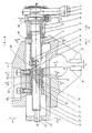
- Fig. 1 shows a bench vice employing the mechanical program-controlled position - adjusting device according to the present invention, comprising the stationary body 21, the movable body 22 able to slide along a guide track in the movable body 22, vice jaws 12 and 14, a locking mechanism for a central shaft, a clamp force exerting mechanism and a program-controlled mechanism; wherein, the locking mechanism for the central shaft comprises the central shaft 20, the cam support 19, the eccentric cam 17, the guide key 16, the positioning pin 10 and the stop pin 26.
- the two ends of the central shaft 20 are supported respectively in the supporting holes 7 and 23 on the front and back vertical plates of the movable body 22.
- the two supporting holes are all long circular holes allowing the central shaft to have a radial movement along a vertical direction.
- the central shaft is provided on itself with an eccentric cam 17 which has a guide key 19 to fit in a keyway 18 on the central shaft 20.
- the central shaft 20 extends through two holes 38 in two walls 40 on the cam support 19. In Fig. 1 there are outer locking threads 25 on the central shaft 20 and driving threads 5 on the left end of the central shaft 20.
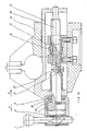
- the cam support 19 is in the form of a saddle (see Fig. 3 and Fig. 4 ) which is fixed on the stationary body 21 by means of the bolts 11.
- the two walls 40 on the support 19 have respectively the concentric holes 38.
- the cross-sectional shape of the holes 38 is formed with two circular arcs, i.e., the upper arc "a" and the lower arc “b” (see Fig. 4 ).
- the center of circle of the upper "a” is 01 and the central angle of the the arc "a” is less than (or equal to) 180.
- the radius of the upper arc "a” is r1 which equals to the thread radius of the locking threads on the central shaft 20.
- the surfaces on the upper arcs "a" of the two holes have respectively the inner locking threads 15 which can engage with the outer locking threads 25.
- the center of circle of the lower arc “b” is 02 which is beneath the center 01 of the upper arc “a” and there is an eccentric distance “e” between the two centers 01 and 02.
- the "e” should be greater than the tooth depth of locking threads 15 and 25.
- the radius r2 of the lower arc "b” should be greater than the thread radius of the outer locking threads 25 on the central 20.
- the eccentric cam 17 is positioned between the two walls 40 of the cam support 19 and is mounted on the central shaft 20 through the guide key 16.
- the cam 17 is a radial eccentric cam and the curve for the cam is comprised of two portions (see Fig. 5 ), wherein one portion is a fast upward stroke curve portion 32 and the other portion is a self-locking curve portion 31 of the cam.
- the design of the two portions of curve should be such that when the central shaft 20 drives the cam 17 to rotate towards the right (the direction of an arrow M in Fig.
- the fast upward stroke curve portion 32 contacts first with the supporting face 24 of the cam support 19, then as the cam 17 continuing in movement causes the central shaft 20 to lift upward vertically allowing the central shaft 20 with its central axial line to lift an distance "e" from a position 02 to a position 01, thus, the outer locking threads 25 on the central shaft 20 will engage preliminarily with the inner locking threads 15 on the surfaces of the arc "a” on the cam support 19, as the central shaft 20 drives the cam 17 to continue its rotation, causing the portion of the self-locking curve 31 to contact gradually with the cam support surface 24 on cam support 19 such that the outer locking threads 25 on the central shaft 20 engages intimately with the inner locking threads 15 on the surface of the upper arc "a” on the hole 38, in the meantime, the cam produces a self-locking action to lock the central shaft 20 with the cam support 19 integrally.
- the clamp force exerting mechanism comprises a handle 1, driving nut 4, a plane bearing 6, a compresssion spring 8 and a gasket 9.
- the handle 1 is mounted on the driving nut 4 and the driving nut 4 engages with the driving thread 5 on the left end of the central shaft 20; the plane bearing 6 is mounted in the bearing seat of the nut 4; the axial displacement of the nut 4 may push the movable body 22 forward, in the direction of an arrow K in Fig. 1, by the plane bearing to clamp the workpiece 28.
- the compression spring 8 is mounted on the central shaft 20 with one end pushing against the inner side of the supporting hole 7 in the movable body 22 and the other end pushing against the pin 10 mounted on the central shaft 20 and the elastic force of the spring 8 holds the movable body 22 permanently to press against the bearing 6.
- the mechanical program-controlled arrangement comprises a ball 3, a spring 2 and a recess 27 on the central shaft wherein, the ball 3 and the spring 2 are fixed on the nut 4 by means of a nut cap; the ball 3 is pressed into the recess 27 (see Fig. 6 ) on the left projection of the central shaft 20; one side wall 33 of the recess 27 inclines more steeply to prevent the ball 3 from escaping and its other side wall 34 inclines more gently.
- the elastic force of the spring 2 shoud be able to continue to rotate the nut 4 after the locking of the central shaft 20 such that the ball 3 can escape from the recess 27 along the side wall 34 (see Fig. 11 ).
- the movable body 22 is provided with a stop pin 26 and the central shaft 20 is provided with a positioning pin 10, the arrangement of them being such that when the range-adjusting device is released, the central shaft 20 is rotated according to a left-hand direction, shown as the arrow N in Fig. 11 . and the positioning pin 10 touches with the stop Pin 26 to cease the rotation of the central shaft.
- the cam 17 should be kept in a most relaxed state relative to the cam support 19, and there is a gap between the cam 17 and the cam supporting surface 24 on the cam support 19 (see Fig. 8 and Fig. 10 ).
- the cam 17 is in a released position (see Fig. 10 ) relative to the supporting surface 24 of the cam support 19.
- the front end and the back end of the central shaft 20 are supported respectively on the lower supporting surfaces 36 and 37 of the supporting holes 7 and 23 on the front and back verticle plates of the movable body 22 (see Fig. 7 ), meanwhile, the positions of the supporting holes 7 and 23 ensure the axis line of the central shaft to be at the center 02 of the lower arc "b" of the holes 38 while the central shaft 20 does not contact with the inner surfaces in two holes 38 of the cam support 19 in any portion (see Fig. 9 ), thus the movable body 22 may be pushed or pulled manually such that the movable body 22 may slide quickly along the guide track in the stationary body 21 with the central shaft 20 to fastly adjust the opening S of the vice jaws according to the size of the workpiece.
- the outer locking threads 25 on the central shaft 20 contacts preliminarily with the inner locking threads 15 on the inner surfaces of two holes 38 in the cam support 19; when the central shaft 20 drives the cam 17 to move continuously, the self-locking curve portion 31 will gradually contact with the cam supporting surface 24 and cuase the outer locking threads 25 of the central shaft 20 to contact intimately with the inner locking thrads 15 on the inner surfaces of two holes 38 (see Fig. 14 and Fig. 15 ) until the cam cannot be rotated again, and at the same time, the cam 17 has become in a self-locking condition to lock the central shaft 20 integrally with the cam support 19 and the stationary body 21.
- the ball 3 pushing against the slide wall 33 with a steeper angle in the recess 27 transmits a driving moment to the central shaft 20 and to the cam 17 through the guide key 16 and the keyway 18 of the central shaft,when the driving moment is greater than the self-locking friction of the cam 17, will drive the central shaft 20 and the cam 17 to rotate along a left-hand direction, direction of the arrow N, and cause both the self-locking curve portion 31 and the fast upward stroke curve portion 32 of the cam 17 to slide along the cam supporting surface 24 of the cam support 19 one after another to bring the cam 17 into a relaxed condition gradually; in the meantime, the central shaft 20 falls from a position in engaging with the inner locking threads 15 of the arc "a" on the cam support 19 (see Fig.
- the central shaft may again move freely along the axial direction to cause the bench vice under a state that its jaw opening can be adjusted arbitrarily, i.e. to restore into the aforesaid state in the first step.
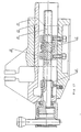
- Fig. 16 shows a modification of the bench vice illustrated in Fig. 1, wherein the ball arrangement has been omitted, but an inner end surface 41 is provided on the driving nut 4, which is suitable for contacting with the driving thread end surface 42 of the central shaft 20 for realizing the program control of first locking the central shaft 20 then clamping the workpiece by means of the moment of friction between two end surfaces 41 and 42.
- Fig. 17 shows a another modification, a two cam machanism (17. 61) spaced a distance on the central shaft 20 may be adopted, for making the force actting on the central shaft 20 to be balanced.
- Fig. 18 also shows a another modification of the bench vice wherein the compression spring 8 shown Fig. 1 is replaced by the extension spring 70 on the end of the central shaft 20. Furthermore, the positioning pin 10 and the stop pin 26 are omitted, while two projected platforms 65 and 64 are formed respectively on the cam 71 and on the movable body 22 (see Fig. 19 ). The effect of the collision and positioning between the two projected platforms are the same as the postioning pin 10 and the stop pin 26 omitted in Fig. 1.
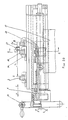
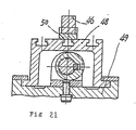
- Fig. 20 shows an embodiment illustrating a hand feed miller employing the fast range-adjusting device according the invention, which can achieve a fast feed in idle stroke, a slow feed in "work feed” and a fast retraction after the workpiece has been processed, wherein, it comprises a movable table 48, a miller bed 49, a mill 47, clamper 50 for a workpiece 46, and a hand wheel 45.
- the workpiece 46 is firmly clamped by the clamper 50 and the clamper 50 is mounted on a T-shaped groove of the movable table 48 (see Fig. 21 ).
- the movable table 48 with the clamper 50 to load or unload the workpiece 46 at a station I, then require to fast feed an idle stroke S q to a station II.
- the movable table 48 loaded with the workpiece 46 begins the "work feed"
- the mill 47 processes the surface J of the workpiece 46
- the movable table 48 with the processed workpiece 46 attains a station III.
- the mill 47 is lifted and the movable table 48 with the processed workpiece 48 retracts quickly to station I, unloading the workpiece and completing an operation cycle.
- the miller employs the fast range-adjusting device according to the present invention.
- the mill 47 When the workpiece has been processed and moved to the station III with the movable table 48, the mill 47 is lifted, then turn the hand wheel 45 in a left-hand direction, or the direction of the arrow N, to drive the central shaft 20 and the cam 17 in rotation, causing the cam 17 from a self-locking position to a relaxed position to release the locking condition of the central shaft 20, subsequently, manually push the movable table 48 along the direction of the arrow H to cause the movable table 48 carrying the workpiece 46 to quickly retract to the station I and unload the workpiece to accomplish an operation.
- the mill 47 When the workpiece has been processed and moved to the station III with the movable table 48, the mill 47 is lifted, then turn the hand wheel 45 in a left-hand direction, or the direction of the arrow N, to drive the central shaft 20 and the cam 17 in rotation, causing the cam 17 from a self-locking position to a relaxed position to release the locking condition of the central shaft 20, subsequently, manually push the movable table 48 along the direction
- an adoptation of the mechanical program-controlled fast range-ajusting device allows to quickly adjust the distance (or the relative position) between the movable body and the stationary body based on different size of the workpieces or their relative positions, hence to improve efficiency.
- the device may have a variety of modifications which should be considered within the scope of the invention.
Landscapes
- Engineering & Computer Science (AREA)
- Mechanical Engineering (AREA)
- Jigs For Machine Tools (AREA)
- Transmission Devices (AREA)
- Gripping Jigs, Holding Jigs, And Positioning Jigs (AREA)
Applications Claiming Priority (4)
| Application Number | Priority Date | Filing Date | Title |
|---|---|---|---|
| CN 87213118 CN87213118U (zh) | 1987-09-04 | 1987-09-04 | 快速夹紧机械程控万能台钳 |
| CN87213118 | 1987-09-04 | ||
| CN87108067 | 1987-11-28 | ||
| CN87108067.2A CN1003115B (zh) | 1987-11-28 | 1987-11-28 | 机械程控式快速调距机构 |
Publications (2)
| Publication Number | Publication Date |
|---|---|
| EP0306119A2 true EP0306119A2 (de) | 1989-03-08 |
| EP0306119A3 EP0306119A3 (de) | 1989-11-23 |
Family
ID=25742389
Family Applications (1)
| Application Number | Title | Priority Date | Filing Date |
|---|---|---|---|
| EP88301613A Withdrawn EP0306119A3 (de) | 1987-09-04 | 1988-02-25 | Progammkontrollierte, die Position einstellende Vorrichtung |
Country Status (4)
| Country | Link |
|---|---|
| US (1) | US4834355A (de) |
| EP (1) | EP0306119A3 (de) |
| JP (1) | JPS6464781A (de) |
| CA (1) | CA1287651C (de) |
Cited By (2)
| Publication number | Priority date | Publication date | Assignee | Title |
|---|---|---|---|---|
| EP0354644A3 (de) * | 1988-08-08 | 1991-03-20 | Chaolai Fan | Schraubmechanismus und Schraubstock |
| EP2314417A1 (de) * | 2009-10-21 | 2011-04-27 | Brockhaus HEUER GmbH | Schraubstock |
Families Citing this family (5)
| Publication number | Priority date | Publication date | Assignee | Title |
|---|---|---|---|---|
| CN1117018A (zh) * | 1994-08-18 | 1996-02-21 | 范朝来 | 快速升降式千斤顶 |
| CN102001003B (zh) * | 2010-10-14 | 2013-04-10 | 濮阳中石集团有限公司 | 吊卡耳孔加工定位装置及使用方法 |
| DE202011103223U1 (de) * | 2011-07-08 | 2012-10-11 | Kuka Systems Gmbh | Arbeitsvorrichtung |
| CN109848854A (zh) * | 2019-04-10 | 2019-06-07 | 苏州友联纺工装备科技股份有限公司 | 一种进给调节机构 |
| US11794802B1 (en) * | 2022-05-17 | 2023-10-24 | Steering Solutions Ip Holding Corporation | Steering column actuator assembly travel stop |
Family Cites Families (7)
| Publication number | Priority date | Publication date | Assignee | Title |
|---|---|---|---|---|
| DE39770C (de) * | J. kenyon, J. barnes und R. W. kenyon in Accrington, Lancaster, England | Schraubenspindel in Verbindung mit dem durch die Patentschrift Nr. 2577 bekannt gewordenen Parallelschraubstock | ||
| US816162A (en) * | 1905-05-08 | 1906-03-27 | Mortimer G Lewis | Bench-vise. |
| US2102602A (en) * | 1935-09-28 | 1937-12-21 | Steel Nut & Joseph Hampton Ltd | Vise |
| US2430458A (en) * | 1945-08-27 | 1947-11-11 | Titan Mfg Company | Automatic screw control |
| US2672776A (en) * | 1952-07-09 | 1954-03-23 | Charles Parker Company | Vise with quick-setting slide |
| DE2848229C2 (de) * | 1978-11-07 | 1980-08-28 | Saurer-Allma Gmbh, 8960 Kempten | Maschinenschraubstock |
| DE2909937A1 (de) * | 1979-03-14 | 1980-09-25 | Roehm Gmbh | Schraubstock, insbesondere maschinen- schraubstock |
-
1988
- 1988-02-12 US US07/155,294 patent/US4834355A/en not_active Expired - Fee Related
- 1988-02-15 CA CA000558898A patent/CA1287651C/en not_active Expired - Lifetime
- 1988-02-24 JP JP63041790A patent/JPS6464781A/ja active Pending
- 1988-02-25 EP EP88301613A patent/EP0306119A3/de not_active Withdrawn
Cited By (2)
| Publication number | Priority date | Publication date | Assignee | Title |
|---|---|---|---|---|
| EP0354644A3 (de) * | 1988-08-08 | 1991-03-20 | Chaolai Fan | Schraubmechanismus und Schraubstock |
| EP2314417A1 (de) * | 2009-10-21 | 2011-04-27 | Brockhaus HEUER GmbH | Schraubstock |
Also Published As
| Publication number | Publication date |
|---|---|
| US4834355A (en) | 1989-05-30 |
| CA1287651C (en) | 1991-08-13 |
| EP0306119A3 (de) | 1989-11-23 |
| JPS6464781A (en) | 1989-03-10 |
Similar Documents
| Publication | Publication Date | Title |
|---|---|---|
| EP0354644A2 (de) | Schraubmechanismus und Schraubstock | |
| US3492886A (en) | Quick acting screw-threaded device | |
| CN109605084B (zh) | 一种型材的加工工装 | |
| US4923185A (en) | Vertical-lift screw drive mechanism | |
| CN114986212B (zh) | 一种机械加工用螺旋式自定心台虎钳压紧装置 | |
| US4139188A (en) | Machine vise | |
| EP0306119A2 (de) | Progammkontrollierte, die Position einstellende Vorrichtung | |
| US3088729A (en) | Quick-acting vises | |
| CN1016524B (zh) | 丝杠垂直升降开合式螺杆传动机构 | |
| CN119857891A (zh) | 一种压铆螺母生产用攻丝设备 | |
| US20240375248A1 (en) | Friction holding stop for a vise | |
| US3915443A (en) | Vise | |
| US3578308A (en) | Vise | |
| JP2694007B2 (ja) | クランプ装置 | |
| US3188077A (en) | Work holding fixture | |
| US5012710A (en) | Device for the automatic engagement of the feed movement and of the return movement of the tool slide of a boring head | |
| JP4063923B2 (ja) | ワークバイスの中間爪ブロック | |
| AU597545B2 (en) | A mechanical program-controlled fast range-adjusting device | |
| CN2649267Y (zh) | 快速凸轮自锁台虎钳 | |
| CN87108067A (zh) | 机械程控式快速调距机构 | |
| CN210335653U (zh) | 一种虎钳 | |
| CN210732229U (zh) | 一种转动式夹持工具 | |
| CN222537491U (zh) | 快速夹紧装置 | |
| CN209902728U (zh) | 一种带有辅助定位装置的主缸体夹紧机构 | |
| CN114178999B (zh) | 一种台虎钳 |
Legal Events
| Date | Code | Title | Description |
|---|---|---|---|
| PUAI | Public reference made under article 153(3) epc to a published international application that has entered the european phase |
Free format text: ORIGINAL CODE: 0009012 |
|
| AK | Designated contracting states |
Kind code of ref document: A2 Designated state(s): DE FR GB NL |
|
| PUAL | Search report despatched |
Free format text: ORIGINAL CODE: 0009013 |
|
| AK | Designated contracting states |
Kind code of ref document: A3 Designated state(s): DE FR GB NL |
|
| 17P | Request for examination filed |
Effective date: 19900421 |
|
| 17Q | First examination report despatched |
Effective date: 19910619 |
|
| STAA | Information on the status of an ep patent application or granted ep patent |
Free format text: STATUS: THE APPLICATION IS DEEMED TO BE WITHDRAWN |
|
| 18D | Application deemed to be withdrawn |
Effective date: 19911230 |