EP0306122A2 - Ceinture de sécurité - Google Patents
Ceinture de sécurité Download PDFInfo
- Publication number
- EP0306122A2 EP0306122A2 EP88303339A EP88303339A EP0306122A2 EP 0306122 A2 EP0306122 A2 EP 0306122A2 EP 88303339 A EP88303339 A EP 88303339A EP 88303339 A EP88303339 A EP 88303339A EP 0306122 A2 EP0306122 A2 EP 0306122A2
- Authority
- EP
- European Patent Office
- Prior art keywords
- locking member
- teeth
- safety belt
- seat
- elongate
- Prior art date
- Legal status (The legal status is an assumption and is not a legal conclusion. Google has not performed a legal analysis and makes no representation as to the accuracy of the status listed.)
- Withdrawn
Links
Images




Classifications
-
- B—PERFORMING OPERATIONS; TRANSPORTING
- B60—VEHICLES IN GENERAL
- B60R—VEHICLES, VEHICLE FITTINGS, OR VEHICLE PARTS, NOT OTHERWISE PROVIDED FOR
- B60R22/00—Safety belts or body harnesses in vehicles
- B60R22/18—Anchoring devices
- B60R22/195—Anchoring devices with means to tension the belt in an emergency, e.g. means of the through-anchor or splitted reel type
-
- B—PERFORMING OPERATIONS; TRANSPORTING
- B60—VEHICLES IN GENERAL
- B60R—VEHICLES, VEHICLE FITTINGS, OR VEHICLE PARTS, NOT OTHERWISE PROVIDED FOR
- B60R22/00—Safety belts or body harnesses in vehicles
- B60R22/18—Anchoring devices
- B60R22/26—Anchoring devices secured to the seat
Definitions
- THE PRESENT INVENTION relates to a safety belt arrangement and more particularly to a safety belt arrangement for use in an automobile such as a motor car.
- a safety belt which has three anchoring points.
- Two anchoring points for the belt are usually located at the base and at the top of the so-called "B-post" of the vehicle, and the third anchoring point is usually located towards the centre of the car adjacent the squab of the seat.
- This third anchoring point usually consists of a buckle adapted to receive a tongue mounted on a part of the saftey belt.
- a safety belt is to retain adqequately a passenger in a motor vehicle involved in an accident, that the safety belt should have the correct geometry relative to the passenger. If the anchoring point located towards the centre of the car is not in the correct position relative to the seat it is possible that the person restrained by the safety belt may "submarine" underneath the lap-portion of the safety belt or may slip out of the safety belt in some other way.
- the seat belt buckle withstands a very large force in an accident situation, and it is thus essential that the seat belt buckle is connected, in some way, to the vehicle chassis, such that the seat belt buckle can withstand such a force without moving in an undesirable manner.
- DE-3243550-A1 discloses a safety belt arrangement in which the height of the buckle is adjusted automatically in response to adjustment of the height of the seat squab.
- the arrangement includes a housing which is securely fixed in position relative to the chassis which defines an elongate slot, the edges of the slot being associated with ratchet teeth.
- a locking assembly can move up and down relative to the slot.
- the locking assembly includes a first member, to which the safety belt buckle is securely attached. This first member can move, with a lost motion relative to a second member that is fixed to the car seat.
- ratchet members adapted to engage with the ratchet teeth which are normally spring biassed to a dis-engaged position but which are moved, by a cam effect, into an engaged position if the seat belt buckle moves upwardly without a simultaneous upward movement of the member attached to the vehicle seat.
- the device is usually in an unlocked condition with the ratchet members spring biassed away from the ratchet teeth and thus the described assembly can usually slide freely up and down the channel as the height of the seat is adjusted.
- the two ratchet members would not engage the teeth associated with the slot but instead might bounce on the tops of the teeth.
- locking would not occur and the buckle would move upwardly. In an accident situation this would be extremely undesirable and could even prove to be fatal.
- the present invention seeks to reduce or obviate the disadvantages found in the prior art.
- a safety belt arrangement comprising an elongate element, the elongate element defining a plurality of ratchet teeth thereon, and a member movable axially of the element and having means thereon adapted to be connected to a seat belt buckle wherein the said member constitutes a locking member, and is provided with teeth thereon adapted to be brought into co-operation with the teeth on the element when a force is applied to the member from the buckle.
- spring biassing means are provided to bias the locking member into a position where the teeth thereon engage the teeth on the element.
- said disengaging means comprise an elongate element connected to the locking member and extending beyond the sides of the element and means provided on the squab of the seat carrying two projecting pegs adapted to engage the ends of the elongate member on upward or downward movement of the squab to cause the locking member to tilt to such a position that the teeth formed thereon are disengaged from the teeth on the element, the locking member is releasably connected to the elongate member, a pre-tensioning device being provided adapted to apply a downward force to the locking member in an accident situation, to separate the locking member from the elongate member and move the locking member downwardly.
- the locking member comprises a protruding peg which extends through an elongate slot formed in the element adapted to be engaged by part of said pre-tensioners.
- the elongate element defines two resilient clips which each grip a pin forming part of the locking member.
- the locking member is provided with two opposed arcuate surfaces, the arcuate surfaces having a common centre of curvature and appropriate radius of curvature, such that the distance between two opposed points on the arcuate faces through the centre of curvature thereof is substantially equal to the distance between two opposed side walls of a channel within the element in which the locking member is slidably mounted.
- the element is a hollow housing which defines a slot with two inwardly directed rows of said teeth directed inwardly towards the interior of the element on either side of said slot the locking member having a portion adapted to extend through the slot and having teeth thereon located on either side of said portion, the portion being adapted to be connected to a seat belt buckle.
- a seat 1 in the front of a motor vehicle has a squab 2 and a back 3.
- the seat is supported on a tubular carriage 4 which slides along a rail (not shown) secured firmly to the floor of the vehicle.
- a buckle 5 of conventional design is located adjacent the squab of the seat 2. This buckle is adapted to receive a tongue present on part of a safety belt, as is conventional.
- the buckle 5 is mounted in position by a mounting arrangement 6 which will be described in greater detail hereinafter.
- the mounting arrangement 6 is such that as the squab 2 of the seat is lowered, so the buckle 5 will also be lowered by a similar amount, and when the squab 2 of the seat is raised, the buckle 5 will also be raised by a similar amount. Since, as will be described, the mounting arrangement 6 is connected to the carriage 4 on which the seat 1 is mounted, the buckle 5 will move forwardly and rearwardly in synchronism with the seat. Thus the buckle 5 will always be in precisely the same position relative to the squab 2 of the seat 1.
- the mounting arrangement 6 consists of an elongate housing 7 which can be seen more clearly in Figure 2.
- the housing 7 is of rectangular section.
- a front face 8 of the housing is provided with an elongate vertical slot or aperture 9 centrally located extending over a substantial proportion of the overall height of the housing 7.
- On side face 10 is provided with a slot 11 extending also over a substantial proportion of the height of the housing.
- the opposed side face 12 is provided with a further slot 13 which extends over substantially the entire height of the housing.
- the walls which define the slot 13 define, on their interior faces, a plurality of projecting teeth 14.
- the entire interior of the housing is hollow, and the housing, adjacent its lower end, is provided with a through bore 15 dimensioned to receive a bolt utilised to secure the housing, in a substantially vertical position, to the rail 4 supporting the seat 1.
- a plate 16 is provided which is mounted on the squab of the seat.
- the plate 16 is provided with two projecting pins 17,18 extending forwardly from the plate 16.
- the plate 16 is of rectangular configuration, and the projecting pin 17 is located adjacent the top left-hand corner, and the projecting pin 18 is located adjacent the bottom right-hand corner of the plate 16 as illustrated in Figure 3.
- the plate may be secured to the squab of the seat in any appropriate manner.
- a locking member 19 is provided, which is a separate component, the locking member being inserted within the interior of the housing 7 and being movable up and down within the interior of the housing 7.
- the locking member 19 consists of an upper portion 20, of generally rectangular configuration, but having rounded side faces as will be described hereinafter.
- the uppermost edge 21 of the portion 20 is provided with a transverse slot 22, and two pins 23,24 are provided which extend across the slot 22.
- a first upper portion of the member 19, adjacent one end of the slot, is of arcuate form 25, having a centre of curvature which is centred on the axis of the pin 24.
- An opposed face 25' of the member 19, is also of arcuate form, again having a centre of curvature coincident with the axis of the pin 24.
- the linear distance between points on the arcuate faces as measured through the axis of the pin 24 is equal to the distance, on the interior of the housing 7, between the interior of the side wall 10, and the interior of the side wall 12, as defined by the points of the teeth 14.
- the locking member 19 is provided, at the base of the region 20, with a projection 26, which extends to one side.
- the projection continues with a central projecting tongue 27 of reduced width.
- the end faces of the projection 26, adjacent the base of the central tongue 27 are provided with teeth or serrations 28. Towards the end of the tongue 27 an aperture 29 is formed.
- a pin 30 Projecting from the front face of the locking member 19, as shown in Figure 4, at a position at the junction of the main portion 20 and the extending portion 26, is a pin 30.
- FIG. 5 illustrates a retaining member adaptd to retain the locking member of Figure 4.
- the retaining member 33 consists of an elongate strip of material.
- the strip of material is provided with recesses forming two releasable catches 34 at spaced positions in one edge of the strip.
- Each catch 34 is formed by two spaced apart parallel slits 35,36, centrally disposed between which is a key-hole-shaped slot 37.
- the nature of the material forming the retaining member 33 is such that the fingers formed between the slits 35,36 and the slot 37 are resilient.
- the dimensioning of the retaining element 33 is such that the strip 33 may be inserted into the slot 22 and the catches 34 may be snapped into engagement with the pins 23 and 24.
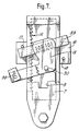
- the plate 16 is located adjacent the housing, with the pins 17 and 18 located adjacent the ends of the retaining element 33 which project through the slots 11 and 13. It can be seen that the pin 17 is located adjacent the upper left-hand end of the retaining element 33, and the pin 18 is located adjacent the lower right-hand end of the retaining element 33 as illustrated in Figure 6.
- the springs 31,32 will bias the locking member 19 back into a locking condition, similar to that as illustrated in Figure 6, but at a lower position within the housing.
- the buckle 5 will thus, at the end of this operation, have exactly the same position as it had initially relative to the seat squab 2, and will be able to withstand any forces applied to it in an accident situation.
- the plate 16 will move upwardly, and the pin 18 will engage the lower right-hand end of the retaining element 33, thus again causing the locking member to pivot about an axis coincident with the axis of the pin 24, as illustrated in Figure 8, with the curved portion 26 of the housing effectively rolling along the tips of the teeth or serrations 14.
- the teeth 28 on the locking member will be disengaged from the teeth 14 on the housing, enabling the locking member to move upwardly.
- the springs 31 and 32 will be resiliently deformed.
- the described embodiment of the invention has been designed so that it can be used, in conjunction with a seat belt pre-tensioner.
- the combination of the forward movement of the passenger and the subsequent stretch of the belt may be sufficient to cause the passenger to come into contact with the windscreen or the steering wheel with a sufficient momentum to injure himself.
- a pre-tensioner applies a tension to the safety belt, thus serving to minimise this effect. This is achieved, in many pre-tensioners, by effecting a downward force on the buckle, such as the buckle 5.
- the locking member 19 is provided with a pin 30 which projects forwardly of the housing 7 through the elongate slot 9. It is intended that this pin is for use with a pre-tensioner arrangement, the pre-tensioner arrangement being designed so that it applies a downward force to the pin 30, should an accident situation arise.
- the downward force applied to the pin 30 is sufficient that the locking member 19 becomes unclipped from the retaining element 33.
- the retaining element 33 receives the pins 23 and 24 between resilient fingers which define between them a key-hole slot 37.
- the force applied to the pin 30 by the envisaged pre-tensioning device causes the locking member to be released from the retaining element 33, and also pivots the locking member so that the teeth 28 are disengaged from the teeth 14.
- the locking member 19 can then move downwardly within the hollow interior of the housing 7 to a relatively low position as illustrated in Figure 9. When in that position any upward force received from the buckle, will be received in the direction of the arrow 39, which will tend to cause the locking member to rotate in a clockwise sense and it will be observed that if this happens the teeth 28 will re-engage with the teeth 14, thus effectively retaining the locking member in its new lower position.
- housing 7 has been described mounted on an element which moves forwardly and backwardly with the seat 1, the housing 7 could be secured directly to an anchoring point on the floor of the vehicle. The housing 7 would then pivot as the seat is moved forwardly and backwardly.
- the elements mounted on the seat to adjust the position of the locking member might need to be slightly modified in such an arrangement.
Landscapes
- Engineering & Computer Science (AREA)
- Mechanical Engineering (AREA)
- Automotive Seat Belt Assembly (AREA)
Applications Claiming Priority (2)
| Application Number | Priority Date | Filing Date | Title |
|---|---|---|---|
| GB878708934A GB8708934D0 (en) | 1987-04-14 | 1987-04-14 | Vehicle seat belt connecting arrangement |
| GB8708934 | 1987-04-14 |
Publications (2)
| Publication Number | Publication Date |
|---|---|
| EP0306122A2 true EP0306122A2 (fr) | 1989-03-08 |
| EP0306122A3 EP0306122A3 (fr) | 1989-07-26 |
Family
ID=10615810
Family Applications (1)
| Application Number | Title | Priority Date | Filing Date |
|---|---|---|---|
| EP88303339A Withdrawn EP0306122A3 (fr) | 1987-04-14 | 1988-04-13 | Ceinture de sécurité |
Country Status (2)
| Country | Link |
|---|---|
| EP (1) | EP0306122A3 (fr) |
| GB (1) | GB8708934D0 (fr) |
Cited By (5)
| Publication number | Priority date | Publication date | Assignee | Title |
|---|---|---|---|---|
| WO1993022156A1 (fr) * | 1992-04-30 | 1993-11-11 | Itt Industries, Inc. | Support de montage rotatif d'une boucle de ceinture de securite pour un dispositif de reglage de siege de vehicule |
| US5507552A (en) * | 1994-01-04 | 1996-04-16 | Itt Corporation | Rotatable seat belt buckle mounting bracket for a vehicle seat adjuster with a catcher bracket buckle brace |
| DE19935616A1 (de) * | 1999-08-03 | 2001-02-15 | Faure Bertrand Sitztech Gmbh | Fahrzeugsitz mit einer Gurtschloßbefestigung |
| US7614660B2 (en) * | 2004-08-26 | 2009-11-10 | Takata-Petri Ag | Belt end fitting device |
| WO2017168103A1 (fr) * | 2016-03-31 | 2017-10-05 | Psa Automobiles S.A. | Structure d'assise reglable d'un siege de vehicule comportant un brin boucle de ceinture de securite |
Family Cites Families (4)
| Publication number | Priority date | Publication date | Assignee | Title |
|---|---|---|---|---|
| US4239260A (en) * | 1979-06-25 | 1980-12-16 | American Safety Equipment Corporation | Adjustable emergency locking buckle anchor |
| DE3216015C2 (de) * | 1982-04-29 | 1986-12-04 | Repa Feinstanzwerk Gmbh, 7071 Alfdorf | Verankerung für das Gurtschloß eines Sicherheitsgurtes |
| DE3243550A1 (de) * | 1982-11-25 | 1984-05-30 | Keiper Automobiltechnik Gmbh & Co Kg, 5630 Remscheid | Verbindungsvorrichtung fuer einen einem verstellbaren fahrzeugsitz zugeordneten sicherheitsgurt |
| GB8608134D0 (en) * | 1986-04-03 | 1986-05-08 | Autoliv Dev | Seat belt pre-tensioning device |
-
1987
- 1987-04-14 GB GB878708934A patent/GB8708934D0/en active Pending
-
1988
- 1988-04-13 EP EP88303339A patent/EP0306122A3/fr not_active Withdrawn
Cited By (9)
| Publication number | Priority date | Publication date | Assignee | Title |
|---|---|---|---|---|
| WO1993022156A1 (fr) * | 1992-04-30 | 1993-11-11 | Itt Industries, Inc. | Support de montage rotatif d'une boucle de ceinture de securite pour un dispositif de reglage de siege de vehicule |
| US5303983A (en) * | 1992-04-30 | 1994-04-19 | Itt Corporation | Rotatable seat belt buckle mounting bracket for vehicle seat adjuster |
| US5507552A (en) * | 1994-01-04 | 1996-04-16 | Itt Corporation | Rotatable seat belt buckle mounting bracket for a vehicle seat adjuster with a catcher bracket buckle brace |
| DE19935616A1 (de) * | 1999-08-03 | 2001-02-15 | Faure Bertrand Sitztech Gmbh | Fahrzeugsitz mit einer Gurtschloßbefestigung |
| US6467849B1 (en) | 1999-08-03 | 2002-10-22 | Bertrand Faure Sitztechnik Gmbh & Co. Kg | Motor vehicle seat with a seatbelt buckle mounting |
| DE19935616C2 (de) * | 1999-08-03 | 2003-12-11 | Faurecia Autositze Gmbh & Co | Fahrzeugsitz mit einer Gurtschloßbefestigung |
| US7614660B2 (en) * | 2004-08-26 | 2009-11-10 | Takata-Petri Ag | Belt end fitting device |
| WO2017168103A1 (fr) * | 2016-03-31 | 2017-10-05 | Psa Automobiles S.A. | Structure d'assise reglable d'un siege de vehicule comportant un brin boucle de ceinture de securite |
| FR3049535A1 (fr) * | 2016-03-31 | 2017-10-06 | Peugeot Citroen Automobiles Sa | Structure d’assise reglable d’un siege de vehicule comportant un brin boucle de ceinture de securite. |
Also Published As
| Publication number | Publication date |
|---|---|
| GB8708934D0 (en) | 1987-05-20 |
| EP0306122A3 (fr) | 1989-07-26 |
Similar Documents
| Publication | Publication Date | Title |
|---|---|---|
| US4239260A (en) | Adjustable emergency locking buckle anchor | |
| US4551889A (en) | Low friction self-locking adjust tongue | |
| US5280959A (en) | Shoulder adjuster | |
| US6467849B1 (en) | Motor vehicle seat with a seatbelt buckle mounting | |
| US6312015B1 (en) | Clamp for retractor belt | |
| EP0608860A1 (fr) | Siège de retenue et de protection pour enfant | |
| EP0693394A2 (fr) | Siège d'enfant pour véhicules et système de ceinture de sécurité pour le siège d'enfant | |
| US20030137180A1 (en) | Four point seat belt restraint system | |
| EP0043430B1 (fr) | Languette réglable et à blocage automatique pour ceinture de sécurité | |
| WO1999024294B1 (fr) | Systeme de retenue servant a augmenter la securite des passagers d'un vehicule automobile, d'un train ou d'un avion | |
| EP3521112B1 (fr) | Dispositif de retenue d'occupant d'un véhicule | |
| DE102010062550A1 (de) | Insassensicherheitssystem | |
| CA1158619A (fr) | Support flottant pour dispositif d'arret sur rappel de ceinture de securite | |
| US6719369B1 (en) | Child seat arrangement on a motor vehicle seat | |
| EP0431198A1 (fr) | Siege de securite de retenue pour petits enfants | |
| US4159120A (en) | Passive restraining system | |
| WO2005102112A2 (fr) | Assise de siege de vehicule a hauteur reglable | |
| US5050907A (en) | Adjustable seat belt anchorage | |
| WO1997024242A1 (fr) | Agencement de ceinture de securite | |
| US5794977A (en) | D-ring height adjuster | |
| US7497474B2 (en) | Cross-car adjustable strap buckle | |
| EP1262383B1 (fr) | Connecteur pour siège de sécurité pour enfants | |
| EP0318127A2 (fr) | Ceinture de sécurité | |
| US5005900A (en) | Automotive seat cushion support | |
| US4909539A (en) | Safety belt system |
Legal Events
| Date | Code | Title | Description |
|---|---|---|---|
| PUAI | Public reference made under article 153(3) epc to a published international application that has entered the european phase |
Free format text: ORIGINAL CODE: 0009012 |
|
| AK | Designated contracting states |
Kind code of ref document: A2 Designated state(s): DE ES FR GB IT |
|
| PUAL | Search report despatched |
Free format text: ORIGINAL CODE: 0009013 |
|
| AK | Designated contracting states |
Kind code of ref document: A3 Designated state(s): DE ES FR GB IT |
|
| 17P | Request for examination filed |
Effective date: 19890720 |
|
| 17Q | First examination report despatched |
Effective date: 19910510 |
|
| RAP1 | Party data changed (applicant data changed or rights of an application transferred) |
Owner name: AUTOFLUG GMBH & CO FAHRZEUGTECHNIK |
|
| STAA | Information on the status of an ep patent application or granted ep patent |
Free format text: STATUS: THE APPLICATION IS DEEMED TO BE WITHDRAWN |
|
| 18D | Application deemed to be withdrawn |
Effective date: 19930127 |