EP0306491B1 - Revetement a l'arc de composes metalliques refractaires - Google Patents
Revetement a l'arc de composes metalliques refractaires Download PDFInfo
- Publication number
- EP0306491B1 EP0306491B1 EP87902978A EP87902978A EP0306491B1 EP 0306491 B1 EP0306491 B1 EP 0306491B1 EP 87902978 A EP87902978 A EP 87902978A EP 87902978 A EP87902978 A EP 87902978A EP 0306491 B1 EP0306491 B1 EP 0306491B1
- Authority
- EP
- European Patent Office
- Prior art keywords
- arc
- cathode
- magnetic field
- track
- anode
- Prior art date
- Legal status (The legal status is an assumption and is not a legal conclusion. Google has not performed a legal analysis and makes no representation as to the accuracy of the status listed.)
- Expired - Lifetime
Links
- 238000000576 coating method Methods 0.000 title claims abstract description 64
- 239000011248 coating agent Substances 0.000 title claims abstract description 47
- 150000002736 metal compounds Chemical class 0.000 title 1
- 239000003870 refractory metal Substances 0.000 title 1
- 229910052751 metal Inorganic materials 0.000 claims abstract description 46
- 239000002184 metal Substances 0.000 claims abstract description 46
- 229910045601 alloy Inorganic materials 0.000 claims abstract description 32
- 239000000956 alloy Substances 0.000 claims abstract description 32
- 238000000034 method Methods 0.000 claims abstract description 27
- 150000002739 metals Chemical class 0.000 claims abstract description 23
- 150000004767 nitrides Chemical class 0.000 claims abstract description 15
- 230000004907 flux Effects 0.000 claims description 27
- 239000000463 material Substances 0.000 claims description 26
- 238000000151 deposition Methods 0.000 claims description 18
- IJGRMHOSHXDMSA-UHFFFAOYSA-N Atomic nitrogen Chemical compound N#N IJGRMHOSHXDMSA-UHFFFAOYSA-N 0.000 claims description 15
- 239000007789 gas Substances 0.000 claims description 12
- 239000010406 cathode material Substances 0.000 claims description 6
- 239000012768 molten material Substances 0.000 claims description 2
- 229910001873 dinitrogen Inorganic materials 0.000 claims 1
- 230000008569 process Effects 0.000 abstract description 8
- 239000008199 coating composition Substances 0.000 abstract description 2
- 239000010936 titanium Substances 0.000 description 23
- 239000000203 mixture Substances 0.000 description 20
- QCWXUUIWCKQGHC-UHFFFAOYSA-N Zirconium Chemical compound [Zr] QCWXUUIWCKQGHC-UHFFFAOYSA-N 0.000 description 19
- 239000002131 composite material Substances 0.000 description 19
- 229910052726 zirconium Inorganic materials 0.000 description 18
- RTAQQCXQSZGOHL-UHFFFAOYSA-N Titanium Chemical compound [Ti] RTAQQCXQSZGOHL-UHFFFAOYSA-N 0.000 description 17
- 229910052719 titanium Inorganic materials 0.000 description 16
- 150000001875 compounds Chemical class 0.000 description 14
- 230000008021 deposition Effects 0.000 description 14
- 230000015572 biosynthetic process Effects 0.000 description 13
- 229910052757 nitrogen Inorganic materials 0.000 description 13
- 238000005275 alloying Methods 0.000 description 9
- 239000002245 particle Substances 0.000 description 9
- 230000001276 controlling effect Effects 0.000 description 8
- 230000003628 erosive effect Effects 0.000 description 8
- 150000002500 ions Chemical class 0.000 description 7
- 230000000694 effects Effects 0.000 description 6
- 238000010891 electric arc Methods 0.000 description 6
- 239000013598 vector Substances 0.000 description 6
- 238000002441 X-ray diffraction Methods 0.000 description 5
- 230000002093 peripheral effect Effects 0.000 description 5
- 230000000875 corresponding effect Effects 0.000 description 4
- 239000007788 liquid Substances 0.000 description 4
- 238000004519 manufacturing process Methods 0.000 description 4
- 230000008859 change Effects 0.000 description 3
- 239000011651 chromium Substances 0.000 description 3
- 238000009826 distribution Methods 0.000 description 3
- 230000005684 electric field Effects 0.000 description 3
- BASFCYQUMIYNBI-UHFFFAOYSA-N platinum Chemical compound [Pt] BASFCYQUMIYNBI-UHFFFAOYSA-N 0.000 description 3
- 230000002829 reductive effect Effects 0.000 description 3
- 239000000758 substrate Substances 0.000 description 3
- 239000013077 target material Substances 0.000 description 3
- XKRFYHLGVUSROY-UHFFFAOYSA-N Argon Chemical compound [Ar] XKRFYHLGVUSROY-UHFFFAOYSA-N 0.000 description 2
- 229910000831 Steel Inorganic materials 0.000 description 2
- ATJFFYVFTNAWJD-UHFFFAOYSA-N Tin Chemical compound [Sn] ATJFFYVFTNAWJD-UHFFFAOYSA-N 0.000 description 2
- 230000009471 action Effects 0.000 description 2
- 238000004458 analytical method Methods 0.000 description 2
- 230000008901 benefit Effects 0.000 description 2
- 230000000739 chaotic effect Effects 0.000 description 2
- 229910052804 chromium Inorganic materials 0.000 description 2
- 239000004020 conductor Substances 0.000 description 2
- 238000010276 construction Methods 0.000 description 2
- 230000002596 correlated effect Effects 0.000 description 2
- 238000005137 deposition process Methods 0.000 description 2
- 238000010292 electrical insulation Methods 0.000 description 2
- 238000010893 electron trap Methods 0.000 description 2
- 230000008030 elimination Effects 0.000 description 2
- 238000003379 elimination reaction Methods 0.000 description 2
- 229910052735 hafnium Inorganic materials 0.000 description 2
- 239000011572 manganese Substances 0.000 description 2
- 229910052750 molybdenum Inorganic materials 0.000 description 2
- 239000000615 nonconductor Substances 0.000 description 2
- 238000005240 physical vapour deposition Methods 0.000 description 2
- 238000012764 semi-quantitative analysis Methods 0.000 description 2
- 238000004544 sputter deposition Methods 0.000 description 2
- 239000010959 steel Substances 0.000 description 2
- 239000000126 substance Substances 0.000 description 2
- 238000003786 synthesis reaction Methods 0.000 description 2
- -1 titanium-hafnium nitride Chemical class 0.000 description 2
- 230000007704 transition Effects 0.000 description 2
- 229910052721 tungsten Inorganic materials 0.000 description 2
- 238000001771 vacuum deposition Methods 0.000 description 2
- OKTJSMMVPCPJKN-UHFFFAOYSA-N Carbon Chemical compound [C] OKTJSMMVPCPJKN-UHFFFAOYSA-N 0.000 description 1
- VYZAMTAEIAYCRO-UHFFFAOYSA-N Chromium Chemical compound [Cr] VYZAMTAEIAYCRO-UHFFFAOYSA-N 0.000 description 1
- XEEYBQQBJWHFJM-UHFFFAOYSA-N Iron Chemical compound [Fe] XEEYBQQBJWHFJM-UHFFFAOYSA-N 0.000 description 1
- PWHULOQIROXLJO-UHFFFAOYSA-N Manganese Chemical compound [Mn] PWHULOQIROXLJO-UHFFFAOYSA-N 0.000 description 1
- ZOKXTWBITQBERF-UHFFFAOYSA-N Molybdenum Chemical compound [Mo] ZOKXTWBITQBERF-UHFFFAOYSA-N 0.000 description 1
- NRTOMJZYCJJWKI-UHFFFAOYSA-N Titanium nitride Chemical compound [Ti]#N NRTOMJZYCJJWKI-UHFFFAOYSA-N 0.000 description 1
- 229910052770 Uranium Inorganic materials 0.000 description 1
- 229910052786 argon Inorganic materials 0.000 description 1
- 238000004364 calculation method Methods 0.000 description 1
- 229910052799 carbon Inorganic materials 0.000 description 1
- 238000000541 cathodic arc deposition Methods 0.000 description 1
- 238000006243 chemical reaction Methods 0.000 description 1
- 238000001816 cooling Methods 0.000 description 1
- 239000000110 cooling liquid Substances 0.000 description 1
- 230000003247 decreasing effect Effects 0.000 description 1
- 239000006185 dispersion Substances 0.000 description 1
- 230000005672 electromagnetic field Effects 0.000 description 1
- 238000005566 electron beam evaporation Methods 0.000 description 1
- 238000010894 electron beam technology Methods 0.000 description 1
- 238000001017 electron-beam sputter deposition Methods 0.000 description 1
- 238000002149 energy-dispersive X-ray emission spectroscopy Methods 0.000 description 1
- 238000005194 fractionation Methods 0.000 description 1
- VBJZVLUMGGDVMO-UHFFFAOYSA-N hafnium atom Chemical compound [Hf] VBJZVLUMGGDVMO-UHFFFAOYSA-N 0.000 description 1
- 238000010438 heat treatment Methods 0.000 description 1
- 239000011261 inert gas Substances 0.000 description 1
- 238000009413 insulation Methods 0.000 description 1
- 229910052743 krypton Inorganic materials 0.000 description 1
- DNNSSWSSYDEUBZ-UHFFFAOYSA-N krypton atom Chemical compound [Kr] DNNSSWSSYDEUBZ-UHFFFAOYSA-N 0.000 description 1
- 239000000696 magnetic material Substances 0.000 description 1
- 238000001755 magnetron sputter deposition Methods 0.000 description 1
- 229910052748 manganese Inorganic materials 0.000 description 1
- 238000002844 melting Methods 0.000 description 1
- 230000008018 melting Effects 0.000 description 1
- 229910001092 metal group alloy Inorganic materials 0.000 description 1
- 238000002156 mixing Methods 0.000 description 1
- 239000011733 molybdenum Substances 0.000 description 1
- RJSRQTFBFAJJIL-UHFFFAOYSA-N niobium titanium Chemical compound [Ti].[Nb] RJSRQTFBFAJJIL-UHFFFAOYSA-N 0.000 description 1
- 230000000737 periodic effect Effects 0.000 description 1
- 238000002294 plasma sputter deposition Methods 0.000 description 1
- 229910052697 platinum Inorganic materials 0.000 description 1
- 239000011253 protective coating Substances 0.000 description 1
- 238000010791 quenching Methods 0.000 description 1
- 230000000171 quenching effect Effects 0.000 description 1
- 230000002441 reversible effect Effects 0.000 description 1
- 238000007789 sealing Methods 0.000 description 1
- 238000000926 separation method Methods 0.000 description 1
- 238000007493 shaping process Methods 0.000 description 1
- 239000007787 solid Substances 0.000 description 1
- 238000004381 surface treatment Methods 0.000 description 1
- 230000002459 sustained effect Effects 0.000 description 1
- 238000010408 sweeping Methods 0.000 description 1
- 230000002194 synthesizing effect Effects 0.000 description 1
- 229910052715 tantalum Inorganic materials 0.000 description 1
- VSSLEOGOUUKTNN-UHFFFAOYSA-N tantalum titanium Chemical compound [Ti].[Ta] VSSLEOGOUUKTNN-UHFFFAOYSA-N 0.000 description 1
- GFNGCDBZVSLSFT-UHFFFAOYSA-N titanium vanadium Chemical compound [Ti].[V] GFNGCDBZVSLSFT-UHFFFAOYSA-N 0.000 description 1
- PMTRSEDNJGMXLN-UHFFFAOYSA-N titanium zirconium Chemical compound [Ti].[Zr] PMTRSEDNJGMXLN-UHFFFAOYSA-N 0.000 description 1
- WFKWXMTUELFFGS-UHFFFAOYSA-N tungsten Chemical compound [W] WFKWXMTUELFFGS-UHFFFAOYSA-N 0.000 description 1
- 239000010937 tungsten Substances 0.000 description 1
- JFALSRSLKYAFGM-UHFFFAOYSA-N uranium(0) Chemical compound [U] JFALSRSLKYAFGM-UHFFFAOYSA-N 0.000 description 1
- 229910052720 vanadium Inorganic materials 0.000 description 1
- XLYOFNOQVPJJNP-UHFFFAOYSA-N water Substances O XLYOFNOQVPJJNP-UHFFFAOYSA-N 0.000 description 1
- 238000004804 winding Methods 0.000 description 1
- 238000004876 x-ray fluorescence Methods 0.000 description 1
Images



Classifications
-
- H—ELECTRICITY
- H01—ELECTRIC ELEMENTS
- H01J—ELECTRIC DISCHARGE TUBES OR DISCHARGE LAMPS
- H01J37/00—Discharge tubes with provision for introducing objects or material to be exposed to the discharge, e.g. for the purpose of examination or processing thereof
- H01J37/32—Gas-filled discharge tubes
- H01J37/32009—Arrangements for generation of plasma specially adapted for examination or treatment of objects, e.g. plasma sources
- H01J37/32055—Arc discharge
-
- C—CHEMISTRY; METALLURGY
- C23—COATING METALLIC MATERIAL; COATING MATERIAL WITH METALLIC MATERIAL; CHEMICAL SURFACE TREATMENT; DIFFUSION TREATMENT OF METALLIC MATERIAL; COATING BY VACUUM EVAPORATION, BY SPUTTERING, BY ION IMPLANTATION OR BY CHEMICAL VAPOUR DEPOSITION, IN GENERAL; INHIBITING CORROSION OF METALLIC MATERIAL OR INCRUSTATION IN GENERAL
- C23C—COATING METALLIC MATERIAL; COATING MATERIAL WITH METALLIC MATERIAL; SURFACE TREATMENT OF METALLIC MATERIAL BY DIFFUSION INTO THE SURFACE, BY CHEMICAL CONVERSION OR SUBSTITUTION; COATING BY VACUUM EVAPORATION, BY SPUTTERING, BY ION IMPLANTATION OR BY CHEMICAL VAPOUR DEPOSITION, IN GENERAL
- C23C14/00—Coating by vacuum evaporation, by sputtering or by ion implantation of the coating forming material
- C23C14/0021—Reactive sputtering or evaporation
-
- C—CHEMISTRY; METALLURGY
- C23—COATING METALLIC MATERIAL; COATING MATERIAL WITH METALLIC MATERIAL; CHEMICAL SURFACE TREATMENT; DIFFUSION TREATMENT OF METALLIC MATERIAL; COATING BY VACUUM EVAPORATION, BY SPUTTERING, BY ION IMPLANTATION OR BY CHEMICAL VAPOUR DEPOSITION, IN GENERAL; INHIBITING CORROSION OF METALLIC MATERIAL OR INCRUSTATION IN GENERAL
- C23C—COATING METALLIC MATERIAL; COATING MATERIAL WITH METALLIC MATERIAL; SURFACE TREATMENT OF METALLIC MATERIAL BY DIFFUSION INTO THE SURFACE, BY CHEMICAL CONVERSION OR SUBSTITUTION; COATING BY VACUUM EVAPORATION, BY SPUTTERING, BY ION IMPLANTATION OR BY CHEMICAL VAPOUR DEPOSITION, IN GENERAL
- C23C14/00—Coating by vacuum evaporation, by sputtering or by ion implantation of the coating forming material
- C23C14/22—Coating by vacuum evaporation, by sputtering or by ion implantation of the coating forming material characterised by the process of coating
- C23C14/24—Vacuum evaporation
- C23C14/32—Vacuum evaporation by explosion; by evaporation and subsequent ionisation of the vapours, e.g. ion-plating
- C23C14/325—Electric arc evaporation
Definitions
- the present invention relates to arc coating of metal targets with alloy hard surface coatings.
- Arc coating films onto objects in which a metal target serves as a source for the coating flux applied in a vacuum ambient atmosphere is known.
- a reactive gas such as nitrogen
- titanium nitride coatings are now routinely produced using arc coating techniques. These physical vapor deposition techniques produce coatings that offer performance advantages over other surface treatments.
- the cathodic arc depositions are a high throughput production process that employs multiple arc evaporators to vaporize the coating material. This is presently done with commercial equipment such as that sold by a number of manufacturers, but problems occur in trying to produce coating alloyed from a composite cathode, because of the lack of the ability to steer the arc properly. The process does not permit forming alloy coatings with composite targets.
- more than one source of coating flux may be used. This can be done, in principle, with electron beam coating sources, sputtering sources and hollow cathode discharge coating sources.
- precise control of the composition of the film deposited requires precise and proportional control of each coating source.
- alloyed source materials may be used. But differential sputtering and differential fractionation of the alloy during the film deposition process usually leads to the formation of a film with a composition which differs from that of the source material. This problem is partly overcome or compensated by using a source material differing in composition from that of the film desired. The needed composition adjustment is found by trial and error. Even this technique requires exact film deposition condition reproducibility to assure film composition reproducibility.
- a method of forming a composite film on a substrate by plasma sputtering is described in US-A-4444635.
- a plasma is formed by ionising a low pressure gas using a glow discharge, and the plasma is confined by magnetic fields to an area above a target plate.
- the target plate is provided with at least two different materials which are bombarded simultaneously by plasma ions on application of an electric field.
- the position of the plasma above the target plate is shifted by varying the magnetic field strength to control the relative proportions of different target materials forming the alloy coating.
- US-A-3956093 describes a planar magnetron sputtering apparatus which includes an additional, variable magnetic field normal to the target plate and which extends throughout the erosion region. By continuously varying the strength of the additional magnetic field, erosion of the target is effected over a larger area allowing a greater proportion of the cathode plate material to be sputtered.
- US-A-4563262 describes an apparatus for depositing a multi-component coating, using an arc discharge, in which the cathode source consists of a number of layers of different metals.
- the cathode spot wanders over the cathode under the influence of a stationary magnetic field whose field lines cut the surface of the cathode at an angle.
- the proportion of each component in the layer depends on the thickness of the metallic layers in the cathode.
- composition reproducibility is a much more difficult problem than with vacuum deposition.
- Arc sources as taught by the Sablev et al. and Snaper patents mentioned above, produce metal vapor for film deposition and metal droplets which are commonly known as macro-particles.
- the proportion of the coating material released in the vapor form and in the droplet form for film deposition varies from material to material and with operating conditions. Reproducible arc coating of alloyed material is therefore very difficult.
- the steered arc coating process allows the precise control over the composition of the film deposited.
- Control over composition is obtained by controlling the time the arc spends in the different regions of a composite target and by eliminating the formation of macro-particles.
- the time the arc spends on each part of a composite target is varied by changing the arc velocity on the cathode surface. Therefore, a reproducible composition of the alloyed film is obtained with steered arc coating when a composite target made of more than one material is used and the composition can be changed by changing the arc velocity.
- the present invention relates to a method and apparatus for permitting the depositing of metal alloys and alloyed compound films in a controlled process, that is low cost and very effective for obtaining reduced macro-particle and macro-particle free films or coatings on surfaces of objects.
- a method of providing an alloy film on a member comprising the steps of providing an anode and a cathode for forming a plasma discharge arc, forming the cathode to have an active target surface, forming an arc between the anode and cathode and providing a magnetic field adjacent the cathode to define a closed arc track, characterised in that said target surface is formed of at least two dissimilar metals in different active surface portions, the active surface portions being adjacent to the anode, the step of forming the arc generates a flux containing a desired proportion of each of the dissimilar metals for forming a deposited coating on the member, and the step of providing the magnetic field defines said closed arc track so that the arc is confined to travel regardless of the materials forming the active surface portions by the presence of the magnetic field on both of the different active surface portions of the cathode, so that as the arc moves in the closed arc track, the arc thereby travels over regions of both of said different surface
- the present method comprises using an arc deposition apparatus utilizing a cathode or target composed of at least two separate metals, each of which form part of the active surface of the cathode.
- the metals forming the cathode are selected to provide for the alloy desired for the coating.
- the metals to be used for alloying are positioned in selected separate locations of the cathode, so that upon forming an arc, and then steering the arc precisely, the amount of the metal flux formed from each of the different metals (more than two can be used) is controlled and the alloy characteristics of the flux being formed for the deposited coating is therefore precisely controlled as well.
- the technique of steering the arc so that it will travel repeatedly over a desired controlled track is disclosed in WO-A-85/03954.
- the arc steering or control apparatus disclosed herein is the same as that disclosed in such earlier application.
- the precise steering enables one to have control of the arc motion over the active surface of the cathode.
- the steering control eliminates periodic arc quenching due to chaotic arc motion beyond the cathode edge (as was a problem in the prior art), and provides for precise control in the alloying process so that the appropriate charactertistics of the deposited alloy film can also be controlled.
- a magnetic field is established, which controls the arc to move in a closed path, and the magnet establishing the magnetic field and thus the arc then may be periodically swept across the cathode surface.
- the arc is made to travel repeatedly over the same track to provide for vapor production from a composite cathode or target made up of at least two metals that are both vaporized and the vapor is combined with a gas to provide a desired alloyed hard compound coating on a part.
- the applied magnetic field for arc control is locally parallel to the active surface of the cathode, which generates a Hall force that acts on the ions as well as the electrons in the vicinity of the cathode. The Hall force leads to cycloidal motion of electrons and massive ions move in the opposite direction.
- the ions are also subject to the prevailing electric field. They are attracted to the active surface of the cathode. Sufficient number of ions impinging on the active surface of the cathode in the vicinity of the original cathode spot at a location consistent with the prevailing electric and magnetic fields induce intense local heating and electron emission in order to render this spot the new cathode spot. The presence of a local magnetic field appropriately disposed at this location can in turn lead to the generation of the next new cathode spot.
- the chaotic sequence of arc spots on the cathode surface of the prior arc deposition devices is replaced with an orderly sequence where all permitted cathode spots lie on a preselected closed path track.
- the length of the preselected track or path of the arc as controlled by the magnetic field is selected so that the cathode material remains molten in the track. That is, the sequence of arc spots in its closed, controlled path returns to the starting point before the cathode material cools sufficiently to solidify.
- Metal vapor emitted from the molten track produces a differential pressure distribution over the cathode surface with higher vapor pressures immediately above the molten track than elsewhere over the cathode surface.
- the magnetic field and the differential vapor pressure generated over the cathode acting separately and in conjunction with each other enables control of the arc motion on the active surface of the cathode.
- the arc voltage is in the range of 27 to 32 volts with a titanium target and 25 to 28.3 volts with zirconium.
- the arc voltage and hence the mean energy of the coating flux is kept relatively higher.
- nitrogen is admitted, the arc voltage is further raised due to the reaction of the nitrogen with the molten metal in the arc track.
- Formation of the metal nitride in the arc track over molten material causes the increase in arc voltage and this metal nitride layer formed in the arc track of the steered arc coating process of the present invention acts to suppress the formation of macro-particles in order to produce good quality films.
- the magnetic field of a solenoidal coil or Helmholtz coil system may be superpositioned on the magnetic field of the main magnet to modify the magnetic field produced on the active surface of the cathode.
- the direction of the current through the coil is chosen to either reinforce or reduce the magnetic field strength vertical to the active surface of the cathode.
- the solenoidal coil or Helmholtz coil system provides additional control over lateral motion of the arc along the path defined by the movable magnet on the active surface of the cathode.
- the magnetic field established controls the movement of the arc in a continuous track.
- the arc is controlled in a path on the cathode surface by the individual and the combined action of the magnetic field and continuous arc discharge when molten tracks are produced (due to high vapor pressure immediately above the arc track). The latter is a result of arc steering and depends on appropriately shaped magnetic fields.
- Arc coating with composite metal targets for alloy coating offers a low cost way for the production of improved coatings for friction and wear applications.
- the control and steering of the arc is essential to insure that the required coating composite is balanced and to insure that the coating can be reproduced reliably on multiple parts.
- the present invention is useful for depositing alloy protective coatings and tool coatings. Continuous coating on the surface of plates or films can also be provided.
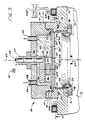
- the apparatus 10 has a housing 11 enclosing a vacuum chamber 12.
- Housing 11 includes a generally flat bottom wall 13 and a flat top wall 14.
- a vacuum source 16 coupled to bottom wall 13 with a tubular member or hose 17 is operable to maintain a vacuum in chamber 12.
- Chamber 12 is evacuated to pressures from below 1.33 x 10 ⁇ 4 to 1.33 x 10³ Pa(10 ⁇ 6 to 10mm of Hg).
- a material deposition head indicated generally at 18 is, as shown, mounted on top wall 14.
- the head 18 can be located entirely within the vacuum chamber 12.
- head 18 has an annular body 19 provided with an inwardly directed annular shoulder 21.
- the body 19 is an electrical insulation ring seated in a circular recess 22 in top wall 14.
- An O-ring 23 located in a groove in top wall 14 maintains a sealing relationship between body 19 and top wall 14.
- a disc cathode or target 24 has an outwardly directed annular lip 24A located on shoulder 21.
- the cathode 24 is made of at least two metals which are to be used for an alloy coating in the process of the present invention.
- the cathode or target may have a base of titanium indicated at 25, with a recess containing a central insert of zirconium indicated at 26.
- the insert of zirconium 26 is removably mounted in the base 25.
- the insert 26 may have a light press fit into a provided recess in the base 25 and then when heated it expands to be securely held in place.
- the insert is provided with an appropriate center threaded vent hole 26A to prevent air from being trapped in the recess in the cathode base 25 and to enable easy change of the insert 26 when it is substantially consumed by the arc erosion process.
- a screw can be threaded into vent hole 26A to provide an element to use for pulling the insert out of the recess in cathode base 25.
- the removable insert 26 may also be made of other material for the deposition of other alloyed materials, such as titanium-hafnium nitride, by simply changing the insert 26, that is by replacing the zirconium insert with a hafnium insert. This way, many different alloys may be produced with the same cathode base 25.
- the two (or more) metals comprising the cathode or target 24 are used for forming an alloy coating on an object 32, such as a turbine blade, a tool bit or the like.
- An electrical insulator support 33 attached to bottom wall 13 locates object 32 in vacuum chamber 12. Other types of supports can be used to hold the object in vacuum chamber. Other types of objects, parts, plates, and the like can be coated with an alloy coating formed from materials 25 and 26 forming cathode 24.
- the active surfaces 27A and 27B of cathode or target materials 25 and 26, respectively, are subject to vacuum in chamber 12 from an opening 28.
- a metal sleeve 29 is located in an annular recess 31 in wall 14 surrounding opening 28. Metal sleeve 29 shields the insulation body 19 to prevent an electrical short between the cathode and an anode 34, caused by the deposition of coating flux from the cathode on the inner cylindrical surface of body 19.
- the anode 34 is a ring or annular anode which extends into opening 28 and is mounted on top wall 14 with a plurality of electrical insulation blocks 36, 37 and 38.
- the anode 34 is thus between the cathode or target 24 and the vacuum chamber 12.
- Anode 34 in plan view preferably has a circular sharp edge 35 facing cathode 24, and an outer cylindrical surface 39 spaced inwardly from annular metal sleeve 29.
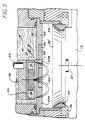
- the cross sectional shape of the ring forming anode 34 is generally triangular as shown in Figure 3.
- the lower portion of the inner surface of anode 34 tapers outwardly to minimize interference with the passage of alloy flux formed from cathode 24 through the center opening of anode 34 to vacuum chamber 12 during operation.
- a cathode carrier 41 made of electrical conducting material, telescopes into body 19 and retains disc cathode 24 on shoulder 21.
- Carrier 41 has a first seal or O-ring 42 engageable with body 19 and a second seal or O-ring 43 engageable with the top of disc cathode 24.
- Carrier 41 has an internal chamber 47 for a cooling liquid 48, such as water.
- a liquid supply line 49 carries liquid from a supply source and a liquid return line 52 carries the liquid out of chamber 47 for continuous cooling.
- An arc control magnet apparatus indicated generally at 53 is located in chamber 47 adjacent the cathode base surface, which is opposite from the active surfaces 27A and 27B. Magnet apparatus 53 is operable to generate a magnetic field on the active surface 27A and 27B of cathode 24 and defining a closed path which an arc will follow. The path is formed where the vertical field vectors go to zero as shown in Figure 6, and preferably this is located at the surface of the cathode in a continuous, closed path defined by the magnetic field. Magnet apparatus 53 has an inverted cup-shaped member 54 having an open end facing cathode 24. Member 54 is a soft magnetic structure having a cylindrical flange 55 forming an outer, peripheral magntic pole located in close relation to the base surface of cathode 24. This base surface is opposite from the active surface 27A and 27B.
- a cylindrical disc magnet member or center magnetic pole 56 is attached to the center portion upper wall of cup member 54.
- the outer surface of magnet member 56 is spaced from the annular sidewall of the cup-shaped member 54 by an annular gap or space 57.
- the cup-shaped member 54 is attached to an electrical insulator mounting plate 58.
- a rotatable shaft 59 is mounted in a bearing assembly 64, projects into chamber 47 and is secured to mounting plate 58.
- Shaft 59 rotatably supports mounting plate 58 and magnet apparatus 53 in the chamber 47 spaced slightly from cathode 24.
- a variable speed electric motor 61 is operable to rotate the shaft 59 as indicated by arrow 62 about the shaft axis 63.
- Magnet apparatus 53 has a central magnetic axis 66 offset from shaft axis 63 whereby on rotation of shaft 59 by motor 61 the magnet apparatus 53 is moved in a continuous circular path. As shown a point of the wall 55 of cup shaped member 54 is displaced with respect to the axis 63 of the shaft 59 so as the shaft is rotated the path of the arc does not overlap the center of the cathode 24 which is shown at 63 in Figure 4.
- the outer edge of the circular path is illustrated at 67 in Figure 4.
- This arrangement enables the sweeping of the closed arc track 60, as defined by the magnet apparatus, in an orbit.
- the arc track 60 represented in dotted lines in Figure 4 is close to the outer wall or pole 54 of the magnetic apparatus, and the dotted line.
- the dotted line 60 also shows the configuration of pole 55.
- the arc thus sweeps an annular area between the center axis 63 of the cathode 27 and an outer circle 70 on the active surfaces 27a and 27B of cathode.
- the active surfaces 27A and 27B of the cathode 24 are the alloy flux producing surfaces for forming the coating.
- the arc track 60 spans the active surfaces of both metals used for alloying, to provide flux from both metals for the coating.
- the amount the arc track overlaps each surface 27A or 27B and the shape of the arc track substantially, but not exclusively controls the amount of flux from each metal.
- the magnetic center or axis 66 of the magnet apparatus 53 can be displaced by different amounts with respect to axis 63, to provide more or less overlap of the arc track in the center of the cathode or target, if desired.
- Electric coil magnet structure can be used in lieu of the permanent magnet to establish the desired magnetic field to control the arc path shape.
- the magnetic field forms a closed path where the vertical magnetic field vectors go to zero, as approximately illustrated by flux paths indicated at 50 in Figure 5, from pole 55 to magnet or pole 56.
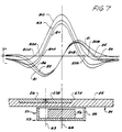
- the vertical and horizontal components of the magnetic field acting perpendicular and parallel to the cathode surface are shown in the upper portion of Figure 6.
- the upper curve 80 shows the magnitude of the vertical component of the magnetic field across the cathode 24 in relation to the magnetic apparatus 53.
- the second curve 81 depicts the magnitude of the horizontal or parallel component of the magnetic field acting on the cathode surface.
- the magnitudes of the field strengths perpendicular (the vertical component) and parallel (the horizontal component) to the cathode surface are determined by the choice of the permanent magnetic material of magnet 56 and the spatial distribution is determined by the dimensions and location of the pole piece 54.
- the vertical component of the magnetic field changes sign at the location determined by the wall 55 of the cup shaped member or pole piece 54 as indicated at 80A and 80B.
- the arc track or trajectory that is the track of a series of arc spots formed by ion activity or continuous arc discharge when a molten track is formed, is controlled to be an annular track substantially as shown at 60, that is adjacent to the pole 55.
- the shape of the outer peripheral pole 55 in large part determines the shape of the arc track.
- the radial location of the arc track with respect to magnetic central axis 66, where the vertical field vectors are substantially zero can be controlled to be within the cathode 24 and substantially on active surfaces 27A and 27B.
- the horizontal component of the magnetic field is not zero as shown by vertical lines 81A and 81B in Figure 6.
- the magnitude of the horizontal component of the magnetic field on the cathode surface along the arc path 60 and the material of the cathode 24 jointly determine the arc velocity.
- the magnitude of the horizontal component of the magnetic field on the cathode surfaces 27A and 27B is carefully selected. Formation of the molten track tends to produce a stable and continuous arc discharge. This is a preferred steered arc coating mode to minimize and eliminate macro-particle formation in the coated films.
- the slope of the vertical component of the magnetic field, at points 80A and 80B where curve 80 changes sign on the cathode surface is varied by the choice of the permanent magnet material 56, the dimensions of the wall 55 of cup shaped member 54 and the location of the wall 55 with respect to the active surfaces 27A and 27B on the cathode 24.
- Shallow slopes (less vertical slopes in regions adjacent 80A and 80B) tend to produce lateral arc motion or arc "jiggle" as the arc travels around the preferred arc track or trajectory.
- a sharp (narrow) arc track and a continuous molten arc track on the cathode surfaces 27A and 27B are then difficult to produce and hard compound films deposited under these conditions show decreased macro-particle formation but not their complete elimination.
- Macro-particles in the film deposited are not desirable.
- a distinct minimum in the vertical component of the magnetic field of sufficiently large magnitude, as shown at 80C and 80D in Figure 6, is found to produce tight control over arc motion and to prevent arc movement in the transverse direction.
- Stable arc tracks as close as possible to 0.51mm (0.020 inch) in width are highly desired for macro-particle elimination when hard compound films are deposited with arc coating.
- an electrical coil or winding 68 is mounted on top wall 14 concentric with shaft axis 63.
- Coil 68 surrounds head 18 and is located generally in the plane of cathode 27.
- Coil 68 is a solenoidal coil operable to cancel out or greatly reduce the vertical magnetic field components of magnet apparatus 53, and generate a purely parallel magnetic field at preferred locations on the active surface of the cathode 24.
- the super-position of the coil field on the magnet field of magnet apparatus 53 results in tighter control over closed path where the vertical field vectors go to zero or to define the arc track 60.
- Lines 69 connect coil 68 to a suitable variable current control 69A.
- the control can be a manual current control device or a computer controller that can be programmed to regulate the current to coil 68.
- a current passing through coil 68 modifies the main magnetic field produced on the active surfaces 27A and 27B of cathode 24 by magnet apparatus 53 and controls the velocity of the arc in its path or track.
- the direction of the current through coil 68 is chosen to reinforce or reduce the magnetic field strength normal to the cathode active surface 27 of cathode 24.
- the vertical magnetic field component of the field from magnet apparatus 53 can be cancelled, greatly reduced or can be increased by the superposition of a magnetic field generated by solenoid 68. This results in a tighter control over the arc track.
- Energizing coil 68 does not significantly change the arc path dimensions which are primarily controlled by wall 55 of the pole 54.
- the field created by passing current through the solenoidal coil 68 also affects the horizontal component of the total magnetic field. However, the effect is not very large and hence the arc velocity is not significantly affected, when coil 68 is placed on or near the plane of the active surfaces 27A and 27B of cathode 24.
- the uppermost curve 80 again shows the vertical field component due to the permanent magnet assembly 53 alone.
- the curve 83 shows the effect on the vertical field component of the magnetic field over the cathode surface by the superposition of a first electrically generated magnetic field acting in opposition to the magnetic field of the arc control magnet apparatus by passing a first current through coil 68.
- the curve 84 shows the effect of a second greater current through coil 68.
- the current used to generate the electro-magnetic fields can be changed to obtain different vertical field component distributions.
- the curve 81 shows the horizontal field component with only magnet apparatus 53.
- Curve 85 is the horizontal component with the same first current as for curve 83 and curve 86 is the horizontal field for the same second current as for curve 84.
- the slope of lines 83 and 84 where they cross zero, as at points 83A, 83B and 84A, 84B can be increased (made more vertical) as shown.
- a second coil 68A may be mounted on bottom wall 13 of the housing 11 in axial alignment with coil 68.
- Lines 69B connect coil 68A to a power supply and current control circuit or device, which may be the same as the control 69A for coil 68, and a power supply.
- Coils 68 and 68A may be concurrently used as a Helmholtz coil system to selectively modify the magnetic field produced on each of the active surfaces 27A and 27B of the cathode or target 24. This is an alternate means of controlling the magnetic field on the active surfaces 27A and 27B of cathode 24.
- This arrangement when coils 68 and 68A are properly selected, permits controlling the field to increase velocity of the arc in portions of the arc track with respect to other portions, so the amount of flux generated from each metal forming the cathode or target is controlled.
- a suitable power supply 73 can be connected to anode 34 through a line 71.
- Power supply 73 includes a variable current control 73A.
- Supply 73 is also connected to an electrical conductor 74 leading to cathode carrier 41 and thereby connecting cathode 24 to power in a known arrangement. Varying the arc current changes the arc velocity in the arc track as well. This adjustment controls the composition by changing the arc current while the cathode composition and construction, the magnet field controlling the arc shape, and the target dimensions remain constant.
- Housing 11 ( Figure 1) has a valve 78 to allow the introduction of a suitable gas, such as nitrogen, as well as other desired gases and gas mixtures, into vacuum chamber 12.
- a second valve 77 can be a leakage valve used to adjust or release the vacuum in chamber 12.
- the central magnet member 56 carried by the soft magnetic member 54 produces a circular symmetric closed fringing magnetic field between the outer pole 55 and the center pole 56 as shown.
- the geometry of anode 34 and cathode 24 are such that the magnetic field produced by the magnetic apparatus 53 is generally normal to the electric field generated between cathode 24 and annular anode 34 when an appropriate electrical potential difference is applied to the anode and cathode.
- the magnetic apparatus 53 acts as an electron trap for electrons emitted from the active cathode surfaces 27A and 27B when a high voltage is applied to the cathode 24. A negative potential is applied to cathode 24. In the absence of a magnetic field in the vicinity of the cathode 24, a weak discharge is induced within the vacuum chamber.
- Inert gases such as Argon and Krypton
- the discharge current is a function of gas species, chamber pressure, and applied voltage.
- the arc produced between anode 34 and cathode 24 is steered by the magnetic field of magnet apparatus 53 (and coil 68 or coils 68 and 68A when desired) and sustains itself indefinitely.
- the arc track or trajectory is determined by the shape of pole or member 56 and the annular ring configuration of member 54.
- the arc track 60 is a circular path on active surface 27 of cathode 24.
- the arc track may take rectangular, elliptical or other desired shapes.
- Intense arc erosion (and thus formation of alloying flux) occurring along the arc track 60 would result in the formation of grooves on the active surfaces 27A and 27B of cathode 24 if the magnetic apparatus 53 stayed in one position.
- the erosion and flux forming action is distributed more evenly over the surfaces by rotating the magnet apparatus 53 around axis 63.
- the rotation of the magnet apparatus 53 causes the arc track 60 defined by the magnet apparatus 53 to trace a cycloidal path on the active surface 27 of cathode 24.
- pole 55 and cathode 24 may be chosen so as to cause the arc path and hence arc erosion of the cathode to be confined to an annular, ring-shaped region between the axis 63 and circles 70 in Figure 4 of the active surfaces 27A and 27B of cathode 24.
- the inner radius of this ring region may be zero, but as shown, a non-zero radius is used. It can be varied by the appropriate choice of magnetic axis 66 and the shape and dimensions of pole 56.
- the velocity of the arc can be changed by adjusting arc current using current control 73A. Also, using adjustable current control 69A to selectively control current to coils 68 and 68A, the velocity can be controlled in certain portions of the arc track.
- Rectangular arc tracks and connected part circular arc tracks may be realized with appropriate variations in the geometry of pole 55.
- Other closed arc tracks such as triangular and elliptical, can be used.
- the condition to be met to fulfill generation of a closed arc track, such as track 60, is the presence of continuously turning magnetic field vectors where the vertical component of the field vectors go to zero on the active surfaces 27A and 27B of cathode 24.
- the arc track can also be made to sweep over major portions of the active surfaces 27A and 27B of the cathode 24 to insure erosion of the alloying materials in composition target or cathode 24 in the proper proportion of the two different metals 25 and 26. This insures high cathode material utilization efficiency.
- Ion activity and differential vapor pressures generated cause the arc spot to move in its defined arc track as controlled by the magnetic field.
- the precise control achieved permits proper proportioning of the alloying metals forming the flux for deposition.
- Admitting active gases such as nitrogen through valves 77 and 78 permits forming alloy nitride coating.
- the metal target or cathode serves as a source for the coating flux, and by reacting the flux derived from two different metals, selected from a suitable group, with a reactive gas such as nitrogen, titanium zirconium nitride coatings are easily produced. Alloy nitrides are expected to yield properties superior to those obtainable with mono-nitrides.
- This method and apparatus shows that alloy nitrides using arc coating techniques can be deposited at low cost, and relatively simply, as long as the path of the arc can be precisely controlled to control the proportion of the alloying metals in the flux for the deposited layer, and of course the control of the arc into a desired path can determine the rate with which deposition occurs so that the proper alloying effect is obtained.
- Composite targets of titanium and zirconium, as shown in Figures 3 and 5 were fabricated with a zirconium insert in a titanium base to produce mixed or alloyed nitrides.
- Nitrides of both these metals have a cubic NaCl-type lattice and are known to possess continuous solid solubility. Alloyed nitrides of the form (Ti x Zr y )N are expected to exhibit solution hardening characteristics and hence superior hardness and tribological properties. Synthesis of such alloyed nitride is therefore of considerable technical and commercial interest.
- the work function of titanium (3.95 electron volts) is lower than that of zirconium (4.12 to 4.21 eV).
- the melting temperature of titanium is also lower than zirconium. It is therefore virtually impossible to obtain controlled alloy nitride film production with a composite target when random arc coating processes are used. The arc tends to remain substantially on the surface of the material producing copious vapor flux at a lower temperature. In the present example, this is titanium.
- the arc is forced to reside for controlled durations of time in the zirconium and in the titanium portions of the target.
- Residence time control is obtained by measuring the arc velocity in titanium and zirconium under a given set of arc coating conditions, i.e., the arc current and the transverse magnetic field strength on the cathode surface. Using this information the size of the zirconium insert is selected in relation to the size of titanium part and the peripheral length of the arc track used to steer the arc.
- (Ti x Zr y )N films were deposited experimentally using the composite cathode shown in Figure 3, and the steered arc coating process.
- Steered arc coated samples produced with an arc current of 50 amperes exhibited, in X-ray diffraction analysis, first and second diffraction peaks at 35.5 and 41.5 degrees indicating the formation of (Ti x Zr y )N.
- Values of x and y corresponding to this deposited alloy compound will vary and may be determined by known X-ray fluorescence analysis and other techniques.
- Semi-quantitative analysis using an energy dispersive spectrometer yielded atomic abundances of 25.5% zirconium and 3.3% titanium for the film deposited on a steel substrate.
- the alloy compound is atomically a little richer in titanium than zirconium.
- films produced at an arc current of 75 amperes yielded X-ray diffracton peaks at 35, 41, and 59.9 degrees.
- Semi-quantitative analysis yielded relative atomic abundances of 29.67% zirconium and 18.7% titanium in films deposited on a steel substrate. This film is richer in zirconium than titanium, although a cathode having the same construction was used.
- Peaks corresponding to pure ZrN and TiN could not be detected in both the samples produced (X-ray diffraction analysis).
- An alloyed nitride corresponding to (Ti x Zr y )N was produced and verified the formation of the single phase nitride by X-ray diffraction analysis.
- the present invention permits synthesizing alloyed hard compounds (single phase materials) of mutually soluble hard compounds using a single composite cathode or target, the composition can be controlled through the choice of dimensions of the titanium and zirconium parts of the composite target or by changing the arc current used in the process (the cathode size, the magnetic steering means and arc track dimensions remain constant).
- the arc velocity in each part of the target also can be controlled by changing the field strength of the magnetic arc steering means.
- alloyed hard compounds such as titanium hafnium nitride (Ti-Hf-N), titanium-vanadium nitride (Ti-V-N), titanium niobium nitride (Ti-Nb-N), titanium tantalum nitride (Ti-Ta-N) partially soluble and therefore capable of producing "dispersion hardened” alloy compounds may be used having the same cathode base or body 25 and replaceable insert 26. Alloys of these forms may also permit precipitation-hardened alloy compounds with superior hardness and wear resistance.
- the alloying is not limited to Ti(M)N, where (M) can stand for chromium (Cr), molybdenum (Mo), tungsten (W), uranium (U), manganese (Mn), iron (Fe), and platinum (Pt) group of metals but also compounds of the form Zr(M)N, Hf(M)N, V(M)N, Ta(M)N, Cr(M)N, Mo(M)N, W(M)N can be formed.
- the steered arc, and the control of the arc path is essential to a sure coating composition and reproducibility, because the various factors that are controllable, such as power levels to the anode and cathode, the size of the cathode, and the relative position and volume of the respective metals being used for the alloy, and other physical factors can be easily controlled, but unless the arc path is predetermined, repeatable, and controlled in a desired manner, the amount of the respective metals in the flux being generated by the arc can vary and thus make it impossible to properly form the coating.
Landscapes
- Chemical & Material Sciences (AREA)
- Engineering & Computer Science (AREA)
- Organic Chemistry (AREA)
- Materials Engineering (AREA)
- Mechanical Engineering (AREA)
- Metallurgy (AREA)
- Chemical Kinetics & Catalysis (AREA)
- Physics & Mathematics (AREA)
- Plasma & Fusion (AREA)
- Analytical Chemistry (AREA)
- Physical Vapour Deposition (AREA)
- Arc Welding In General (AREA)
- Manufacture Of Alloys Or Alloy Compounds (AREA)
- Coating By Spraying Or Casting (AREA)
Abstract
Claims (6)
- Procédé de formation d'un film d'alliage sur une pièce (32), comprenant les étapes consistant à disposer une anode (34) et une cathode (24) de manière à produire un arc de décharge de plasma, à former la cathode (24) de sorte qu'elle présente une surface cible active (27A, 27B), à produire un arc entre l'anode et la cathode et à créer un champ magnétique au voisinage immédiat de la cathode pour définir un trajet fermé (60) de l'arc,
caractérisé en ce que
ladite surface cible (27A, 27B) est formée d'au moins deux métaux dissemblables (25, 26) dans différentes parties (27A, 27B) de la surface active, ces parties de la surface active étant adjacentes à l'anode (34);
l'étape de production d'un arc engendre un flux contenant une proportion désirée de chacun des métaux dissemblables (25, 26) pour former un revêtement déposé sur la pièce (32),
et l'étape de création du champ magnétique définit ledit trajet fermé (60) de l'arc de sorte que l'arc soit obligé par la présence du champ magnétique, quels que soient les matières formant les parties (27A, 27B) de la surface active, de cheminer sur les deux parties différentes (27A, 27B) de la surface active de la cathode (24), ce qui fait que tandis que l'arc se déplace sur le trajet fermé (60), il passe par des régions des deux parties différentes (27A, 27B) de la surface, la longueur du trajet de l'arc étant définie, en fonction de la vitesse de cheminement de l'arc de sorte que les matières de la cathode restent à l'état fondu dans le trajet (60) de l'arc tandis que l'arc chemine sur ledit trajet (60) pendant le fonctionnement. - Procédé selon la revendication 1, dans lequel ladite cathode (24) présente une surface active généralement plate, une première partie (27B) de la surface, faite d'un métal (26), étant concentrique à l'axe central (63) de ladite cathode et une seconde partie (27A) de la surface, faite d'un second métal (25), entourant la première partie (27B) de la surface.
- Procédé selon la revendication 1 ou 2, dans lequel on fait tourner ledit trajet (60) de l'arc autour de l'axe central (63), ledit trajet de l'arc restant à cheval sur les deux parties (27A, 27B) de la surface pendant chacune de ses rotations.
- Procédé selon l'une quelconque des revendications 1 à 3, comprenant l'étape consistant à disposer des seconds moyens magnétiques séparés (68) pour modifier le champ magnétique mentionné en premier, afin d'effectuer une commande de l'arc en augmentant la pente de la composante verticale (80) du champ magnétique au moment où la composante verticale passe par zéro (80A, 80B).
- Procédé selon l'une quelconque des revendications 1 à 4, dans lequel l'anode (34) est une anode de type annulaire et il est prévu une chambre à vide (12) ouverte en direction de ladite anode de type annulaire (34) et de la cathode (24), ledit flux engendré passant à travers ladite anode (34) pour pénétrer dans ladite chambre à vide (12), le procédé comprenant l'étape consistant à introduire un gaz désiré dans la chambre à vide (12) pour qu'il se combine avec le flux pour déposer un film sur une pièce (32) supportée dans cette chambre.
- Procédé selon la revendication 5, comprenant l'étape consistant à introduire du gaz azote dans la chambre a vide (12) pour former une couche de nitrure de métal sur la matière fondue dans le trajet (60) de l'arc.
Applications Claiming Priority (2)
| Application Number | Priority Date | Filing Date | Title |
|---|---|---|---|
| US84872086A | 1986-04-04 | 1986-04-04 | |
| US848720 | 1986-04-04 |
Publications (3)
| Publication Number | Publication Date |
|---|---|
| EP0306491A1 EP0306491A1 (fr) | 1989-03-15 |
| EP0306491A4 EP0306491A4 (fr) | 1990-01-08 |
| EP0306491B1 true EP0306491B1 (fr) | 1994-03-09 |
Family
ID=25304090
Family Applications (1)
| Application Number | Title | Priority Date | Filing Date |
|---|---|---|---|
| EP87902978A Expired - Lifetime EP0306491B1 (fr) | 1986-04-04 | 1987-04-01 | Revetement a l'arc de composes metalliques refractaires |
Country Status (7)
| Country | Link |
|---|---|
| US (1) | US4839011A (fr) |
| EP (1) | EP0306491B1 (fr) |
| JP (1) | JP2571948B2 (fr) |
| AU (1) | AU612319B2 (fr) |
| CA (1) | CA1272910A (fr) |
| DE (1) | DE3789307T2 (fr) |
| WO (1) | WO1987005948A1 (fr) |
Families Citing this family (29)
| Publication number | Priority date | Publication date | Assignee | Title |
|---|---|---|---|---|
| US5298136A (en) * | 1987-08-18 | 1994-03-29 | Regents Of The University Of Minnesota | Steered arc coating with thick targets |
| DE3825399C5 (de) * | 1988-07-23 | 2005-05-12 | Cemecon Ag | PVD- oder Plasma- CVD-Beschichtung |
| US5254359A (en) * | 1989-06-02 | 1993-10-19 | Air Products And Chemicals, Inc. | Method of forming titanium nitride coatings on carbon/graphite substrates by electric arc thermal spray process using titanium feed wire and nitrogen as the atomizing gas |
| JPH04236770A (ja) * | 1991-01-17 | 1992-08-25 | Kobe Steel Ltd | 真空アーク蒸着のアークスポットの制御方法及び蒸発源 |
| US5487822A (en) * | 1993-11-24 | 1996-01-30 | Applied Materials, Inc. | Integrated sputtering target assembly |
| US5433835B1 (en) * | 1993-11-24 | 1997-05-20 | Applied Materials Inc | Sputtering device and target with cover to hold cooling fluid |
| DE4410466C1 (de) * | 1994-03-25 | 1995-09-14 | Balzers Hochvakuum | Targethalterung, Target und ihre Verwendung |
| CH689558A5 (de) * | 1995-07-11 | 1999-06-15 | Erich Bergmann | Bedampfungsanlage und Verdampfereinheit. |
| US5985115A (en) * | 1997-04-11 | 1999-11-16 | Novellus Systems, Inc. | Internally cooled target assembly for magnetron sputtering |
| GB9722649D0 (en) | 1997-10-24 | 1997-12-24 | Univ Nanyang | Cathode ARC source for metallic and dielectric coatings |
| US6340415B1 (en) | 1998-01-05 | 2002-01-22 | Applied Materials, Inc. | Method and apparatus for enhancing a sputtering target's lifetime |
| JP2002525431A (ja) * | 1998-09-14 | 2002-08-13 | ユナキス・トレーディング・アクチェンゲゼルシャフト | アーク蒸化室用ターゲット配置 |
| GB9910842D0 (en) | 1999-05-10 | 1999-07-07 | Univ Nanyang | Composite coatings |
| DE19924094C2 (de) * | 1999-05-21 | 2003-04-30 | Fraunhofer Ges Forschung | Vakuumbogenverdampfer und Verfahren zu seinem Betrieb |
| US6335536B1 (en) * | 1999-10-27 | 2002-01-01 | Varian Semiconductor Equipment Associates, Inc. | Method and apparatus for low voltage plasma doping using dual pulses |
| GB2377228C (en) * | 2000-07-27 | 2010-01-08 | Trikon Holdings Ltd | Magnetron sputtering |
| CN100355933C (zh) * | 2001-03-27 | 2007-12-19 | 特克尼克基业 | 具有用于较大表面积的靶的强力磁引导装置的电弧蒸发器 |
| KR100390849B1 (ko) * | 2001-06-30 | 2003-07-12 | 주식회사 하이닉스반도체 | 하프늄산화막을 구비하는 캐패시터의 제조 방법 |
| US6984675B2 (en) * | 2001-11-28 | 2006-01-10 | Resolution Specialty Materials Llc | Formaldehyde-free binder compositions for simultaneous warp sizing and coloration of filament yarns |
| TWI269815B (en) * | 2002-05-20 | 2007-01-01 | Tosoh Smd Inc | Replaceable target sidewall insert with texturing |
| TWI226082B (en) * | 2003-12-16 | 2005-01-01 | Promos Technologies Inc | Physical vapor deposition process and apparatus thereof |
| CH697552B1 (de) * | 2004-11-12 | 2008-11-28 | Oerlikon Trading Ag | Vakuumbehandlungsanlage. |
| US20100143232A1 (en) * | 2006-06-21 | 2010-06-10 | Benedict James Costello | Metal binary and ternary compounds produced by cathodic arc deposition |
| US7879203B2 (en) * | 2006-12-11 | 2011-02-01 | General Electric Company | Method and apparatus for cathodic arc ion plasma deposition |
| US8968528B2 (en) * | 2008-04-14 | 2015-03-03 | United Technologies Corporation | Platinum-modified cathodic arc coating |
| JP5649308B2 (ja) * | 2009-04-28 | 2015-01-07 | 株式会社神戸製鋼所 | 成膜速度が速いアーク式蒸発源及びこのアーク式蒸発源を用いた皮膜の製造方法 |
| JP6403269B2 (ja) * | 2014-07-30 | 2018-10-10 | 株式会社神戸製鋼所 | アーク蒸発源 |
| DE102017213404A1 (de) * | 2017-08-02 | 2019-02-07 | Fraunhofer-Gesellschaft zur Förderung der angewandten Forschung e.V. | Anordnung zur Beschichtung von Substratoberflächen mittels elektrischer Lichtbogenentladung |
| RU2716385C1 (ru) * | 2019-09-30 | 2020-03-11 | федеральное государственное бюджетное образовательное учреждение высшего образования "Ульяновский государственный технический университет" | Способ получения износостойкого покрытия для режущего инструмента |
Citations (1)
| Publication number | Priority date | Publication date | Assignee | Title |
|---|---|---|---|---|
| WO1985003954A1 (fr) * | 1984-03-02 | 1985-09-12 | Regents Of The University Of Minnesota | Deposition regulee de materiau par arc sous vide, procede et appareil |
Family Cites Families (7)
| Publication number | Priority date | Publication date | Assignee | Title |
|---|---|---|---|---|
| US3625848A (en) * | 1968-12-26 | 1971-12-07 | Alvin A Snaper | Arc deposition process and apparatus |
| SU363375A1 (ru) * | 1970-03-20 | 1979-01-10 | Sablev L P | Электродуговой испаритель металлов |
| US3956093A (en) * | 1974-12-16 | 1976-05-11 | Airco, Inc. | Planar magnetron sputtering method and apparatus |
| DE3152736C2 (de) * | 1981-02-23 | 1984-04-05 | Leonid Pavlovič Sablev | Selbstverzehrende Kathode f}r einen Lichtbogen-Metallverdampfer |
| US4444635A (en) * | 1981-07-22 | 1984-04-24 | Hitachi, Ltd. | Film forming method |
| US4444643A (en) * | 1982-09-03 | 1984-04-24 | Gartek Systems, Inc. | Planar magnetron sputtering device |
| US4511593A (en) * | 1983-01-17 | 1985-04-16 | Multi-Arc Vacuum Systems Inc. | Vapor deposition apparatus and method |
-
1987
- 1987-04-01 EP EP87902978A patent/EP0306491B1/fr not_active Expired - Lifetime
- 1987-04-01 DE DE3789307T patent/DE3789307T2/de not_active Expired - Fee Related
- 1987-04-01 JP JP62502517A patent/JP2571948B2/ja not_active Expired - Fee Related
- 1987-04-01 AU AU72851/87A patent/AU612319B2/en not_active Ceased
- 1987-04-01 WO PCT/US1987/000687 patent/WO1987005948A1/fr not_active Ceased
- 1987-04-03 CA CA000533801A patent/CA1272910A/fr not_active Expired
-
1988
- 1988-06-10 US US07/206,988 patent/US4839011A/en not_active Expired - Lifetime
Patent Citations (1)
| Publication number | Priority date | Publication date | Assignee | Title |
|---|---|---|---|---|
| WO1985003954A1 (fr) * | 1984-03-02 | 1985-09-12 | Regents Of The University Of Minnesota | Deposition regulee de materiau par arc sous vide, procede et appareil |
Also Published As
| Publication number | Publication date |
|---|---|
| EP0306491A4 (fr) | 1990-01-08 |
| JP2571948B2 (ja) | 1997-01-16 |
| CA1272910A (fr) | 1990-08-21 |
| US4839011A (en) | 1989-06-13 |
| DE3789307D1 (de) | 1994-04-14 |
| AU7285187A (en) | 1987-10-20 |
| AU612319B2 (en) | 1991-07-11 |
| WO1987005948A1 (fr) | 1987-10-08 |
| JPH01502277A (ja) | 1989-08-10 |
| EP0306491A1 (fr) | 1989-03-15 |
| DE3789307T2 (de) | 1994-06-09 |
Similar Documents
| Publication | Publication Date | Title |
|---|---|---|
| US4839011A (en) | Arc coating of refractory metal compounds | |
| US5126030A (en) | Apparatus and method of cathodic arc deposition | |
| US5298136A (en) | Steered arc coating with thick targets | |
| JP3828181B2 (ja) | 被覆した工作片の製造方法および被覆装置 | |
| EP0534505B1 (fr) | Procédé de déposition utilisant un laser | |
| EP0583736B1 (fr) | DépÔt de matériau par pulvérisation magnétron, à l'aide d'un plasma | |
| EP0495447B1 (fr) | Procédé pour commander un point à l'arc dans le dépÔt sous vide par arc, et source d'évaporation | |
| Lindfors et al. | Cathodic arc deposition technology | |
| JP4619464B2 (ja) | 低電圧アーク放電からのイオンを用いて基体を処理するための方法および装置 | |
| RU2550502C2 (ru) | Модифицируемая конфигурация магнитов для электродуговых испарителей | |
| EP3091560A1 (fr) | Système assisté par plasma de décharge d'arc à distance | |
| Vyskočil et al. | Cathodic arc evaporation in thin film technology | |
| CA2928389A1 (fr) | Procedes assistes au plasma a decharge d'arc eloigne | |
| JP2025148440A (ja) | 陰極アーク源 | |
| JPH03166360A (ja) | アモルファス金属膜及びその製造方法 | |
| KR20140108617A (ko) | 디엘씨 박막 증착용 이온 플레이팅 장치 | |
| JP2946387B2 (ja) | イオンプレーティング装置 | |
| US8241468B2 (en) | Method and apparatus for cathodic arc deposition of materials on a substrate | |
| US4476000A (en) | Method of making a magnetic film target for sputtering | |
| RU2048600C1 (ru) | Способ получения углеродного покрытия | |
| KR20130088604A (ko) | 디엘씨 박막 증착용 이온 플레이팅 장치 | |
| JPH02301562A (ja) | 多成分系薄膜の形成方法および該方法で使用するターゲットの構造 |
Legal Events
| Date | Code | Title | Description |
|---|---|---|---|
| PUAI | Public reference made under article 153(3) epc to a published international application that has entered the european phase |
Free format text: ORIGINAL CODE: 0009012 |
|
| 17P | Request for examination filed |
Effective date: 19881004 |
|
| AK | Designated contracting states |
Kind code of ref document: A1 Designated state(s): CH DE FR GB LI LU NL SE |
|
| A4 | Supplementary search report drawn up and despatched |
Effective date: 19900108 |
|
| 17Q | First examination report despatched |
Effective date: 19910708 |
|
| GRAA | (expected) grant |
Free format text: ORIGINAL CODE: 0009210 |
|
| AK | Designated contracting states |
Kind code of ref document: B1 Designated state(s): CH DE FR GB LI LU NL SE |
|
| PG25 | Lapsed in a contracting state [announced via postgrant information from national office to epo] |
Ref country code: SE Free format text: THE PATENT HAS BEEN ANNULLED BY A DECISION OF A NATIONAL AUTHORITY Effective date: 19940309 Ref country code: NL Effective date: 19940309 Ref country code: FR Free format text: THE PATENT HAS BEEN ANNULLED BY A DECISION OF A NATIONAL AUTHORITY Effective date: 19940309 |
|
| REF | Corresponds to: |
Ref document number: 3789307 Country of ref document: DE Date of ref document: 19940414 |
|
| PG25 | Lapsed in a contracting state [announced via postgrant information from national office to epo] |
Ref country code: LU Free format text: LAPSE BECAUSE OF NON-PAYMENT OF DUE FEES Effective date: 19940430 |
|
| EN | Fr: translation not filed | ||
| NLV1 | Nl: lapsed or annulled due to failure to fulfill the requirements of art. 29p and 29m of the patents act | ||
| PLBE | No opposition filed within time limit |
Free format text: ORIGINAL CODE: 0009261 |
|
| STAA | Information on the status of an ep patent application or granted ep patent |
Free format text: STATUS: NO OPPOSITION FILED WITHIN TIME LIMIT |
|
| 26N | No opposition filed | ||
| REG | Reference to a national code |
Ref country code: GB Ref legal event code: IF02 |
|
| PGFP | Annual fee paid to national office [announced via postgrant information from national office to epo] |
Ref country code: GB Payment date: 20030326 Year of fee payment: 17 |
|
| PGFP | Annual fee paid to national office [announced via postgrant information from national office to epo] |
Ref country code: CH Payment date: 20030422 Year of fee payment: 17 |
|
| PGFP | Annual fee paid to national office [announced via postgrant information from national office to epo] |
Ref country code: DE Payment date: 20030430 Year of fee payment: 17 |
|
| PG25 | Lapsed in a contracting state [announced via postgrant information from national office to epo] |
Ref country code: GB Free format text: LAPSE BECAUSE OF NON-PAYMENT OF DUE FEES Effective date: 20040401 |
|
| PG25 | Lapsed in a contracting state [announced via postgrant information from national office to epo] |
Ref country code: LI Free format text: LAPSE BECAUSE OF NON-PAYMENT OF DUE FEES Effective date: 20040430 Ref country code: CH Free format text: LAPSE BECAUSE OF NON-PAYMENT OF DUE FEES Effective date: 20040430 |
|
| PG25 | Lapsed in a contracting state [announced via postgrant information from national office to epo] |
Ref country code: DE Free format text: LAPSE BECAUSE OF NON-PAYMENT OF DUE FEES Effective date: 20041103 |
|
| GBPC | Gb: european patent ceased through non-payment of renewal fee | ||
| REG | Reference to a national code |
Ref country code: CH Ref legal event code: PL |