EP0306542A1 - Parasol - Google Patents
Parasol Download PDFInfo
- Publication number
- EP0306542A1 EP0306542A1 EP87112666A EP87112666A EP0306542A1 EP 0306542 A1 EP0306542 A1 EP 0306542A1 EP 87112666 A EP87112666 A EP 87112666A EP 87112666 A EP87112666 A EP 87112666A EP 0306542 A1 EP0306542 A1 EP 0306542A1
- Authority
- EP
- European Patent Office
- Prior art keywords
- canopy
- stem
- sunshade according
- carrying container
- handle
- Prior art date
- Legal status (The legal status is an assumption and is not a legal conclusion. Google has not performed a legal analysis and makes no representation as to the accuracy of the status listed.)
- Withdrawn
Links
- 230000001681 protective effect Effects 0.000 claims abstract description 17
- 230000001012 protector Effects 0.000 claims description 3
- XLYOFNOQVPJJNP-UHFFFAOYSA-N water Substances O XLYOFNOQVPJJNP-UHFFFAOYSA-N 0.000 abstract description 7
- 239000004576 sand Substances 0.000 abstract description 5
- 239000004575 stone Substances 0.000 abstract description 5
- 230000002787 reinforcement Effects 0.000 description 4
- 238000010276 construction Methods 0.000 description 2
- 230000035622 drinking Effects 0.000 description 2
- 238000009434 installation Methods 0.000 description 2
- 230000037072 sun protection Effects 0.000 description 2
- 238000009825 accumulation Methods 0.000 description 1
- 238000003287 bathing Methods 0.000 description 1
- 235000013405 beer Nutrition 0.000 description 1
- 230000000694 effects Effects 0.000 description 1
- 239000004744 fabric Substances 0.000 description 1
- 238000002347 injection Methods 0.000 description 1
- 239000007924 injection Substances 0.000 description 1
- 239000000463 material Substances 0.000 description 1
- 239000002184 metal Substances 0.000 description 1
- 238000000926 separation method Methods 0.000 description 1
Images


Classifications
-
- A—HUMAN NECESSITIES
- A45—HAND OR TRAVELLING ARTICLES
- A45B—WALKING STICKS; UMBRELLAS; LADIES' OR LIKE FANS
- A45B23/00—Other umbrellas
-
- A—HUMAN NECESSITIES
- A45—HAND OR TRAVELLING ARTICLES
- A45B—WALKING STICKS; UMBRELLAS; LADIES' OR LIKE FANS
- A45B19/00—Special folding or telescoping of umbrellas
- A45B19/02—Inflatable umbrellas; Umbrellas without ribs
-
- A—HUMAN NECESSITIES
- A45—HAND OR TRAVELLING ARTICLES
- A45B—WALKING STICKS; UMBRELLAS; LADIES' OR LIKE FANS
- A45B23/00—Other umbrellas
- A45B2023/0012—Ground supported umbrellas or sunshades on a single post, e.g. resting in or on a surface there below
Definitions
- the invention relates to a sunshade with an inflatable, self-supporting canopy, a stem supporting the canopy and an umbrella stand receiving the stem.
- Inflatable umbrellas as both parasols and umbrellas are known.
- An example of this is DE-PS 869,851.
- an inflatable clamping ring is provided, which is provided on the circumference of the canopy.
- Such a protective roof is not stable in itself.
- This known umbrella has a one-piece stem and, when used as a sunshade umbrella, is inserted into a conventional umbrella stand, which has, for example, a foot made of concrete.
- Such umbrella stands are extremely heavy and therefore have a permanent place, for example on the terrace or in the beer garden.
- Such umbrellas together with the umbrella stand are not suitable for taking them to the beach.
- a light umbrella stand has already become known (DE-GBM 71 42 404), which consists of a hollow body with a standpipe, the hollow body being fillable with water for weighting.
- This umbrella stand is light, but impractical to transport, although it has a handle and can therefore be carried like a suitcase.
- the problem lies in the fact that the overall combination of umbrella roof, stem and umbrella stand has to be transported in individual pieces, which leads to a bulky accumulation.
- the object of the invention is to provide an overall combination of canopy, stem and umbrella stand, which overall has a light weight, is easy to transport and yet has the advantageous properties of the previously known sunshades at the installation site, namely sufficient sun protection with a stable canopy design and sufficient stability even in windy weather.
- a sunshade of the type described at the outset according to the invention in that the umbrella stand is designed as a carrying case and in that the canopy can be collapsed or dismantled after the air has been let off and the stem can be collapsed and attached to the stem with holding parts for the canopy in the carrying container can be accommodated.
- the basic idea of the invention is therefore primarily to accommodate all the parts required for the overall combination of a sunshade in a carrying container, which is then placed on the installation can be weighed down by water, sand or stones, for example, and serves as an umbrella stand.
- the advantage is created that not only water, but also stones or sand can be used because the carrying container, which is intended to hold the canopy and the handle, is large Must have opening for receiving these parts, so that sand or stones can be filled in this opening, which can then be easily emptied again.
- the known umbrella stand just described only a small opening is provided for the filling of water, so that the stem and the protective roof cannot be placed in this container.
- the main advantage is that there are no individual parts for the transport, such as a protective roof, handle and container, but that all parts belonging to the sunshade can be accommodated in the carrying container so that it can be carried like a suitcase and not can only take in all other parts belonging to the sunshade, but is also suitable for carrying other bathing accessories.
- the carrying case is designed in the manner of a two-part shell case with at least one carrying handle, which has a central opening in the lid and a holder in alignment in the lower part of the carrying case has the recording of the stem. Since the canopy is inflatable and can be folded up to a small size after deflation, and since the handle can be dismantled, it is not difficult to accommodate these parts in the case-like carrying container, which must be of a certain size so that it has enough material can take up the complaint. As a result, this carrying container is to be made so large that, in addition to the protective roof and the handle and the holding parts required for fastening the protective roof to the handle, it can also accommodate other objects.
- the stem can preferably consist of at least three parts that can be screwed together or plugged into one another, for which purpose corresponding sockets and plug pins are provided, or the individual parts have end pieces provided with an internal thread and matching screw bolts on the other end.
- the carrying case designed in the manner of a case can be lockable, which means that it can be used on the beach to hold valuables, such as watches, cameras or the like. So that the carrying container cannot be moved by the wind when it is used as an umbrella stand, it is provided with short feet on the outside of the floor at the corners. But it can also be provided with protruding, integrated corner protectors instead of feet, which provide a similar anti-slip protection as the feet and on top of that the particularly vulnerable corners in the Protect use as an umbrella stand on rocky ground.
- the carrying case has a rectangular shape and at least on two opposite sides, preferably on the narrow sides of the lid, each has a shape with a lower inwardly curved edge, each of which has a projection in the closed state of the carrying case engages in the lower part of the container and can be snapped in with the inwardly bent edge behind the lower edge of the projection with pretension.
- the canopy comprises a plurality of chambers which are independent of one another and which can be inflated via a valve, and which also provide it with air provide sufficient dimensional stability if one of these chambers is damaged.
- the division into several independent chambers also prevents the canopy from twisting, as is the case with canopies that consist of a single chamber exist, especially in the event of wind, is inevitable.
- each chamber can be divided by separating webs which have openings for air compensation within the chamber. These webs prevent excessive bulging when inflating, which enables an appealing shape of the canopy to be achieved and, moreover, the webs prevent the chamber from twisting when exposed to wind.
- the canopy can be provided with tabs attached to its outer edge, which means that the height of the canopy due to the air chambers is optically concealed compared to a normal fabric screen.
- the protective roof has a central opening for pushing the handle through and can be fixed between two holding disks, of which the lower disk rests on a stop on the handle and the upper discs with a central opening, which has inwardly projecting teeth, can be pushed onto an upper part of the handle provided with longitudinal grooves corresponding to the teeth, up to a transverse groove running underneath the longitudinal grooves over the entire circumference and can be rotated after engagement of the teeth in the transverse groove.
- the canopy can be used without additional tools, e.g. Screwdriver and pliers with which the handle is connected, which is particularly important if the sunshade is to be placed on the beach.
- a retaining ring can be attached to the part of the handle that can be inserted into the umbrella stand, which acts as a safeguard against being pulled out the stem from the umbrella stand.
- a storage disc designed as a throwing disc can be clamped between the sections of the handle.
- This storage disc can be used to place drinking cups or for the short-term storage of jewelry and watches or can be used as a throwing disc when playing on the beach.
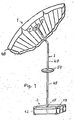
- a sun protection screen has a canopy designated overall by 1, a handle 2 and an umbrella stand designed as a carrying container 3.
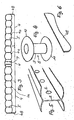
- the canopy consists, as can be seen in FIG. 3, of individual chambers 4 which, according to FIG. 5, are divided by webs 5 which have openings 6 for air balance within the chamber.
- the chambers 4 can be inflated independently of one another and each have a valve 4a for this purpose.
- An opening 7 is provided in the center of the protective roof 1, into which a screen hole reinforcement 8 according to FIG. 4 is inserted.
- This is constructed in accordance with a coil former and has a cylindrical part 9 which fits into the opening 7 and two flanges 10 and 11 which rest on the top and bottom of the canopy.
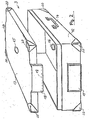
- the umbrella stand is designed as a case-like carrying container 3 as shown in FIG. 2 and has a lower part 12 and a lid 13.
- a handle 14 is provided on the lower part 12.
- the cover 13 has a central opening 15 provided for the passage of the stem 2.
- annular holder 16 for the stem end, aligned with the opening 15.
- a projection 17 is provided on the lower part 12, over which, in the closed state of the carrying case, an expression 18 engages, which can be latched with an inwardly projecting edge 19 under the projection 17 with prestress.
- Corner protectors 20 are provided at the corners of the lower part 12 and the cover 13.
- a lower pane 21 according to FIG. 9 and an upper pane 22 according to FIG. 10 are provided for fastening the protective roof 1 to the handle 2, which come into contact with the upper and lower side of the protective roof as shown in FIG hold on stick 2.
- the lower disc 21 has a central opening 23 which corresponds to the diameter of the stem 2 in the area 24, which is in the assembled state in the opening 7 of the screen.
- the disc 21 lies against a stop 25 which is attached to the handle 2.
- the section 24 of the stem 2 is received in the assembled state within the central body 9 of the hole reinforcement.
- the disks 21 and 22 rest on the flanges 10 and 11 of the hole reinforcement.
- the upper end 26 of the stem 2 protruding from the canopy has longitudinal grooves 27 into which teeth 28 engage project inward within opening 29 of upper disc 22 into opening 29.
- This engagement takes place only while the upper disk 22 is being pushed onto the upper handle end 26, the disk 22 being pushed downward until the teeth 28 projecting inwards into a transverse groove 30 which extends over the entire circumference transversely to the longitudinal axis of the handle Intervention.
- the disc is rotated so that the teeth 28 come to rest below the regions 31 remaining between the longitudinal grooves 27 of the stem end. In this way, the pane is secured against being pulled off and the canopy is clamped between these two panes 21 and 22.
- This construction enables the canopy and handle to be assembled without tools.
- the disks are provided with openings 32 and 33.
- FIGS. 11 and 12 A variant of the umbrella stand is shown in FIGS. 11 and 12.
- the case-like carrying container has a lower part 34 and a lid 35 fastened thereon, which is injection molded directly onto the lower part via a weak point when this plastic carrying container is produced, so that the lid can be moved relative to the lower part.
- an opening 36 is provided, which is used to insert the handle 2.
- This opening can be closed by a cover 37 which is fastened to a molded-on tab 38.
- a conical shape protrudes inwards Elevation 40 is provided with an opening 41 aligned with opening 36. The handle 2 can be inserted into the openings 36 and 41 and thus fixed in its vertical position.
- a retaining ring 2a can be pushed on and clamped on the stem in order to prevent the stem from being pulled out of the umbrella stand.
- the lower part 39 like the lower part 12 of the case-like carrying container according to FIG. 2, is filled with water, stones or with sand. So that the umbrella stand can be carried in the horizontal position, recessed handles 42 are molded in.
- a carrying handle 43 is used to carry the case-shaped carrying container 3.
- four short feet 44 are provided in the corners in order to prevent this container from slipping on level ground when the screen is exposed to wind.
- tabs 48 are attached to the edge of the canopy, which hang down and are shown on an enlarged scale in FIG. 6. These rags hang down over the canopy and cover the edge of the same, so that when the canopy is viewed from the side, the thickness of the inflatable chambers is not noticeable and the one pressure of a conventional sunshade is conveyed.
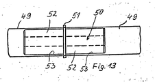
- the handle 2 is constructed from a plurality of sections 49 which are plugged together in accordance with FIG. 13.
- a bolt 50 is used, which has plug pins 52 on both sides of a collar 51, which can be inserted into corresponding socket-like recesses 53 of the sections 49.
- the sections 49 are made so long that they correspond at most to the inside diameter of the carrying case 3, so that they are accommodated in the carrying case 3 in the disassembled state together with the holding disks 21 and 22 and the canopy 1 which can be folded up after deflating the air can.
- a disc 54 can be clamped between two sections 49 of the stem 2 approximately halfway up the stem, which disc can serve as a storage disc for drinking cups, watches, jewelry, etc. in the position shown in FIG. 1. When released from the stick, this disc can be used as a throwing disc for games on the beach.
Landscapes
- Holders For Apparel And Elements Relating To Apparel (AREA)
Priority Applications (1)
| Application Number | Priority Date | Filing Date | Title |
|---|---|---|---|
| EP87112666A EP0306542A1 (fr) | 1987-08-31 | 1987-08-31 | Parasol |
Applications Claiming Priority (1)
| Application Number | Priority Date | Filing Date | Title |
|---|---|---|---|
| EP87112666A EP0306542A1 (fr) | 1987-08-31 | 1987-08-31 | Parasol |
Publications (1)
| Publication Number | Publication Date |
|---|---|
| EP0306542A1 true EP0306542A1 (fr) | 1989-03-15 |
Family
ID=8197237
Family Applications (1)
| Application Number | Title | Priority Date | Filing Date |
|---|---|---|---|
| EP87112666A Withdrawn EP0306542A1 (fr) | 1987-08-31 | 1987-08-31 | Parasol |
Country Status (1)
| Country | Link |
|---|---|
| EP (1) | EP0306542A1 (fr) |
Cited By (7)
| Publication number | Priority date | Publication date | Assignee | Title |
|---|---|---|---|---|
| EP0443615A3 (en) * | 1990-02-23 | 1992-01-15 | Kornelia Baur | Sunshade |
| WO1994004060A1 (fr) * | 1992-08-20 | 1994-03-03 | Shadow Products Ltd. | Parasol reglable destine a un recipient pour boisson |
| RU2126221C1 (ru) * | 1997-03-20 | 1999-02-20 | Бехер Текстиль-Унд Штальбау ГмбХ | Зонт, в частности, стационарный зонт |
| GB2372700A (en) * | 2001-03-02 | 2002-09-04 | Fulton Company Ltd A | Collapsible shelter supported by its case |
| GB2472647A (en) * | 2009-08-14 | 2011-02-16 | Richard Atkinson | Portable stand with carrying case |
| US10925360B1 (en) * | 2019-10-18 | 2021-02-23 | Mike Schwiebert | Portable, ergonomic, and selectively adjustable umbrella and seat support structure |
| US11408192B2 (en) * | 2019-10-18 | 2022-08-09 | Mike Schwiebert | Portable, ergonomic, and selectively adjustable umbrella and seat support structure |
Citations (8)
| Publication number | Priority date | Publication date | Assignee | Title |
|---|---|---|---|---|
| US2049380A (en) * | 1936-03-02 | 1936-07-28 | Huber Charlotte | Inflatable umbrella |
| US3683947A (en) * | 1970-03-27 | 1972-08-15 | Armand A Muller | Umbrella construction |
| US3935874A (en) * | 1974-12-18 | 1976-02-03 | Helen Cohen | Umbrella assembly |
| FR2394654A1 (fr) * | 1977-06-17 | 1979-01-12 | Zimm Zamm Ag | Support pour objets tubulaires tels que parasols pour la plage |
| US4296693A (en) * | 1979-02-08 | 1981-10-27 | Archer Richard W | Beach umbrella support |
| US4471933A (en) * | 1981-08-21 | 1984-09-18 | Nelson Donald R | Music stand |
| US4562849A (en) * | 1983-12-23 | 1986-01-07 | Vladimir Sirota | Umbrella unit, and car and the like provided therewith |
| DE8703822U1 (de) * | 1986-06-10 | 1987-10-08 | Babl, Arthur, 8044 Unterschleißheim | Sonnenschutzschirm |
-
1987
- 1987-08-31 EP EP87112666A patent/EP0306542A1/fr not_active Withdrawn
Patent Citations (8)
| Publication number | Priority date | Publication date | Assignee | Title |
|---|---|---|---|---|
| US2049380A (en) * | 1936-03-02 | 1936-07-28 | Huber Charlotte | Inflatable umbrella |
| US3683947A (en) * | 1970-03-27 | 1972-08-15 | Armand A Muller | Umbrella construction |
| US3935874A (en) * | 1974-12-18 | 1976-02-03 | Helen Cohen | Umbrella assembly |
| FR2394654A1 (fr) * | 1977-06-17 | 1979-01-12 | Zimm Zamm Ag | Support pour objets tubulaires tels que parasols pour la plage |
| US4296693A (en) * | 1979-02-08 | 1981-10-27 | Archer Richard W | Beach umbrella support |
| US4471933A (en) * | 1981-08-21 | 1984-09-18 | Nelson Donald R | Music stand |
| US4562849A (en) * | 1983-12-23 | 1986-01-07 | Vladimir Sirota | Umbrella unit, and car and the like provided therewith |
| DE8703822U1 (de) * | 1986-06-10 | 1987-10-08 | Babl, Arthur, 8044 Unterschleißheim | Sonnenschutzschirm |
Cited By (9)
| Publication number | Priority date | Publication date | Assignee | Title |
|---|---|---|---|---|
| EP0443615A3 (en) * | 1990-02-23 | 1992-01-15 | Kornelia Baur | Sunshade |
| WO1994004060A1 (fr) * | 1992-08-20 | 1994-03-03 | Shadow Products Ltd. | Parasol reglable destine a un recipient pour boisson |
| RU2126221C1 (ru) * | 1997-03-20 | 1999-02-20 | Бехер Текстиль-Унд Штальбау ГмбХ | Зонт, в частности, стационарный зонт |
| GB2372700A (en) * | 2001-03-02 | 2002-09-04 | Fulton Company Ltd A | Collapsible shelter supported by its case |
| GB2372700B (en) * | 2001-03-02 | 2003-01-22 | Fulton Company Ltd A | Improvements in collapsible shelters |
| GB2472647A (en) * | 2009-08-14 | 2011-02-16 | Richard Atkinson | Portable stand with carrying case |
| GB2472647B (en) * | 2009-08-14 | 2014-02-26 | Richard Atkinson | A portable music stand |
| US10925360B1 (en) * | 2019-10-18 | 2021-02-23 | Mike Schwiebert | Portable, ergonomic, and selectively adjustable umbrella and seat support structure |
| US11408192B2 (en) * | 2019-10-18 | 2022-08-09 | Mike Schwiebert | Portable, ergonomic, and selectively adjustable umbrella and seat support structure |
Similar Documents
| Publication | Publication Date | Title |
|---|---|---|
| DE69428190T2 (de) | Selbstaufrichtende tragbare textile struktur | |
| DE102007012223A1 (de) | Mastständer | |
| EP0432576A2 (fr) | Parasol | |
| DE29713966U1 (de) | Schirmförmiges Faltzelt mit Doppelschicht | |
| DE2239114B2 (de) | Zelt | |
| AT392316B (de) | Verbindungsstueck zur aufnahme der enden von stabteilen eines kuppelzeltes | |
| EP0306542A1 (fr) | Parasol | |
| EP1731056B1 (fr) | Parasol comprenant un dispositif de tension de couverture placé sur un mât | |
| DE69925974T2 (de) | Bauteil zum herstellen einer wand | |
| DE29906116U1 (de) | Standschirm | |
| DE202018000481U1 (de) | Ein abbaubarer Schirmsitz | |
| EP3438393B1 (fr) | Dispositif de conservation d'objets | |
| EP1426265B1 (fr) | Emballage avec dispositif de transport pour tente pliée | |
| EP3226722B1 (fr) | Table d'appoint pour parasol | |
| DE29719904U1 (de) | Schirmfuß | |
| DE8221385U1 (de) | Sockel fuer einen aufstellbaren, z.b. als garten- oder strandschirm verwendbaren sonnenschirm | |
| EP0699261B1 (fr) | Toile de protection contre le soleil | |
| WO2006094418A1 (fr) | Support de parasol | |
| DE20311074U1 (de) | Vorrichtung zum Schützen von Pflanzen | |
| DE29815082U1 (de) | Abdeckung | |
| DE19635030A1 (de) | Schirmvorrichtung | |
| DE531638C (de) | In eine Stockform zusammenlegbarer Stuhl | |
| DE20215513U1 (de) | Wind- und Sonnenschutzschirm zur Aufnahme von Personen | |
| DE7319036U (de) | Sonnenschirm | |
| DE102022132361A1 (de) | Haltevorrichtung für eine Batterieanordnung einer Lichterkette |
Legal Events
| Date | Code | Title | Description |
|---|---|---|---|
| PUAI | Public reference made under article 153(3) epc to a published international application that has entered the european phase |
Free format text: ORIGINAL CODE: 0009012 |
|
| AK | Designated contracting states |
Kind code of ref document: A1 Designated state(s): AT BE CH DE ES FR GB GR IT LI LU NL SE |
|
| RBV | Designated contracting states (corrected) |
Designated state(s): AT BE CH DE ES FR GR IT LI NL |
|
| STAA | Information on the status of an ep patent application or granted ep patent |
Free format text: STATUS: THE APPLICATION IS DEEMED TO BE WITHDRAWN |
|
| 18D | Application deemed to be withdrawn |
Effective date: 19890916 |