EP0306565A1 - Rasterpunkt-Korrektionsverfahren - Google Patents
Rasterpunkt-Korrektionsverfahren Download PDFInfo
- Publication number
- EP0306565A1 EP0306565A1 EP87201742A EP87201742A EP0306565A1 EP 0306565 A1 EP0306565 A1 EP 0306565A1 EP 87201742 A EP87201742 A EP 87201742A EP 87201742 A EP87201742 A EP 87201742A EP 0306565 A1 EP0306565 A1 EP 0306565A1
- Authority
- EP
- European Patent Office
- Prior art keywords
- areas
- dot size
- exposure
- process according
- separation
- Prior art date
- Legal status (The legal status is an assumption and is not a legal conclusion. Google has not performed a legal analysis and makes no representation as to the accuracy of the status listed.)
- Withdrawn
Links
- 238000000034 method Methods 0.000 title claims abstract description 48
- 238000012937 correction Methods 0.000 title claims abstract description 36
- 230000008569 process Effects 0.000 title claims description 32
- 238000000926 separation method Methods 0.000 claims abstract description 74
- 238000012986 modification Methods 0.000 claims abstract description 20
- 230000004048 modification Effects 0.000 claims abstract description 20
- 230000003287 optical effect Effects 0.000 claims abstract description 16
- 239000000463 material Substances 0.000 claims description 33
- 230000008859 change Effects 0.000 claims description 19
- 230000007423 decrease Effects 0.000 claims description 18
- 230000000873 masking effect Effects 0.000 claims description 14
- 238000002955 isolation Methods 0.000 claims description 13
- 230000000694 effects Effects 0.000 claims description 12
- 229910052709 silver Inorganic materials 0.000 claims description 12
- 239000004332 silver Substances 0.000 claims description 12
- -1 silver halide Chemical class 0.000 claims description 12
- 239000000839 emulsion Substances 0.000 claims description 11
- 230000033458 reproduction Effects 0.000 claims description 7
- 238000011161 development Methods 0.000 claims description 6
- 238000012545 processing Methods 0.000 claims description 4
- 238000003860 storage Methods 0.000 claims description 4
- 230000001747 exhibiting effect Effects 0.000 claims description 3
- 238000004040 coloring Methods 0.000 claims description 2
- 230000003247 decreasing effect Effects 0.000 claims description 2
- 238000004519 manufacturing process Methods 0.000 abstract description 9
- 238000002360 preparation method Methods 0.000 abstract description 3
- 238000009826 distribution Methods 0.000 description 4
- 239000000976 ink Substances 0.000 description 4
- 238000011160 research Methods 0.000 description 4
- 238000005520 cutting process Methods 0.000 description 3
- 238000005549 size reduction Methods 0.000 description 3
- 230000003595 spectral effect Effects 0.000 description 3
- 238000001312 dry etching Methods 0.000 description 2
- 230000002093 peripheral effect Effects 0.000 description 2
- 230000000007 visual effect Effects 0.000 description 2
- 206010070834 Sensitisation Diseases 0.000 description 1
- 238000010521 absorption reaction Methods 0.000 description 1
- 230000004075 alteration Effects 0.000 description 1
- 230000008901 benefit Effects 0.000 description 1
- 239000003086 colorant Substances 0.000 description 1
- 239000002131 composite material Substances 0.000 description 1
- 238000001514 detection method Methods 0.000 description 1
- 238000010586 diagram Methods 0.000 description 1
- 238000005530 etching Methods 0.000 description 1
- 238000000424 optical density measurement Methods 0.000 description 1
- 230000009467 reduction Effects 0.000 description 1
- 230000035945 sensitivity Effects 0.000 description 1
- 230000008313 sensitization Effects 0.000 description 1
Images

Classifications
-
- G—PHYSICS
- G03—PHOTOGRAPHY; CINEMATOGRAPHY; ANALOGOUS TECHNIQUES USING WAVES OTHER THAN OPTICAL WAVES; ELECTROGRAPHY; HOLOGRAPHY
- G03F—PHOTOMECHANICAL PRODUCTION OF TEXTURED OR PATTERNED SURFACES, e.g. FOR PRINTING, FOR PROCESSING OF SEMICONDUCTOR DEVICES; MATERIALS THEREFOR; ORIGINALS THEREFOR; APPARATUS SPECIALLY ADAPTED THEREFOR
- G03F5/00—Screening processes; Screens therefor
-
- G—PHYSICS
- G03—PHOTOGRAPHY; CINEMATOGRAPHY; ANALOGOUS TECHNIQUES USING WAVES OTHER THAN OPTICAL WAVES; ELECTROGRAPHY; HOLOGRAPHY
- G03F—PHOTOMECHANICAL PRODUCTION OF TEXTURED OR PATTERNED SURFACES, e.g. FOR PRINTING, FOR PROCESSING OF SEMICONDUCTOR DEVICES; MATERIALS THEREFOR; ORIGINALS THEREFOR; APPARATUS SPECIALLY ADAPTED THEREFOR
- G03F3/00—Colour separation; Correction of tonal value
- G03F3/04—Colour separation; Correction of tonal value by photographic means
- G03F3/06—Colour separation; Correction of tonal value by photographic means by masking
-
- G—PHYSICS
- G03—PHOTOGRAPHY; CINEMATOGRAPHY; ANALOGOUS TECHNIQUES USING WAVES OTHER THAN OPTICAL WAVES; ELECTROGRAPHY; HOLOGRAPHY
- G03F—PHOTOMECHANICAL PRODUCTION OF TEXTURED OR PATTERNED SURFACES, e.g. FOR PRINTING, FOR PROCESSING OF SEMICONDUCTOR DEVICES; MATERIALS THEREFOR; ORIGINALS THEREFOR; APPARATUS SPECIALLY ADAPTED THEREFOR
- G03F3/00—Colour separation; Correction of tonal value
- G03F3/10—Checking the colour or tonal value of separation negatives or positives
- G03F3/101—Colour or tonal value checking by non-photographic means or by means other than using non-impact printing methods or duplicating or marking methods covered by B41M5/00
Definitions
- the present invention relates to dot-size correction or modification in halftone images, and more particularly concerns the use of said correction in a process for producing colour-corrected or colour-modified colour separation records for used in the production of printing plates for printing reproductions of coloured originals, in particular of colour photographs or art-work.
- inks of the subtractive colours cyan, magenta and yellow are used, as well as a certain amount of black applied by the black printer. Because of the overlapping spectral absorption bands of the subtractively coloured inks, the use of printing plates produced from photographic colour separation halftones without any correction usually results in poor quality colour reproduction. Colour reproduction normally involves corrections for hue, saturation and lightness values. Apart from colour corrections necessary for faithful colour reproduction, colour modifications are often necessary for special effects, for example for purely aesthetic reasons or in order to achieve a heightened visual impact of selected matter in printed advertisements.
- the correction of halftone images is therefore particularly important with regard to the correction of black-and-white colour separation prints serving as photomasks in the production of printing plates for printing with subtractive colour printing inks.
- one or more isolation masks is or are made for use in combination with one or more of the initial halftone separations when making the aforesaid contact prints.
- An isolation mask protects the light-sensitive print material from the excess exposure dose except in the area where the dot size change is required. The over-exposure results in an increase of dot size.
- a suitable mask can be produced from a so-called cut-and-peel film or by hand-lacquering a mask film (see e.g. DE-P 3 140 955).
- FIG. 1 A simple example of the preparation of a colour-corrected or modified colour separation according to the above described prior art procedure is schematically illustrated in Fig. 1 of the accompanying drawings.
- P1 represents a positive halftone separation as produced by exposure of light-sensitive film to red, blue or green light transmitted through or from the artwork or other original to be printed, via a red, blue or green filter.
- the halftone separations are produced on a laser scanner recorder by a procedure known to those skilled in the art.
- the percentage change in dot size which is required in each area in order to effect the required colour change in that area is determined from optical density measurements in that area of the initial halftone separations and by reference to charts, or in the case of computer assisted processing it can be determined by an appropriately programmed data processor fed with the relevant data.
- a negative working silver halide emulsion film N1 is exposed through the halftone separation P1.
- the film N1 is subjected to contact exposure through P1 and mask M1 and through P1 and mask M2 respectively. Because N1 is a negative working film the additional exposure doses in the areas 1 and 2 as defined by the masks M1 and M2 have the effect of increasing the sizes of the dots in the those areas of the latent image in the film.
- the exposure dose is controlled so that it results in the required predetermined percentage dot size change in the area 1 or 2 as the case may be, of the negative film.
- the film N2 After development of the exposed film N1 it is used in a contact exposure step represented by arrow 7 for forming a corresponding positive latent image in a second negative working silver halide emulsion film N2 so that the dots of this positive image exhibit the required decrease in dot sizes in the areas 1 and 2.
- the film N2 is subjected to contact exposure through N1 and mask M3 and through N1 and M4 respectively.
- the additional exposure doses in the areas 3 and 4 as defined by the masks M3 and M4 has the effect of increasing the sizes of the dots in those areas of the latent image in the film.
- the exposure dose is controlled so that it results in the required predetermined percentage dot size change in the area 3 or 4 as the case may be.
- the film N2 After development of the film N2 it is ready for use as a colour-modified halftone separation in the preparation of a printing plate.
- the colour-modified halftone separation could be made by directly exposing a positive-working silver halide emulsion film to the initial halftone separation P1 without a mask and also to such separation masked by each of the masks M1 and M2 in turn.
- a process for producing halftone images being corrected or modified in dot-size in certain areas and suited for use in making a printing plate for printing reproductions of an image from an initial photographic halftone colour separation which in a plurality of areas has dot sizes which are either smaller or larger than those which the printing plate should have in those areas for achieving a required colouring effect;
- which process comprises the steps of determining the percentage dot size increase or decrease required in each of said areas, and exposing and processing light-sensitive material (called print material) thereby to produce by mask controlled over-exposure a print exhibiting the required dot size changes in said areas; characterized in that (1) said light-sensitive print material is exposed through an assembly of said initial separation and a masking means comprising a photographic film element having in its areas coinciding with the said areas of the initial separation in which dot size decrease or increase is required, optical densities such that the required dot size changes in said areas can be produced in said print material (while no dot size change occurs in the remaining areas requiring no do
- said photographic film element is interposed between said initial separation and said print material or said initial separation is interposed between said photographic film element and said print material.
- the invention enables through the use of single-element exposure masks combined with a common exposure dose to obtain colour-corrected or modified halftone colour separations with fewer copying exposure steps than are necessary according to the prior art practice.
- the reduction in the number of steps, each of which requires registration of materials in a printing frame, can be considerable, depending on the number of different areas of a halftone separation image in which correction or modification is required. It is not uncommon for corrections or modifications to be required in eight or more different areas.
- Another important advantage of the invention is that it is neither necessary to alter the over-exposure dosage to effect different percentage dot size increases or decreases as the case may be in different areas nor to have an initial or final non-masked exposure step.
- said masking means called hereinafter correction mask, is produced by the steps :
- said masking means assembled with the initial separation is used in said common exposure in combination with a negative working silver halide emulsion print material, which on development provides a halftone separation containing areas having increased dot size with respect to said initial halftone separation.
- said halftone separation containing areas having increased dot size is copied for image reversal on another negative working silver halide emulsion print material to obtain therewith a halftone separation containing areas having decreased dot size with respect to said initial halftone separation.
- the photographic material used for the production of said correction masks is preferably a material suited for continuous tone reproduction having a large exposure latitude, i.e. fairly soft gradation.
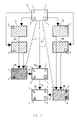
- FIG. 2 A simple example of a process according to the invention, selected for easy comparison with Fig. 1, is schematically represented in Fig. 2 of the accompanying drawings.
- elements which are substantially identical with elements represented in Fig. 1 are denoted by the same reference indicia as in that figure.
- FIG. 2 is a halftone separation image corresponding with P1 in Fig. 1; the triangles 1,2 denote areas in which a dot size reduction is required and the squares 3,4 denote areas in which a dot size increase is required.
- Isolation masks M1, M2, M3 and M4 are prepared, each of which, like the correspondingly denoted mask in Fig. 1, has an area of negligible optical density corresponding with one of the areas 1-4 but is otherwise effectively opaque.
- the masks M1-M4 are used for a different purpose. Instead of being interposed one by one between the initial halftone separation P1 and film N1 or film N2 as the case may be preparatory to an over-exposure step, the masks are used for producing composite photographic correction masks M5 and M6.
- the mask M5 is a dot size increase mask prepared by successively exposing a light-sensitive positive-working film to masks M1 and M2 after an initial non-masked (overall) exposure has been given and developing the latent images so that the areas 1, 2 and the background areas thereof have different predetermined optical densities.
- the background density obtained by said overall exposure is the highest density, whereas the densities in the areas corresponding with the areas to be dot size corrected have an appropriate lower value to obtain the desired degree of overexposure for dot size increase.
- the density in each of those areas is such that the common exposure dose emitted during the later masked printing step will be so modulated by said areas of the mask that the over-exposure dose reaching the film N1 will bring about the required percentage dot size increase in each of said areas.
- the mask M5 has a density such that it produces no correction or modification of the initial halftone separation when used in the masked printing step.
- the mask M6 is a dot size increase mask prepared in a similar manner, from masks M3 and M4.
- optical densities of areas 3 an 4 of mask M6 are such that the light doses reaching areas 3 and 4 of the film N2 during the masked exposure of that film will effect the required dot size increases in those areas. While the density of the remaining areas is such that it produces no correction or modification of the initial halftone separation in these areas.
- the negative-working film N1 is exposed in a single step while the mask M5 is in position between the separation P1 and the film N1. This single exposure step is represented by arrows 6 and 6 ⁇ . After development of the film N1 it is contact printed in a single exposure step as represented by arrows 8 and 8 ⁇ onto negative-working film N2 while the mask M6 is in position between the two films N1 and N2.
- each of the films N1 and N2 is subjected to only one masked exposure and that even if there were several more areas in which dot size decreases or increases were required it would still suffice to use a single dot size decrease mask and a single dot size increase mask and to use each such mask in a single masked exposure of the film N1 or N2 as the case may be. If there are more areas requiring a dot size decrease or increase than can reasonably be corrected by a single mask then of course an extra dot size decrease mask or an extra dot size increase mask as the case may be can be prepared for correcting the extra areas.
- the halftone separation P1 could be printed in masked state directly onto a positive-working film, instead of using the combination of the two negative working films N1 and N2.
- the masks M1-M4 can be prepared photographically.
- the mask areas 1-4 should be free from any dot pattern and in exposing photographic film for producing any of the masks, a transparent interlay film can be used between the mask film and the halftone separation and a matt layer on top of the halftone separation to achieve a diffuse exposure.
- the masks M1-M4 can be produced by a plotting and cutting method.
- each of the photographic masks M5 and M6 is produced with the aid of a digital isolation mask stored as a digital data file in a computer (not shown).
- Each file of digital data is used to control the exposure of a light-sensitive element by means of a writing laser scanner and that element is then developed to form the photographic mask M5 or M6.
- room-light film which can be handled in normal room light without fogging but is still sensitive enough for exposure in a contact-exposure camera with the usual light-sources.
- room-light film examples are described in Research Disclosure, March 1978, item 16,735 and in US-P 2,219,667. Due to the absence of spectral sensitization those materials can be handled in bright yellow light without fogging.
- the photographic masks are produced on a laser recorder scanner using films that have the appropriate spectral sensitivity for the applied laser beam.
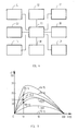
- Fig. 3 of the accompanying drawings is an example of a set of such gauge-curves which are drawn by plotting dot size increases ⁇ P (%) against initial dot size P (%).
- the different curves F0-F4 relate to different over-exposure doses, expressed as relative log Exposure factors F.
- the over-exposure dose or relative exposure factor required for that purpose in unmasked state can be represented by a point P.
- an exposure factor curve F can then be drawn through point P to represent the effect of that exposure factor on dots of various initial sizes.
- E 1.5x10 ⁇ 3 W/m2
- K 1.5
- t 10 s
- the density D being the mask density is set to be equal to zero.
- D min 0.2 the exposure factor F becomes at least 5.46 for a W max of 87x10 ⁇ 3 J/m2.
- a densitometer can be used for measuring the integral density of representative spots in any given area of the halftone separations and density readings can be translated into percent dot values.
- the process can be partly or almost entirely automated using a micro-processor or computer.
- the information pertaining to appropriate over-exposure doses as represented by the gauge curves of Fig. 3, or by a nomograph, can be written in the form of a software program and fed to a computer which determines from that data and other input data the appropriate over-exposure dose for particular applications of the process, expressed as an exposure factor calibrated with respect to the exposure apparatus and the light-sensitive material to be used.
- the exposure apparatus itself can incorporate a micro-processor chip which serves for direct exposure control in an electronic processing based on a software program as above referred to.
- the apparatus may comprise a densitometer, an operator console comprising a graphic video monitor screen provided with a mouse driven monitor cursor, a computer linked to a high capacity storage device and a computer controlled contact frame exposure device.
- the apparatus can also comprise a digitizer tablet and a graphic mask plotter or mask cutter device.
- An apparatus including a said digitizer tablet and graphic mask plotter or mask cutting device can operate in conjunction with a scanning-reading device and a writing laser exposure device.
- Fig. 4 of the accompanying drawings is a block diagram of an example of an apparatus assembly designed for use in carrying a process according to the invention.
- the apparatus assembly contains the following operative parts: - a densitometer 11 under the light detection head of which the halftone separation can be moved manually for measuring the densities of elementary surface areas, called elementary spots, which densities identify the % dot values of such spots; - an operator console 12 comprising a graphic video monitor provided with a mouse driven monitor cursor, allowing the computer assisted creation and display of correction masks; - a digitizer 13 which provides digital values for the spatial definition of area contours obtained as relative point coordinates in appropriate elementary distance units, - a reading scan device 14 which allows the scanning of a separation image on a point by point or line by line base and generates signals representing the densities or % dot values of elementary spots; - a computer 15 with interfacing circuits to the peripheral devices 11, 12, 13, 14, 16, 17, 18 and 19. - a high capacity digital storage means 16, - a computer controlled contact frame exposure device 17, - a computer controlled graphic plotter or cutter device 18, - a computer controlled scanning exposure device 19, e.g. a writing
- the apparatus may comprise a densitometer 11, an operator console 12, a computer 15, a digital storage means 16 and a computer controlled contact frame exposure device 17.
- the process can for example proceed as follows: The operator starts by entering the mode of operation defining the peripherals that will be used to carry out the halftone correction.
- the areas to be corrected and the amount of correction needed are specified.
- the areas to be corrected are defined by their densities, corresponding with particular % dot values, or by contour coordinates of the initial separation.
- a mouse driven monitor cursor can be used whereby the contours of the areas on which correction is required are displayed on a monitor screen.
- the data defining said areas are entered into the computer as digitized readings which may be derived from a density reading device, a digitizer tablet or a scan device.
- the corrections required are determined and entered by keyboard or by mouse driven menu into the computer as a desired dot size change in the defined areas.
- Separate area isolation masks when required, can be produced by a photographic technique or plotting and cutting technique (or a combination of said techniques for the different area isolation masks), and used one by one with an appropriate computer controlled exposure dose for producing one or more photographic correction masks in photographic silver halide emulsion material as hereinbefore described.
- digital isolation masks can be used.
- digital isolation masks is meant that the data representing the areas to be isolated are stored and processed to form files of digital data which constitute such masks.
- Such digital masks can directly effect exposure control of a writing laser scanner, the mask data serving to modulate the radiant energy density of the scanning laser beam for exposing a positive or negative working silver halide film which then on development forms a single dot-size increase mask or a single dot-size decrease mask.
- the dot size increases and/or decreases which will result from the use of the prepared masks can then be checked for correctness by measuring the densities of some control points in the masks.
Landscapes
- Physics & Mathematics (AREA)
- General Physics & Mathematics (AREA)
- Silver Salt Photography Or Processing Solution Therefor (AREA)
Priority Applications (1)
| Application Number | Priority Date | Filing Date | Title |
|---|---|---|---|
| EP87201742A EP0306565A1 (de) | 1987-09-11 | 1987-09-11 | Rasterpunkt-Korrektionsverfahren |
Applications Claiming Priority (1)
| Application Number | Priority Date | Filing Date | Title |
|---|---|---|---|
| EP87201742A EP0306565A1 (de) | 1987-09-11 | 1987-09-11 | Rasterpunkt-Korrektionsverfahren |
Publications (1)
| Publication Number | Publication Date |
|---|---|
| EP0306565A1 true EP0306565A1 (de) | 1989-03-15 |
Family
ID=8197671
Family Applications (1)
| Application Number | Title | Priority Date | Filing Date |
|---|---|---|---|
| EP87201742A Withdrawn EP0306565A1 (de) | 1987-09-11 | 1987-09-11 | Rasterpunkt-Korrektionsverfahren |
Country Status (1)
| Country | Link |
|---|---|
| EP (1) | EP0306565A1 (de) |
Citations (1)
| Publication number | Priority date | Publication date | Assignee | Title |
|---|---|---|---|---|
| DE3614684C1 (de) * | 1986-04-30 | 1987-06-11 | Du Pont Deutschland | Photographische Masken fuer die Tonwertkorrektur |
-
1987
- 1987-09-11 EP EP87201742A patent/EP0306565A1/de not_active Withdrawn
Patent Citations (1)
| Publication number | Priority date | Publication date | Assignee | Title |
|---|---|---|---|---|
| DE3614684C1 (de) * | 1986-04-30 | 1987-06-11 | Du Pont Deutschland | Photographische Masken fuer die Tonwertkorrektur |
Similar Documents
| Publication | Publication Date | Title |
|---|---|---|
| US5563717A (en) | Method and means for calibration of photographic media using pre-exposed miniature images | |
| EP0242184B1 (de) | Bilderzeugungssystem | |
| US4081828A (en) | Method for halftone reproduction of continuous tone images | |
| US4553835A (en) | Process for producing pre-press color proofs | |
| US4504141A (en) | System for making matched backgrounds | |
| US5010398A (en) | Method for colour correction by dry dot etching using photographically produced mask | |
| GB2301253A (en) | Tonal control of halftone colour image | |
| US3913477A (en) | Photogravure process for preparing a gravure press for multicolor printing | |
| US4997733A (en) | Process for the production of photographic masks | |
| EP0306565A1 (de) | Rasterpunkt-Korrektionsverfahren | |
| US5462841A (en) | Tone rendition of halfstone images by projection exposure | |
| JPH10155091A (ja) | 画像記録装置 | |
| US2176518A (en) | Photomechanical color process | |
| US1818080A (en) | ||
| US4774165A (en) | Method for direct making of lithographic printing plates | |
| EP0209105A2 (de) | Methoden der Änderung der optischen Dichte für den einfachen Farbprobedruck und Maske dafür | |
| EP0219560B1 (de) | Verfahren zur Herstellung von Farbprüffolien | |
| JP3143709B2 (ja) | スキャナ読込み補正方法 | |
| CA1258195A (en) | Process for producing pre-press color proofs | |
| US2405739A (en) | Photographic tone correction mask | |
| JPH0513487B2 (de) | ||
| JPH051448B2 (de) | ||
| JP2627742B2 (ja) | 校正用文字台紙の修整方法および修整用印画紙 | |
| JPH0677153B2 (ja) | 多色カラ−ダイレクト製版法 | |
| JPS635333A (ja) | カラ−画像の解析条件設定方法 |
Legal Events
| Date | Code | Title | Description |
|---|---|---|---|
| PUAI | Public reference made under article 153(3) epc to a published international application that has entered the european phase |
Free format text: ORIGINAL CODE: 0009012 |
|
| AK | Designated contracting states |
Kind code of ref document: A1 Designated state(s): AT BE CH DE ES FR GB GR IT LI LU NL SE |
|
| RBV | Designated contracting states (corrected) |
Designated state(s): BE |
|
| REG | Reference to a national code |
Ref country code: DE Ref legal event code: 8566 |
|
| STAA | Information on the status of an ep patent application or granted ep patent |
Free format text: STATUS: THE APPLICATION IS DEEMED TO BE WITHDRAWN |
|
| 18D | Application deemed to be withdrawn |
Effective date: 19890916 |