EP0306737A2 - Dispositif de traction hydraulique - Google Patents
Dispositif de traction hydraulique Download PDFInfo
- Publication number
- EP0306737A2 EP0306737A2 EP88113294A EP88113294A EP0306737A2 EP 0306737 A2 EP0306737 A2 EP 0306737A2 EP 88113294 A EP88113294 A EP 88113294A EP 88113294 A EP88113294 A EP 88113294A EP 0306737 A2 EP0306737 A2 EP 0306737A2
- Authority
- EP
- European Patent Office
- Prior art keywords
- pressure
- working cylinder
- cylinder
- working
- end wall
- Prior art date
- Legal status (The legal status is an assumption and is not a legal conclusion. Google has not performed a legal analysis and makes no representation as to the accuracy of the status listed.)
- Withdrawn
Links
Images
Classifications
-
- F—MECHANICAL ENGINEERING; LIGHTING; HEATING; WEAPONS; BLASTING
- F15—FLUID-PRESSURE ACTUATORS; HYDRAULICS OR PNEUMATICS IN GENERAL
- F15B—SYSTEMS ACTING BY MEANS OF FLUIDS IN GENERAL; FLUID-PRESSURE ACTUATORS, e.g. SERVOMOTORS; DETAILS OF FLUID-PRESSURE SYSTEMS, NOT OTHERWISE PROVIDED FOR
- F15B7/00—Systems in which the movement produced is definitely related to the output of a volumetric pump; Telemotors
-
- B—PERFORMING OPERATIONS; TRANSPORTING
- B25—HAND TOOLS; PORTABLE POWER-DRIVEN TOOLS; MANIPULATORS
- B25B—TOOLS OR BENCH DEVICES NOT OTHERWISE PROVIDED FOR, FOR FASTENING, CONNECTING, DISENGAGING, OR HOLDING
- B25B27/00—Hand tools, specially adapted for fitting together or separating parts or objects whether or not involving some deformation, not otherwise provided for
- B25B27/02—Hand tools, specially adapted for fitting together or separating parts or objects whether or not involving some deformation, not otherwise provided for for connecting objects by press fit or detaching same
- B25B27/026—Hand tools, specially adapted for fitting together or separating parts or objects whether or not involving some deformation, not otherwise provided for for connecting objects by press fit or detaching same fluid driven
-
- B—PERFORMING OPERATIONS; TRANSPORTING
- B25—HAND TOOLS; PORTABLE POWER-DRIVEN TOOLS; MANIPULATORS
- B25B—TOOLS OR BENCH DEVICES NOT OTHERWISE PROVIDED FOR, FOR FASTENING, CONNECTING, DISENGAGING, OR HOLDING
- B25B27/00—Hand tools, specially adapted for fitting together or separating parts or objects whether or not involving some deformation, not otherwise provided for
- B25B27/02—Hand tools, specially adapted for fitting together or separating parts or objects whether or not involving some deformation, not otherwise provided for for connecting objects by press fit or detaching same
- B25B27/06—Hand tools, specially adapted for fitting together or separating parts or objects whether or not involving some deformation, not otherwise provided for for connecting objects by press fit or detaching same inserting or withdrawing sleeves or bearing races
- B25B27/064—Hand tools, specially adapted for fitting together or separating parts or objects whether or not involving some deformation, not otherwise provided for for connecting objects by press fit or detaching same inserting or withdrawing sleeves or bearing races fluid driven
Definitions
- the invention relates to a hydraulic pulling device for removing and pressing in bearings or sleeves, in particular for axle bearings (roller bearings) of motor vehicles, consisting of a working cylinder with a working piston and a piston rod projecting through the end wall of the working cylinder, and of a smaller-diameter pressure cylinder, which with is connected to the working cylinder and in which a pressure piston actuated by a threaded spindle is arranged, which presses a hydraulic pressure medium into the larger diameter cylinder during its pressure movement.
- the working cylinder and the pressure cylinder are in a coaxial arrangement in the form of cylindrical axial bores of different diameters in a common cylindrical body housed, which is provided at one end with an external thread and at the other end with a key profile.
- the working chamber of the working cylinder in which the working piston is located has a diameter that is about 2.5 times larger than the pressure chamber of the pressure cylinder and is openly worked into the cylindrical body from the end face provided with the external thread.
- a guide tube provided over its entire length with an external thread can be fastened in the end, in which a pressure tappet, which is detachably connected to the working piston by a threaded pin, is guided.
- a threaded spindle is screwed into the cylindrical body from the opposite end, which acts on a pressure piston which is axially movably guided in order to convey a pressure medium from the pressure cylinder into the larger diameter working cylinder.
- This known device is used in such a way that on the guide tube provided with an external thread, in which the pressure tappet is guided, a support device consisting of a cross bar and gripper fingers with barbs is screwed on and hung, for example, on a gearwheel or a pulley to be removed from a shaft journal , so that the lower end of the pressure plunger sits on the end face of the shaft to be pressed out of the gear.
- a support device consisting of a cross bar and gripper fingers with barbs is screwed on and hung, for example, on a gearwheel or a pulley to be removed from a shaft journal , so that the lower end of the pressure plunger sits on the end face of the shaft to be pressed out of the gear.
- Hydraulic systems are also already known in which the clamping force introduced manually by means of a screw can be redirected or distributed simultaneously or differently to different clamping parts by means of plastic mass or oil.
- the preferred area of application for such hydraulic systems is multi-piece clamping by hand. Instead of mechanical clamping force transmission, the greater the number of workpieces to be clamped, the more possible.
- only small clamping strokes are provided in these known systems. For larger clamping strokes they are not suitable because there is only one rotary screw with a relatively small pressure stroke.
- the invention has for its object to provide a hydraulic pulling device of the type mentioned in a construction that is characterized in particular by a small axial length and in which the achievable maximum working strokes of the working piston are at least approximately as large as the pressure stroke of a pressure piston.
- the embodiment of the invention according to claim 2 provides the advantageous possibility of achieving different power transmission ratios between the individual pressure cylinders and the working cylinder, which can have an effect on the amount of the maximum tractive force and also on the working speed.
- the embodiment of the invention according to claim 10 not only gives the possibility of limiting the working stroke of the working piston. With the threaded spindle which can be penetrated into the working cylinder, it is also possible to push the working piston and thus also the pressure piston back into their starting positions.
- the ventilation bore provided in accordance with claim 11 facilitates the axial movements of the working piston in a known manner.
- the same purpose also serves the embodiment of the invention according to claim 12, by which the possibility is created, for example, to move the working piston manually in the direction of the normal working stroke relative to the sealing sleeve, which remains in place during this movement while between the lateral surface of the Working piston and the inner surface of the working cylinder can flow air from one end face of the piston to the other end face due to the slight radial play there.
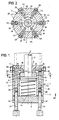
- a hydraulic pulling device which consists essentially of a one-piece cylinder body 1 with a fixed end wall 2 and an attached end wall 3.
- This cylinder body 1 contains a working cylinder 4 in the form of a cylindrical chamber concentric with the axis 5 of the cylinder body 1, which extends axially between the end walls 2 and 3 and in which there is a working piston 6, the piston rod 7 of which is through a central bore 8 of the end wall 2 protrudes outwards.
- the working piston 6 is sealed by an annular seal 9 on the inner surface of the working cylinder 4, and it is under the influence of a compression spring 10 which is supported on the inside of the end wall 3 and which presses it against the end wall 2.
- a total of six pressure cylinders 12, 13, 14, 15, 16 and 17 are arranged in the wall 11 that closes the working cylinder 4 in the form of axially parallel bores with different diameters, which pass through pressure medium channels 18, 19, 20, 21, 22 and 23 are each individually connected to the pressure chamber 24 located between the working piston 6 and the end wall 2.
- the individual pressure medium channels each consist of a radial bore 25 and two axial bores 26 and 27, the axial bores 26 each running coaxially with one of the pressure cylinders 12 to 17 and the axial bores 27 being arranged in the annular surface 28 surrounding the bore 8 of the end wall 2.
- the radial bores 25 are each sealed tightly to the outside by sealing screws 29.
- each pressure piston 30 are axially movable, which can be actuated individually by threaded spindles 31.
- These threaded spindles 31 are each arranged in threaded bores 32 arranged coaxially with the individual pressure cylinders 12 to 17 in the end wall 3 such that they each experience an axial displacement during rotation in one direction or the other.
- Their diameters are each kept smaller than the diameters of the pressure cylinders, so that they can plunge unhindered into them in order to move their pressure pistons 30.
- the end wall 3 is connected to the cylinder body 1 by means of screws (not shown), the chamber of the working cylinder in which the compression spring is located and the chambers of the pressure cylinders 12 to 17, into which the threaded spindles 31 are immersed, to be ventilated.
- the pressure chamber 24 of the working cylinder 4 and with it Connected spaces of the pressure cylinders 12 to 17 including the pressure medium channels 18 to 23 are each filled with a liquid or paste-like pressure medium 35, which can consist, for example, of hydraulic oil or a pasty fat. If one or more of the threaded spindles are rotated one after the other in the direction of arrow 36 into a pressure cylinder 12 to 17, the pressure medium 35 located in front of it is pressed by the correspondingly moving pressure piston 30 through the connecting channel or channels 18 to 23 into the pressure chamber 28 of the working cylinder 4 and thereby the working piston 6 moves with its piston rod 7 in the opposite direction.
- a liquid or paste-like pressure medium 35 which can consist, for example, of hydraulic oil or a pasty fat.
- the compression spring 10 ensures that the pressure piston 6 moves again in the direction of arrow 36 against the end wall 2 and returns to its starting position.
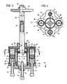
- the pressure cylinders 41 to 44 each sit sealingly in cylindrical recesses or blind bores 48, 49, 50, 51, which are arranged at the same radial spacing around a central threaded bore 52 at the same angular spacing, that is to say offset by 90 ° to one another, and through Pressure medium channels 53, 54, 55, 56 are each individually connected to the pressure chamber 57 of the working cylinder 40.
- the one end section of the tube forming the working cylinder 40 is provided with an external thread 58 which is screwed into the threaded bore 52 of the end wall plate 45 in a sealing manner.
- the forehead is in its center wall plate 45 has an axial bore 60 provided with sealing rings 59 and a concentric threaded shoulder 61.
- the piston rod 62 of a working piston 63 working cylinder 40 is guided.
- the piston rod 62 is provided at its outer end with a threaded pin 64 of smaller diameter, onto which an exchangeable pull rod 65 is screwed as an extension, and a threaded section 66 is provided at its free end with a screwed-on, plate-like pressure piece 67.
- the end wall plate 45 and the ring plate 46 which have a circular basic shape per se, are each provided with round radial incisions 68 between the individual pressure cylinders 41 to 44, which give them a cross-like shape.
- the end sections of the pressure cylinders 41 to 44 opposite the end wall plate 45 are each held in cylindrical end recesses 69 of the ring plate 46, which is guided in a centered manner by means of a central bore 70 on the tube forming the working cylinder 40 and is penetrated by it.
- the end section 71 of the working cylinder 40 protruding from the bore 70 of the ring plate 46 is also provided with an external thread 72, onto which an internal thread of the cylindrical end wall 47 is screwed. In this way, the end wall 47 with the tube forming the working cylinder 40 and the ring plate 46 with the pressure cylinders 41 to 44 connected.
- a ventilation hole 73 for the working cylinder 40.
- a threaded spindle 75 is screwed in, which can be used both as a stroke limit stop for the working piston 63 and also to push the working piston 33 back into its starting position from its position which it occupies at the end of a working stroke.
- the individual pressure cylinders 41 to 44 each have axially movable pressure pistons 76 which lie closely against the inner surfaces of the pressure cylinders and which can be individually actuated by threaded spindles 77. These threaded spindles 77 are each screwed in a coaxial arrangement to the individual pressure cylinders 41 to 44 in threaded bores 78 of the ring plate 46 and serve in the same way for actuating the pressure pistons 76 as the threaded spindle 31 for actuating the pressure pistons 30 in the embodiment of FIGS. 1 and 2 .
- a sealing sleeve 80 On the annular surface 79 of the working piston 63 which surrounds the piston rod 62, a sealing sleeve 80 is arranged, which seals both on the piston rod 62 and on the Inner surface of the pressure cylinder 40 abuts, but is otherwise not connected to the working piston 63.
- the sealing sleeve 80 With a manual movement of the working piston 63 in the direction of arrow 81 and stationary pressure piston 76, the sealing sleeve 80 thus has the possibility of remaining in its current position, so that no negative pressure arises in the pressure chamber 57, which leads to a displacement of the pressure piston 76 in the individual pressure cylinders 41 to 44 could lead.
- an O-ring 82 made of hard rubber, for example, is inserted between its outer and inner ring lips.
- the pressure medium 83 with which the cavities of the pressure cylinders 41 to 44, as well as the connecting channels 53 to 56 and the pressure chamber 57 of the working cylinder 40, are filled between the pressure pistons 76 and the end wall plate 45, consists of a pasty grease, such as is used for wheel bearings is used on motor vehicles.
- the method of operation is in principle the same as in the exemplary embodiment in FIGS. 1 and 2.
- the presence of the threaded shoulder 61 on the end wall plate 45 makes it possible to screw the gas control device, for example, into a support plate or the like.
Landscapes
- Engineering & Computer Science (AREA)
- Mechanical Engineering (AREA)
- Physics & Mathematics (AREA)
- Fluid Mechanics (AREA)
- General Engineering & Computer Science (AREA)
- Actuator (AREA)
- Rotary Presses (AREA)
Applications Claiming Priority (2)
| Application Number | Priority Date | Filing Date | Title |
|---|---|---|---|
| DE3730214 | 1987-09-09 | ||
| DE19873730214 DE3730214A1 (de) | 1987-09-09 | 1987-09-09 | Hydraulische ziehvorrichtung |
Publications (2)
| Publication Number | Publication Date |
|---|---|
| EP0306737A2 true EP0306737A2 (fr) | 1989-03-15 |
| EP0306737A3 EP0306737A3 (fr) | 1989-12-20 |
Family
ID=6335582
Family Applications (1)
| Application Number | Title | Priority Date | Filing Date |
|---|---|---|---|
| EP88113294A Withdrawn EP0306737A3 (fr) | 1987-09-09 | 1988-08-17 | Dispositif de traction hydraulique |
Country Status (2)
| Country | Link |
|---|---|
| EP (1) | EP0306737A3 (fr) |
| DE (1) | DE3730214A1 (fr) |
Cited By (5)
| Publication number | Priority date | Publication date | Assignee | Title |
|---|---|---|---|---|
| FR2748297A1 (fr) * | 1995-05-31 | 1997-11-07 | Pournin Dominique | Systeme de transmission hydraulique micrometrique |
| CN109514492A (zh) * | 2018-11-08 | 2019-03-26 | 安徽岳塑汽车工业股份有限公司 | 一种衬套压装装置 |
| EP3569353A1 (fr) * | 2018-05-18 | 2019-11-20 | TMD Friction Services GmbH | Dispositif de commande |
| CN110901754A (zh) * | 2019-11-28 | 2020-03-24 | 浙江汇迅骏机电技术有限公司 | 一种助力转向泵驱动电机 |
| US11123848B2 (en) * | 2016-01-11 | 2021-09-21 | General Electric Company | Fastener removal tools and methods |
Families Citing this family (1)
| Publication number | Priority date | Publication date | Assignee | Title |
|---|---|---|---|---|
| DE19851444B4 (de) * | 1998-11-09 | 2008-05-15 | Atlas Copco Construction Tools Gmbh | Ausbauvorrichtung für die äußere, als Werkzeugabstützung dienende Führungsbuchse im Gehäuse eines Schlagwerks |
Family Cites Families (2)
| Publication number | Priority date | Publication date | Assignee | Title |
|---|---|---|---|---|
| AT137733B (de) * | 1932-02-19 | 1934-05-25 | Steiner Nfg F | Lastheber, insbesondere Wagenheber. |
| DE1253649B (de) * | 1961-05-02 | 1967-11-02 | Kleinbongartz & Kaiser | Hydraulische Abziehvorrichtung zum Abziehen von Zahnraedern, Kugellagern und anderen rad- oder ring- oder scheibenfoermigen Werkstuecken |
-
1987
- 1987-09-09 DE DE19873730214 patent/DE3730214A1/de active Granted
-
1988
- 1988-08-17 EP EP88113294A patent/EP0306737A3/fr not_active Withdrawn
Cited By (6)
| Publication number | Priority date | Publication date | Assignee | Title |
|---|---|---|---|---|
| FR2748297A1 (fr) * | 1995-05-31 | 1997-11-07 | Pournin Dominique | Systeme de transmission hydraulique micrometrique |
| US11123848B2 (en) * | 2016-01-11 | 2021-09-21 | General Electric Company | Fastener removal tools and methods |
| EP3569353A1 (fr) * | 2018-05-18 | 2019-11-20 | TMD Friction Services GmbH | Dispositif de commande |
| CN109514492A (zh) * | 2018-11-08 | 2019-03-26 | 安徽岳塑汽车工业股份有限公司 | 一种衬套压装装置 |
| CN110901754A (zh) * | 2019-11-28 | 2020-03-24 | 浙江汇迅骏机电技术有限公司 | 一种助力转向泵驱动电机 |
| CN110901754B (zh) * | 2019-11-28 | 2021-03-26 | 浙江汇迅骏机电技术有限公司 | 一种助力转向泵驱动电机 |
Also Published As
| Publication number | Publication date |
|---|---|
| EP0306737A3 (fr) | 1989-12-20 |
| DE3730214A1 (de) | 1989-03-30 |
| DE3730214C2 (fr) | 1989-07-06 |
Similar Documents
| Publication | Publication Date | Title |
|---|---|---|
| DE3234027C1 (de) | Vorrichtung zum Kontern und Brechen von Gewindeverbindungen | |
| WO1995017292A1 (fr) | Dispositif de fermeture d'un moule pour machine a mouler par injection | |
| DE2818337B1 (de) | Druckuebersetzter hydropneumatischer Antrieb | |
| DE3637823C2 (de) | Hilfskraftbetätigtes Spannfutter | |
| DE2844475A1 (de) | Radialpresse fuer werkstuecke mit zylindrischer aussenflaeche mit mehreren, im kreis angeordneten pressbacken | |
| DE2045528B2 (de) | Verbindungseinrichtung für Stirnwand und Gehäusemantel eines Fluidzylinders | |
| DE2255308C3 (de) | Vorrichtung zur Wegesteuerung des Druckmittels zu und von einem doppeltwirkenden pneumatischen Servomotor | |
| DE2532408B2 (de) | Druckluftantrieb für Werkzeuge | |
| DE2511988A1 (de) | Halter fuer rohrfoermige koerper | |
| DE2157274A1 (de) | Vorrichtung zum Verformen bzw. Verpressen | |
| DE3730214C2 (fr) | ||
| DE3804163A1 (de) | Druckmittelbetriebene stell- oder arbeitsvorrichtung | |
| DE3341424C2 (de) | Antriebsvorrichtung | |
| DE19822439A1 (de) | Vorrichtung zur Durchführung von Betätigungen in einer Druckmaschine | |
| DE3512241A1 (de) | Radialpresse | |
| DE2916191A1 (de) | Krafteinheit als antriebsvorrichtung, z.b. zum umformen, verformen, verdichten, schlagen und antreiben | |
| DE2510384B2 (de) | Zahnaerztliches handstueck | |
| DE453698C (de) | Walzenlager mit hydraulischer Anpressvorrichtung | |
| DE10323805B3 (de) | Dornverriegelungseinheit für Druckwalzendorne in einer Rotationsdruckmaschine | |
| DE69938597T2 (de) | Bearbeitungskopf | |
| DE202010012321U1 (de) | Vorrichtung, insbesondere Stangengreifer, zum Greifen, Halten und Freigeben von zu bearbeitendem Material | |
| DE60028836T2 (de) | Pneumatischer schraubstock mit hydraulischem kraftverstärker | |
| DE2660470C2 (de) | Druckluftbetriebene Hydraulikpumpe | |
| DE1301252B (de) | Zylindereinheit mit Druckuebersetzung | |
| DE2847951A1 (de) | Hydraulisch betaetigter hohlspannzylinder fuer spanneinrichtungen an einer rotierenden spindel |
Legal Events
| Date | Code | Title | Description |
|---|---|---|---|
| PUAI | Public reference made under article 153(3) epc to a published international application that has entered the european phase |
Free format text: ORIGINAL CODE: 0009012 |
|
| AK | Designated contracting states |
Kind code of ref document: A2 Designated state(s): ES FR GB IT SE |
|
| PUAL | Search report despatched |
Free format text: ORIGINAL CODE: 0009013 |
|
| AK | Designated contracting states |
Kind code of ref document: A3 Designated state(s): ES FR GB IT SE |
|
| 17P | Request for examination filed |
Effective date: 19900127 |
|
| STAA | Information on the status of an ep patent application or granted ep patent |
Free format text: STATUS: THE APPLICATION HAS BEEN WITHDRAWN |
|
| 17Q | First examination report despatched |
Effective date: 19910320 |
|
| 18W | Application withdrawn |
Withdrawal date: 19910415 |
|
| R18W | Application withdrawn (corrected) |
Effective date: 19910415 |