EP0306776B1 - Unité d'escalier de montage pour un escalier - Google Patents
Unité d'escalier de montage pour un escalier Download PDFInfo
- Publication number
- EP0306776B1 EP0306776B1 EP88113856A EP88113856A EP0306776B1 EP 0306776 B1 EP0306776 B1 EP 0306776B1 EP 88113856 A EP88113856 A EP 88113856A EP 88113856 A EP88113856 A EP 88113856A EP 0306776 B1 EP0306776 B1 EP 0306776B1
- Authority
- EP
- European Patent Office
- Prior art keywords
- cylindrical member
- cylindrical
- cylinder
- bolt hole
- stair
- Prior art date
- Legal status (The legal status is an assumption and is not a legal conclusion. Google has not performed a legal analysis and makes no representation as to the accuracy of the status listed.)
- Expired
Links
- 238000000034 method Methods 0.000 description 3
- 238000012790 confirmation Methods 0.000 description 1
- 238000003780 insertion Methods 0.000 description 1
- 230000037431 insertion Effects 0.000 description 1
Images

Classifications
-
- E—FIXED CONSTRUCTIONS
- E04—BUILDING
- E04F—FINISHING WORK ON BUILDINGS, e.g. STAIRS, FLOORS
- E04F11/00—Stairways, ramps, or like structures; Balustrades; Handrails
- E04F11/02—Stairways; Layouts thereof
-
- E—FIXED CONSTRUCTIONS
- E04—BUILDING
- E04F—FINISHING WORK ON BUILDINGS, e.g. STAIRS, FLOORS
- E04F11/00—Stairways, ramps, or like structures; Balustrades; Handrails
- E04F11/02—Stairways; Layouts thereof
- E04F11/022—Stairways; Layouts thereof characterised by the supporting structure
- E04F11/035—Stairways consisting of a plurality of assembled modular parts without further support
-
- E—FIXED CONSTRUCTIONS
- E04—BUILDING
- E04F—FINISHING WORK ON BUILDINGS, e.g. STAIRS, FLOORS
- E04F11/00—Stairways, ramps, or like structures; Balustrades; Handrails
- E04F11/02—Stairways; Layouts thereof
- E04F11/104—Treads
- E04F11/112—Treads of metal or with an upper layer of metal
Definitions
- the invention relates to a stair assembly unit for a staircase, the stair assembly unit including a lower stair unit having a first cylindrical member projecting upwards from a first element and an upper stair unit having a second cylindrical member projecting downwards from a second element, wherein the first cylindrical member can be inserted into the second cylindrical member and can rotate freely, the height and angle between the lower stair unit and the upper stair unit being adjustable by means of a fixing mechanism.
- Stair assembly units of this kind make it possible to construct a curved staircase without using support poles.
- an element of the stair assembly unit having only one cylindrical member is fixed to one of the two floors.
- One of the cylindrical members of another element having a cylindrical element projecting therefrom at each end, but in opposite directions, is inserted into the cylindrical member of the element fixed to the floor board.
- a number of other elements may be added in this manner.
- another element having only one cylindrical member is fitted into the cylinder of the preceding element and fixed to the other floor board.
- the cylinders are disposed with their axes in vertical direction and treads are fitted onto the upper surface of each horizontal element, to form the staircase. Because the cylinders are rotatable with respect to each other, the successive treads of the staircase can be set at a desired angle with respect to each other, thus providing the desired curvature. It is necessary to adjust the depth to which one cylinder of a pair is inserted in the other cylinder, in order to provide a desired height of each tread above the preceding tread and to fit a whole number of stair assembly units into the available vertical space between the upper and the lower floor boards.
- the document DE-A-2 623 523 describes a supportimg structure for a staircase made up of a series of units, wherein an upper stair unit has an upper element, a cylindrical member projecting downwards from the upper element, an anchor plate fixed inside the upper element, and an opening in the surface of the element to enable the insertion of a bolt to pass through an opening in the anchor plate and along the axis of the cylindrical member.
- the inner circumference of the cylindrical member is provided with a screw thread, and a separate cylindrical member has a screw thread on the upper portion of its outer circumference, so that the separate cylindrical member can be screwed into the cylindrical member of the upper element.
- the lower end of the separate cylindrical member is provided with a square base plate, the side edges of which permit the engagement of a tool for rotating the separate cylindrical member.
- a lower stair unit has a lower element, inside which a support plate is fixed.
- the square base plate of the separate cylindrical member is supported on the upper surface of the lower element and the bolt passes through an opening in the base plate of the separate cylindrical member and an opening in the support plate and mates with a nut secured to the underside of the support plate. Fine adjustment of the height between the upper element and the lower element is made by rotating the separate cylinder member with the tool, wherein the side edges of the square base plate may be aligned with the side edges of the lower element.
- Figures 1 and 2 show a first embodiment of the present invention.
- Reference numeral 61 represents a first cylindrical member of a lower stair unit 62, which member projects upward beyond a first element 63
- reference numeral 64 represents a movable cylinder screwed to the cylindrical member 61
- Reference numeral 65 represents a second cylindrical member of an upper stair unit 62, which member projects downward from below a second element 63.
- the inner diameter of the cylindrical member 65 is considerably greater than the outer diameter of the cylindrical member 61, so that the letter can be inserted and can rotate freely.
- Reference numeral 66 represents a bolt and 67 a nut.
- the cylindrical member 61 having a smaller diameter is open at its upper end portion and has a screw thread portion 68 around its inner circumference in a predetermined depth.
- the movable cylinder 64 consists of a first cylindrical tube 69 having an outer diameter equal to that of the cylindrical member 61, a second cylindrical tube 70 fixed to the inner circumference at the lower end portion of the cylindrical tube 69 and having a screw thread around its outer circumference so as to mate with the cylindrical screw thread portion 68, and a disc-like lid member 71 fixed to the upper end of the cylindrical tube 69 and having a bolt hole 71a bored on its axis.
- a nut 67 is fixed on the lower surface of the lid member 71 at a position corresponding to the bolt hole 71a.
- the downwardly projecting cylindrical member 65 is equipped with a disc-like anchor member 73 at a position considerably below the upper surface 63a of the element 63, that is to say, on the inner circumferential surface where the head of the bolt 66 is slightly concealed.
- a bolt hole 73a is bored on the anchor member 73 on its axis.
- the anchor member 73 includes an outer rim 73b and a radial notch 93c around the bolt hole 73a, so that the movable cylinder 64 can be rotated by the operating handle 30 from above the anchor member 73 through the notch 93c.
- the movable cylinder 64 is screwed to the screw thread portion 68 of the cylindrical member 61, and then rotated so as to adjust the height (h2 + ⁇ ) from the upper surface of the movable cylinder 64 to the upper surface 63a of the lower element 63 to that desired.
- the cylindrical member 65 of the upper stair unit 62 is lowered from above so that the anchor member 73 of the cylindrical member 65 is put onto the movable cylinder 64.
- the angle between the upper and lower stair units 62, 62 is adjusted, and finally, the bolt 66 is inserted through both bolt holes 73a, 71a and then mated with the nut 67 to carry out temporary fixing. Thereafter, the same procedures are repeated for the remaining stair units to complete temporary assembly of the units.
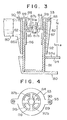
- Numeral 81 represents a first cylindrical member with a small diameter having an opening at the top.
- a cylinder 86 equipped with a screw thread portion 86a of a predetermined length on its outer circumference is fixed at the upper end on the inner circumference of the first cylindrical member 81.
- a movable cylinder 82 has an outer diameter which is the same as that of the cylindrical member 81, and a thread portion 82a is formed on the inner circumference at the lower portion of the cylinder 82.
- a disc-like fixing plate 87 is fixed at the middle portion of the inner circumference of the movable cylinder 82.
- a bolt hole 87a is bored on the fixing plate 87 on its axis, and a nut 85 is fixed on the lower surface of the fixing plate 87.
- a plurality of holes 87b for receiving an operating handle similar to the handle 30 shown in Fig. 5 are formed around the bolt hole 87a.
- the length of the cylinder 82 is decided by arbitrarily determining the vertical movable range of the stair units 80.
- An anchor member 83 consists of a recessed cylinder 88, a flange 89 formed around the upper end of the cylinder 88 and a pair of screw fitting plates 90 extending outwards from the flange 89.
- the recessed cylinder 88 is constructed so that it can be inserted into the movable cylinder 82, and openings 91b are formed around a bolt hole 91a that is bored on the axis of a bottom plate 91 of the cylinder 88.
- the outer diameter of the flange 89 is decided so that it can be put on the upper surface of a second cylindrical member 92 having a greater diameter.
- the anchor member 83 is fixed to the upper stair unit by screws 93 fitted to a screw fitting plate
- the movable cylinder 82 is screwed to the cylinder 86 that is fixed to the first cylindrical member 81 and then rotated so that the height (h2 + ⁇ ) from the upper surface of the fixing plate 87 of the movable cylinder 82 to the upper surface 94a of the lower element 94 is adjusted as desired.
- the lower stair unit 80 is inserted from below into the second cylindrical member 92 of the upper stair unit 80.
- the bolt 84 is inserted into the bolt hole 87a from above the anchor member 83 and is loosely mated with the nut 85, thereby fixing the upper and lower units 80, 80.
- temporary assembly is effected. The same procedures are thereafter repeated to complete the temporary assembly.
- the movable cylinder 82 is rotated with the operating handle 30 through the openings 91b of the anchor member 83 in order to distribute the difference between the dimension on the drawing and the dimension at the site of assembly or the error occurring at the time of assembly of each stair unit.
- the bolt 84 is screwed and fixed, thereby completing the final assembly.
- the embodiment can eliminate the problem that shake or eccentricity of axes occurs when the stair units 80, 80 are fixed to each other.
- anchor member 83 it is not always necessary that the anchor member 83 be formed integrally. Instead, the bottom plate 91 and the cylinder 88 may be separately made and may be anchored or supported in the state in which they do not move downward.
- the present invention makes it extremely easy to carry out the fine adjustment at the time of final assembly after the rough adjustment at the time of temporary assembly. Accordingly, the present invention provides a great practical advantage.
Landscapes
- Engineering & Computer Science (AREA)
- Architecture (AREA)
- Civil Engineering (AREA)
- Structural Engineering (AREA)
- Steps, Ramps, And Handrails (AREA)
- Mutual Connection Of Rods And Tubes (AREA)
- Legs For Furniture In General (AREA)
- Ladders (AREA)
- Flanged Joints, Insulating Joints, And Other Joints (AREA)
- Domestic Plumbing Installations (AREA)
- Switches Operated By Changes In Physical Conditions (AREA)
- Types And Forms Of Lifts (AREA)
- Conveying And Assembling Of Building Elements In Situ (AREA)
Claims (2)
_ une unité d'escalier inférieure (62) ayant un premier membre cylindrique (61) avançant vers le haut depuis un premier élément (63) et étant ouvert au niveau de sa partie terminale supérieure et ayant une partie filetée (68) autour de sa circonférence intérieure,
_ une unité d'escalier supérieure (62) ayant un second membre cylindrique (65) avançant vers le bas depuis un second élément (63), dans laquelle le premier membre cylindrique (61) peut être inséré dans le second membre cylindrique (65) et peut tourner librement,
_ un cylindre mobile (64) composé d'un premier tube cylindrique (69) ayant un diamètre extérieur égal à celui du premier membre cylindrique (61), d'un second tube cylindrique (70) fixé à la circonférence intérieure au niveau de la partie terminale inférieure du premier tube cylindrique (69) et ayant un filetage autour de sa circonférence extérieure de manière à s'apparier avec la partie filetée cylindrique (68), et d'un élément de couvercle (71) en forme de disque, fixé à l'extrémité supérieure du premier tube cylindrique (69) et ayant un trou de boulon (71a) percé sur son axe et des trous (72) percés autour du trou de boulon (71a) pour recevoir une poignée de manoeuvre rotative (30),
_ un écrou (67) fixé sur la surface inférieure de l'élément de couvercle (71) à une position correspondant au trou de boulon (71a),
_ un élément d'ancrage (73) en forme de disque ayant un trou de boulon (73a) percé sur son axe, et
_ un boulon (66) adapté pour être inséré à travers les deux trous de boulon (71a, 73a) et ensuite apparié avec l'écrou (67), le second membre cylindrique (65) étant équipé de l'élément d'ancrage (73) à une position au-dessous d'une surface supérieure (63a) du second élément (63) où la tête du boulon (66) est dissimulée,
_ dans laquelle l'élément d'ancrage (73) comprend des encoches radiales (93c) autour du trou de boulon (73a), de sorte qu'on peut faire tourner le cylindre mobile (64) par la poignée de manoeuvre (30) par dessus l'élément d'ancrage (73) à travers les encoches (93c).
_ une unité d'escalier inférieure (80) ayant un premier membre cylindrique (81) avançant vers le haut depuis un premier élément (94) et ayant une ouverture au sommet,
_ une unité d'escalier supérieure (80) ayant un second membre cylindrique (92) avançant vers le bas depuis un second élément, dans laquelle le premier membre cylindrique (81) peut être inséré dans le second membre cylindrique (92) et peut tourner librement,
_ un cylindre (86) équipé d'une partie filetée (86a) d'une longueur prédéterminée sur sa circonférerence extérieure et fixé sur sa circonférence intérieure à l'extrémité supérieure du premier membre cylindrique (81),
_ un cylindre mobile (82) ayant un diamètre extérieur qui est identique à celui du premier membre cylindrique (81) et ayant une partie filetée (82a) formée sur la circonférence intérieure à la partie inférieure et étant adapté pour être vissé au cylindre (86),
_ une plaque de fixation (87) en forme de disque, fixée au milieu de la circonférence intérieure du cylindre mobile (82) et ayant un trou de boulon (87a) percé sur son axe, une pluralité de trous (87b) pour recevoir une poignée de manoeuvre (30) étant formés autour du trou de boulon (87a),
_ un écrou (85) fixé sur la surface inférieure de la plaque de fixation (87),
_ un élément d'ancrage (83) composé d'un cylindre évidé (88), d'un rebord (89) formé autour de l'extrémité supérieure du cylindre évidé (88) et d'une paire de plaques de fixation à vis (90) s'étendant vers l'extérieur depuis le rebord (89), le cylindre évidé (88) étant construit pour pouvoir être inséré dans le cylindre mobile (82), le diamètre extérieur du rebord (89) étant déterminé pour qu'il puisse être posé sur la surface supérieure du second membre cylindrique (92), et l'élément d'ancrage (83) étant adapté pour être fixé à l'unité d'escalier supérieure par une vis (93) qui est fixée à chaque plaque de fixation à vis (90),
_ une plaque inférieure (91) du cylindre évidé (88) ayant des ouvertures (91b) formées autour d'un trou de boulon (91a) qui est percé sur l'axe de la plaque inférieure (91), et
_ un boulon (84) adapté pour être inséré dans le trou de boulon (87a) par dessus l'élément d'ancrage (83) pour être apparié avec l'écrou (85), ce qui fixe de cette manière les unités d'escalier supérieure et inférieure (80, 80),
_ dans laquelle on peut faire tourner le cylindre mobile (82) par la poignée de manoeuvre (30) à travers les ouvertures (91b) de l'élément d'ancrage (83) lorsque le boulon (84) est apparié de façon non serrée avec l'écrou (85), et le premier membre cylindrique (81) et le cylindre mobile (82) sont adaptés pour être insérés dans le second membre cylindrique (92) sensiblement au niveau de leur surface circonférentielle intérieure toute entière.
Applications Claiming Priority (4)
| Application Number | Priority Date | Filing Date | Title |
|---|---|---|---|
| JP158965/82 | 1982-09-14 | ||
| JP158964/82 | 1982-09-14 | ||
| JP57158964A JPS5948558A (ja) | 1982-09-14 | 1982-09-14 | 組立式階段 |
| JP57158965A JPS5948559A (ja) | 1982-09-14 | 1982-09-14 | 組立式階段 |
Related Parent Applications (1)
| Application Number | Title | Priority Date | Filing Date |
|---|---|---|---|
| EP83108858.8 Division | 1983-09-08 |
Publications (3)
| Publication Number | Publication Date |
|---|---|
| EP0306776A2 EP0306776A2 (fr) | 1989-03-15 |
| EP0306776A3 EP0306776A3 (en) | 1989-07-26 |
| EP0306776B1 true EP0306776B1 (fr) | 1991-07-03 |
Family
ID=26485923
Family Applications (2)
| Application Number | Title | Priority Date | Filing Date |
|---|---|---|---|
| EP88113856A Expired EP0306776B1 (fr) | 1982-09-14 | 1983-09-08 | Unité d'escalier de montage pour un escalier |
| EP83108858A Expired EP0106125B1 (fr) | 1982-09-14 | 1983-09-08 | Marche pour un escalier |
Family Applications After (1)
| Application Number | Title | Priority Date | Filing Date |
|---|---|---|---|
| EP83108858A Expired EP0106125B1 (fr) | 1982-09-14 | 1983-09-08 | Marche pour un escalier |
Country Status (9)
| Country | Link |
|---|---|
| US (1) | US4557085A (fr) |
| EP (2) | EP0306776B1 (fr) |
| KR (1) | KR870000251B1 (fr) |
| AT (1) | ATE64976T1 (fr) |
| AU (1) | AU555328B2 (fr) |
| CA (1) | CA1199158A (fr) |
| DE (2) | DE3381793D1 (fr) |
| NZ (1) | NZ205548A (fr) |
| PH (1) | PH20137A (fr) |
Families Citing this family (12)
| Publication number | Priority date | Publication date | Assignee | Title |
|---|---|---|---|---|
| US4619084A (en) * | 1985-01-28 | 1986-10-28 | Snitman Bernard H | Articulating, self-supporting staircase |
| GB2179979B (en) * | 1985-09-06 | 1989-08-16 | Romulus Technology Ltd | Stair constructions |
| IT1201580B (it) * | 1986-10-16 | 1989-02-02 | Indexstudio Sas Di Molinazzi & | Supporto modulare per gradini di scale |
| CA2007032C (fr) * | 1989-01-27 | 1997-09-30 | Keiichiro Yamazaki | Escalier escamotable |
| US5134820A (en) * | 1990-10-16 | 1992-08-04 | Liu Ing Nan | Adjustable built-up stair |
| IT1260911B (it) * | 1993-03-16 | 1996-04-29 | Roberto Molinazzi | Elemento di sopporto modulare atto a costituire da appoggio per un gradino di una scala. |
| US5502933A (en) * | 1993-12-10 | 1996-04-02 | Skillern; Charles T. | Modular staircase system |
| DE10150461C1 (de) * | 2001-10-16 | 2003-04-24 | Bernhard Schuster | Freitragende Mittelholm-Treppe |
| CN101460687B (zh) * | 2006-04-28 | 2012-03-14 | 阿尔比尼&峰塔诺特股份公司 | 用于模块式楼梯的台阶以及相关楼梯 |
| PH12014000076B1 (en) * | 2013-07-01 | 2024-01-10 | Priscila F Kimes | Improved processes in the preparation of coconut meat based composition and films |
| US9840847B2 (en) | 2015-09-02 | 2017-12-12 | Moritz O. Bergmeyer | Curved staircase |
| US10106986B2 (en) | 2015-09-02 | 2018-10-23 | Moritz O. Bergmeyer | Curved pathway |
Family Cites Families (8)
| Publication number | Priority date | Publication date | Assignee | Title |
|---|---|---|---|---|
| DE6606476U (de) * | 1966-02-08 | 1970-10-02 | Ernst Herbert | Bauelement, insbesondere fuer eine vorzufertigende treppe. |
| DE2256370A1 (de) * | 1972-11-17 | 1974-05-22 | Grande Manfred | Tragkonstruktion, insbesondere fuer treppen |
| FR2268918A1 (en) * | 1974-04-25 | 1975-11-21 | Hamm Wilfried | Self-supporting spiral staircase - has balls between tread carriers wedged by collars on tensioner screw |
| DE2623523A1 (de) * | 1976-05-26 | 1977-12-15 | Zimmermann Erich | Treppentragkonstruktion |
| US4296577A (en) * | 1979-10-22 | 1981-10-27 | Schuette Heinz G | Helical staircase support |
| DE3031095A1 (de) * | 1980-08-16 | 1982-07-29 | Frewa Baudekoration Und Vertriebsgesellschaft Mbh & Co Kontakt- Und Verkaufs Kg, 6550 Bad Kreuznach | Gliedertreppe |
| US4373609A (en) * | 1980-12-22 | 1983-02-15 | Victor De Donato | Stairway stringers constructed of cast, readily-assembled units |
| JPS5789052A (en) * | 1981-05-09 | 1982-06-03 | Yamazaki Keiichiro | Assembly of staircase unit |
-
1983
- 1983-09-08 DE DE8383108858T patent/DE3381793D1/de not_active Expired - Lifetime
- 1983-09-08 AT AT88113856T patent/ATE64976T1/de active
- 1983-09-08 DE DE8888113856T patent/DE3382330D1/de not_active Expired - Lifetime
- 1983-09-08 EP EP88113856A patent/EP0306776B1/fr not_active Expired
- 1983-09-08 EP EP83108858A patent/EP0106125B1/fr not_active Expired
- 1983-09-09 CA CA000436333A patent/CA1199158A/fr not_active Expired
- 1983-09-12 US US06/530,993 patent/US4557085A/en not_active Expired - Fee Related
- 1983-09-12 NZ NZ205548A patent/NZ205548A/en unknown
- 1983-09-13 AU AU19065/83A patent/AU555328B2/en not_active Ceased
- 1983-09-13 PH PH29533A patent/PH20137A/en unknown
- 1983-09-14 KR KR1019830004328A patent/KR870000251B1/ko not_active Expired
Also Published As
| Publication number | Publication date |
|---|---|
| PH20137A (en) | 1986-10-02 |
| KR870000251B1 (ko) | 1987-02-21 |
| EP0106125B1 (fr) | 1990-08-08 |
| AU555328B2 (en) | 1986-09-18 |
| AU1906583A (en) | 1984-03-22 |
| CA1199158A (fr) | 1986-01-14 |
| EP0306776A3 (en) | 1989-07-26 |
| DE3382330D1 (de) | 1991-08-08 |
| KR840005852A (ko) | 1984-11-19 |
| ATE64976T1 (de) | 1991-07-15 |
| EP0306776A2 (fr) | 1989-03-15 |
| NZ205548A (en) | 1987-10-30 |
| DE3381793D1 (de) | 1990-09-13 |
| EP0106125A2 (fr) | 1984-04-25 |
| US4557085A (en) | 1985-12-10 |
| EP0106125A3 (en) | 1985-05-22 |
Similar Documents
| Publication | Publication Date | Title |
|---|---|---|
| EP0306776B1 (fr) | Unité d'escalier de montage pour un escalier | |
| US20050072068A1 (en) | System for securing a post | |
| CA2269189C (fr) | Montant de soutien de lissage | |
| EP1948885B1 (fr) | Compensateur de pente pour socle pour planchers sureleves | |
| US4129163A (en) | Panel assembly and components thereof | |
| WO1994015043A1 (fr) | Systeme de plancher | |
| US4516367A (en) | Modular support for stairway steps | |
| EP0263916B1 (fr) | Support modulaire pour marches d'escalier | |
| US4619084A (en) | Articulating, self-supporting staircase | |
| EP0353360B1 (fr) | Combinaison d'un socle avec prise de courant | |
| GB2417500A (en) | Adjustable support base for column or the like | |
| EP0616097B1 (fr) | Elément de support modulaire adapté à former un support pour la marche d'un escalier | |
| CN119173672A (zh) | 连接器组件 | |
| WO1990012939A1 (fr) | Socle de nivellement et positionnement | |
| EP0157621A2 (fr) | Dispositif pour régler la position d'une prothèse | |
| JP4077082B2 (ja) | マンホール蓋板の傾斜調整装置 | |
| JPS6324183Y2 (fr) | ||
| JPS63272854A (ja) | フロアパネル支持装置 | |
| JP2546498Y2 (ja) | 床板などの支持装置 | |
| JPH0649734Y2 (ja) | フリーアクセスフロアの支持装置 | |
| JPS6245862A (ja) | 床板支持具 | |
| US20260062929A1 (en) | Devices configured to facilitate preparation of a surface having specified level attributes, including screeding level setting devices | |
| CN1285808C (zh) | 预铸式混凝土组合楼板 | |
| JPS5948558A (ja) | 組立式階段 | |
| KR870000252B1 (ko) | 높이 조절이 용이한 계단 유니트 고정 기구 |
Legal Events
| Date | Code | Title | Description |
|---|---|---|---|
| PUAI | Public reference made under article 153(3) epc to a published international application that has entered the european phase |
Free format text: ORIGINAL CODE: 0009012 |
|
| AC | Divisional application: reference to earlier application |
Ref document number: 106125 Country of ref document: EP |
|
| AK | Designated contracting states |
Kind code of ref document: A2 Designated state(s): AT BE CH DE FR GB IT LI LU NL SE |
|
| PUAL | Search report despatched |
Free format text: ORIGINAL CODE: 0009013 |
|
| AK | Designated contracting states |
Kind code of ref document: A3 Designated state(s): AT BE CH DE FR GB IT LI LU NL SE |
|
| 17P | Request for examination filed |
Effective date: 19890814 |
|
| 17Q | First examination report despatched |
Effective date: 19901115 |
|
| GRAA | (expected) grant |
Free format text: ORIGINAL CODE: 0009210 |
|
| AC | Divisional application: reference to earlier application |
Ref document number: 106125 Country of ref document: EP |
|
| AK | Designated contracting states |
Kind code of ref document: B1 Designated state(s): AT BE CH DE FR GB IT LI LU NL SE |
|
| ITF | It: translation for a ep patent filed | ||
| REF | Corresponds to: |
Ref document number: 64976 Country of ref document: AT Date of ref document: 19910715 Kind code of ref document: T |
|
| ET | Fr: translation filed | ||
| REF | Corresponds to: |
Ref document number: 3382330 Country of ref document: DE Date of ref document: 19910808 |
|
| PLBE | No opposition filed within time limit |
Free format text: ORIGINAL CODE: 0009261 |
|
| STAA | Information on the status of an ep patent application or granted ep patent |
Free format text: STATUS: NO OPPOSITION FILED WITHIN TIME LIMIT |
|
| 26N | No opposition filed | ||
| PGFP | Annual fee paid to national office [announced via postgrant information from national office to epo] |
Ref country code: SE Payment date: 19930816 Year of fee payment: 11 |
|
| PGFP | Annual fee paid to national office [announced via postgrant information from national office to epo] |
Ref country code: FR Payment date: 19930819 Year of fee payment: 11 |
|
| PGFP | Annual fee paid to national office [announced via postgrant information from national office to epo] |
Ref country code: GB Payment date: 19930901 Year of fee payment: 11 |
|
| PGFP | Annual fee paid to national office [announced via postgrant information from national office to epo] |
Ref country code: CH Payment date: 19930902 Year of fee payment: 11 |
|
| PGFP | Annual fee paid to national office [announced via postgrant information from national office to epo] |
Ref country code: LU Payment date: 19930908 Year of fee payment: 11 |
|
| PGFP | Annual fee paid to national office [announced via postgrant information from national office to epo] |
Ref country code: BE Payment date: 19930909 Year of fee payment: 11 |
|
| PGFP | Annual fee paid to national office [announced via postgrant information from national office to epo] |
Ref country code: NL Payment date: 19930930 Year of fee payment: 11 Ref country code: AT Payment date: 19930930 Year of fee payment: 11 |
|
| PGFP | Annual fee paid to national office [announced via postgrant information from national office to epo] |
Ref country code: DE Payment date: 19931122 Year of fee payment: 11 |
|
| EPTA | Lu: last paid annual fee | ||
| PG25 | Lapsed in a contracting state [announced via postgrant information from national office to epo] |
Ref country code: LU Free format text: LAPSE BECAUSE OF NON-PAYMENT OF DUE FEES Effective date: 19940908 Ref country code: GB Effective date: 19940908 Ref country code: AT Effective date: 19940908 |
|
| PG25 | Lapsed in a contracting state [announced via postgrant information from national office to epo] |
Ref country code: SE Effective date: 19940909 |
|
| PG25 | Lapsed in a contracting state [announced via postgrant information from national office to epo] |
Ref country code: LI Effective date: 19940930 Ref country code: CH Effective date: 19940930 Ref country code: BE Effective date: 19940930 |
|
| EAL | Se: european patent in force in sweden |
Ref document number: 88113856.4 |
|
| BERE | Be: lapsed |
Owner name: YAMAZAKI KEIICHIROU Effective date: 19940930 |
|
| PG25 | Lapsed in a contracting state [announced via postgrant information from national office to epo] |
Ref country code: NL Effective date: 19950401 |
|
| GBPC | Gb: european patent ceased through non-payment of renewal fee |
Effective date: 19940908 |
|
| NLV4 | Nl: lapsed or anulled due to non-payment of the annual fee | ||
| PG25 | Lapsed in a contracting state [announced via postgrant information from national office to epo] |
Ref country code: FR Effective date: 19950531 |
|
| REG | Reference to a national code |
Ref country code: CH Ref legal event code: PL |
|
| EUG | Se: european patent has lapsed |
Ref document number: 88113856.4 |
|
| PG25 | Lapsed in a contracting state [announced via postgrant information from national office to epo] |
Ref country code: DE Effective date: 19950701 |
|
| REG | Reference to a national code |
Ref country code: FR Ref legal event code: ST |