EP0306832A2 - Tête de mélange pour mélanger au moins deux composants de matière plastique qui forment une mousse lors de leur réaction - Google Patents
Tête de mélange pour mélanger au moins deux composants de matière plastique qui forment une mousse lors de leur réaction Download PDFInfo
- Publication number
- EP0306832A2 EP0306832A2 EP88114265A EP88114265A EP0306832A2 EP 0306832 A2 EP0306832 A2 EP 0306832A2 EP 88114265 A EP88114265 A EP 88114265A EP 88114265 A EP88114265 A EP 88114265A EP 0306832 A2 EP0306832 A2 EP 0306832A2
- Authority
- EP
- European Patent Office
- Prior art keywords
- mixing
- guide channel
- mixing chamber
- chamber
- slide
- Prior art date
- Legal status (The legal status is an assumption and is not a legal conclusion. Google has not performed a legal analysis and makes no representation as to the accuracy of the status listed.)
- Withdrawn
Links
Images

Classifications
-
- B—PERFORMING OPERATIONS; TRANSPORTING
- B29—WORKING OF PLASTICS; WORKING OF SUBSTANCES IN A PLASTIC STATE IN GENERAL
- B29B—PREPARATION OR PRETREATMENT OF THE MATERIAL TO BE SHAPED; MAKING GRANULES OR PREFORMS; RECOVERY OF PLASTICS OR OTHER CONSTITUENTS OF WASTE MATERIAL CONTAINING PLASTICS
- B29B7/00—Mixing; Kneading
- B29B7/74—Mixing; Kneading using other mixers or combinations of mixers, e.g. of dissimilar mixers ; Plant
- B29B7/76—Mixers with stream-impingement mixing head
- B29B7/7663—Mixers with stream-impingement mixing head the mixing head having an outlet tube with a reciprocating plunger, e.g. with the jets impinging in the tube
- B29B7/7673—Mixers with stream-impingement mixing head the mixing head having an outlet tube with a reciprocating plunger, e.g. with the jets impinging in the tube having additional mixing arrangements
Definitions
- the invention relates to a mixing head for mixing at least two plastic components forming foam during their reaction with a mixing chamber, to which the plastic components are fed through inlet openings and from which the component mixture enters a mold through an outlet opening and a guide channel, both the mixing chamber and an axially displaceable ejection piston or cleaning plunger is assigned to the guide channel adjoining its outlet opening.
- Mixing heads of this type are already known in various designs, as can be seen, for example, from DE-PS 23 27 269 and DE-PS 26 12 812.
- the mixing head which became known from DE-PS 23 27 269, is equipped with a guide channel for the component mixture, which in particular adjoins the outlet opening of the mixing chamber at a right angle, and for this purpose requires an ejection piston for expelling the component mixture from the mixing chamber and on the other hand, an additional cleaning plunger for cleaning the guide channel facing the mold.
- the object of the invention is to provide a mixing head of the type specified in more detail at the beginning, which enables problem-free adaptation of the post-mixing to different needs without significant repercussions on the pressure in the mixing chamber. At the same time, a minimal structural effort of the mixing head for ejecting the component mixture from the mixing chamber and for cleaning the guide channel adjoining the mixing chamber should be sought.
- This aim is achieved according to the invention - according to the characterizing part of claim 1 - by the fact that the mixing chamber and guide channel have an axis-parallel orientation to one another, that at least one post-mixing step is between the outlet opening of the mixing chamber and the inlet opening of the guide channel.
- Whirl chamber is located, which has a substantially transverse to the axes of the mixing chamber and guide channel arrangement, and that the length and / or position of the post-mixing or swirl chamber relative to the mixing chamber and guide channel can be changed.
- each post-mixing or Vortex chamber can be changed by at least one slide adjustable transversely to the mixing chamber.
- the mixing chamber and guide channel have a cross-section which is identical in shape and dimensions and is assigned one and the same ejection piston or cleaning plunger.
- each mixing chamber can preferably be determined by a slot channel and a tongue which can be slidably or slidably engaged therein. It has proven useful here if the width of the slot channel and thus also the thickness of the tongue engaging in it are dimensioned smaller than the cross-sectional dimension of the mixing chamber and the guide channel in the same direction.
- a particularly advantageous design of the mixing head results according to the invention in that - according to claim 5 - the slot channel connects in the radial direction to the outlet opening of the mixing chamber, for example in the housing, while the tongue in radial connection to the cross section of the guide channel, e.g. on the slider, which projects through its inlet opening.
- the slot channel adjoins the inlet opening of the guide channel in the slide in the radial direction, while conversely the tongue projects in radial connection to the cross-section of the mixing chamber via its outlet opening.
- the mixing head is expedient - according to claim 6 - that the mixing chamber is located in a stationary housing, while the guide channel is arranged in the slide which is adjustable relative to this housing.
- the mixing chamber and the guide channel are located in a stationary housing and are in axial alignment with one another therein, while the slide only contains an axis-parallel connecting channel via which between the mixing chamber and the guide channel two post-mixing chambers can be connected in series.
- the swirling and post-mixing effect is particularly intensified by such a configuration.
- the two post-mixing chambers are arranged symmetrically to a transverse plane of the slide, one of which adjoins the outlet opening of the mixing chamber radially, while the another opens radially into the inlet opening of the guide channel.
- the slide is adjustable by a linear drive held on the housing, in particular a piston-cylinder unit which can be pressurized with pressure medium. It can then be designed in an advantageous manner - according to claim 10 - the linear drive for the slide in addition to its two end positions in different, preferably any, intermediate positions so that the length or the volume of the post-mixing or swirl chambers can easily be different Allows conditions to be coordinated.
- the tongue of the or each post-mixing chamber is arranged to be adjustable and / or adjustable relative to the slide and parallel to its direction of movement. This measure is recommended in a particular way if - according to claim 12 - it is important that the tongue on the slide is arranged in and / or adjustable relative to the inlet opening of the guide channel, because this corresponds to that Claim 13 - the cross section of the inlet opening of the guide channel can be appropriately changed and pre-adjusted.
- the resilient support of the tongue also has the advantage that a predetermined pressure level can be maintained in the component mixture flowing through the post-mixing or swirl chambers, which can be determined by presetting. However, if this pressure level is temporarily exceeded, the tongue can shift against the biasing force acting on it and thereby lower the pressure level accordingly.
- the mixing head which - according to claim 16 - is particularly characterized in that the tongue of the or each post-mixing chamber forms part of a second slide and by means of this in the slot channel independently of the actuation of the first Slider is relocatable.
- second slide can be actuated by its own linear drive held on the housing, in particular a piston-cylinder unit that can be pressurized with pressure medium.
- the linear drive for the slide can be blocked in various, preferably any intermediate positions, in addition to its two end positions.
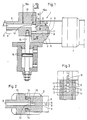
- FIG. 1 of the drawing shows a mixing head 1 which is used to mix at least two plastic components which form a foam during their chemical reaction.
- This mixing head 1 has a housing 2, in which a mixing chamber 3 is located, into which inlet openings 4 and 5 for predetermined points open for each of the plastic components.
- the mixing chamber 3 preferably has a circular cross section and can therefore be produced in the housing 2, for example as a bore.
- the mixing chamber 3 is assigned an ejection piston or cleaning plunger 6, which is axially driven by a linear drive 7, for example in the form of a piston-cylinder unit which can be acted upon by pressure medium is movable.
- a linear drive 7 for example in the form of a piston-cylinder unit which can be acted upon by pressure medium is movable.
- the flat end surface 8 of the ejection piston or cleaning plunger 6 lies in its retracted end position behind the entry plane of the two inlet openings 4 and 5 into the mixing chamber 3.
- the ejection piston or cleaning plunger 6 can also be advanced by means of the linear drive 7 into the axial position indicated by dash-dotted lines in FIG. 1.
- the mixing head 1 is further equipped with a guide channel 9 for the component mixture, which can be guided to the mold to be supplied with the component mixture.
- This guide channel 9 has a cross-sectional shape and dimension which corresponds to that of the mixing chamber 3 in the housing, that is to say, for example, is circular in cross-section. As a result, the guide channel 9 can also be easily produced as a bore.
- Mixing chamber 3 and guide channel 9 have an alignment parallel to one another and are constantly connected to one another by a remixing or swirl chamber 10.
- the mixing chamber 3 has an outlet opening 11 which has both an axial and a radial opening area towards the post-mixing or swirl chamber 10.
- the guide channel 9 is provided with an inlet opening 12 which adjoins the post-mixing or swirl chamber 10 and which has an axial orientation to this.
- a linear drive 15 is used for the transverse adjustment of the slide 13 relative to the housing 2. It consists, for example, of a piston-cylinder unit that can be pressurized and is held on the housing 2. A push and pull rod 16 of the linear drive 15 engages laterally on the slide 13 to transmit the adjustment movement.
- the slide 13 With the help of the linear drive 15, the slide 13 can be moved relative to the housing 2 between two end positions.
- the guide channel 9 located therein occupies a position parallel to the mixing chamber 3 for the component mixture.
- the guide channel 9 located therein is in the axial alignment with the mixing chamber 3 provided in the housing 2.
- the linear drive 15 is preferably designed so that with the help of the slide 13 can not only be moved into the two end positions just mentioned, but also allows the setting of various, preferably arbitrary, intermediate positions. In this way it can be achieved that the post-mixing or swirl chamber 10 between the mixing chamber 3 and the guide channel 9 can be varied continuously in terms of its volume or in its effective length between a maximum value and a minimum value.
- the component mixture is mixed by the intermediate post-mixing or Vortex chamber 10 is forced to have a double, approximately rectangular flow deflection, on the one hand when it passes from the outlet opening 11 of the mixing chamber 3 into the post-mixing or vortex chamber 10 and on the other hand when it passes from the post-mixing or vortex chamber 10 into the inlet opening 12 of the guide channel 9 .
- Fig. 3 of the drawing makes it clear that the post-mixing or swirl chamber 10 is determined by a flat slot channel 17 incorporated into the housing 2, which connects to the outlet opening 11 of the mixing chamber 3 in the radial direction and has a width which is smaller than the diameter of both the mixing chamber 3 and the guide channel 9 is dimensioned.
- a slidably or slidably engaging tongue 18 interacts, which is formed on the slide 13 and projects radially to the cross section of the guide channel 9 via its inlet opening 12 by an amount which corresponds to the depth of cut of the slot channel 17 in the housing 2 is adapted, as can be seen in FIG. 1.
- the slot channel 17 forming the post-mixing or swirl chamber 10 has its greatest effective length between the mixing chamber 3 and the guide channel 9, when the slide 13 is set, the mixing chamber 3 and guide channel are used 9 Take flight position to each other, the slot channel 17 completely filled by the tongue 18. I.e. in this case there is no post-mixing or swirl chamber 10 at all between the mixing chamber 3 and the guide channel 9.
- the volume and / or the flow path of the post-mixing or swirl chamber 10 varies virtually continuously between the value 0 and a predetermined maximum dimension and thus also to different properties of the component mixture by appropriately moving the tongue 18 in the slot channel 17 Voted can be.
- the zigzag-shaped flow deflection of the component mixture, which is forced through the post-mixing or swirl chamber 10, in any case brings about an improved mixing of the same before it reaches the guide channel 9 through the inlet opening 12 for the purpose of calming the flow.
- the mixing head 1 not only two plastic components can be brought together through the inlet openings 4 and 5 and mixed together in the mixing chamber 3. Rather, there is also the possibility of adding at least one further component, for example a gas, a liquid or also fillers.
- the inlet opening for this third component can be provided at various points within the mixing head. For example, it can be in the area of the mixing chamber 3, as is indicated by the arrow 19a. However, it can also be assigned to the post-mixing or swirl chamber 10, as indicated by the arrow 19b. Finally, it can also be assigned to the guide channel 9, as is indicated by the arrow 19c.
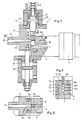
- a mixing head 21 which differs from the mixing head 1 according to FIGS. 1 to 3 essentially in that not only the mixing chamber 23, but also the guide channel 29 into the housing 22 is incorporated.
- Mixing chamber 23 and guide channel 29 are arranged in axial alignment with one another, in such a way that the axially aligned sections of the outlet opening 31 on the mixing chamber 23 and the axially aligned sections of the inlet opening 32 on the guide channel 29 face each other at a fixed distance.
- the slide 33 In the distance between the mixing chamber 23 and the guide channel 29, the slide 33 is held transversely in the housing 22, specifically in a prismatic guide 34, which can be seen in FIGS. 4 to 5.
- the transverse movement of the slide 33 in the prism guide 34 of the housing 22 can be controlled via a linear drive 35, which is preferably formed by a piston-cylinder unit to which pressure medium can be applied.
- a post-mixing or swirl chamber 30a in the radial connection to the mixing chamber 23, while on the other hand a second post-mixing or swirl chamber 30b is provided in the radial connection to the guide channel 29.
- Both post-mixing or swirl chambers 30a and 30b have a common radial plane, the post-mixing chamber 30a being connected to the mixing chamber 23 via the radial section of the outlet opening 31 and the post-mixing or.
- Vortex chamber 30b opens into the guide channel 29 via the radial section of the inlet opening 32.
- Both remixing chambers 30a and 30b are each formed by a slot channel 37a and 37b, which is machined into the housing 22 and has a flat cross section, the opening width of which is dimensioned smaller than the opening cross section of the mixing chamber 23 and the guide channel 29, as shown in FIGS. 5 and 6 reveal.
- the two tongues 38a and 38b can be moved together and simultaneously within the slot channels 37a and 37b forming the post-mixing or swirl chambers 30a and 30b are so that their volume and / or effective length transversely to the longitudinal axes of the mixing chamber 23 and guide channel 29 can be varied according to different needs.
- a connecting channel 40 is provided in front of the end surfaces of the tongues 38a and 38b delimiting the two postmixing or swirling chambers 30a and 30b, which extends axially parallel to both the mixing chamber 23 and the connecting channel 29 and also a cross-sectional shape corresponding to these and has dimension.
- the two post-mixing or swirl chambers 30a and 30b are connected in series in terms of flow, in such a way that the component mixture on its way from the mixing chamber 23 to the guide channel 29 is deflected four times in succession approximately at a right angle, thus a double zigzag -Walk through.
- the post-mixing or swirling of the component mixture is further improved compared to the design of the mixing head 1 according to FIGS. 1 to 3, and without a significant additional construction effort being required for this.
- the two post-mixing or swirl chambers 30a and 30b which are symmetrical to a transverse plane through the slide 33, can be jointly and synchronously infinitely variable in their volume or radial length relative to the mixing chamber 23 or the guide channel 29 between a value of 0 and a maximum dimension vary. If the remixing or swirl chambers 30a and 30b have the size 0, the connecting channel 40 of the slide 33 is in the axial alignment with both the mixing chamber 23 and the guide channel 29, so that the ejection piston or cleaning plunger 26 with the aid of its linear drive 27 can be advanced so far that its flat end surface 28 comes to rest flush with the front end of the guide channel 29.
- the mixing head 21 is not only suitable for processing two plastic components which are introduced through the inlet openings 24 and 25 into the mixing chamber 23, but that the supply of at least one further component, for example one Gases, a liquid or fillers is possible.
- the arrows 39a, 39b, 39c, 39d and 39e indicate that the supply of the third and / or further components is possible at at least five different locations.
- the feed point 39a is assigned to the mixing chamber 23, the feed point 39b opens into the post-mixing or swirl chamber 30a, while the feed point 39c is assigned to the connecting channel 40.
- the feed point 39d opens into the post-mixing or swirl chamber 39d, while the feed point 39e is assigned to the guide channel 29.
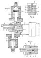
- the mixing head 1 shown in FIGS. 7 to 9 of the drawing basically has the same design and accordingly also has essentially the same mode of operation as the mixing head 1 according to FIGS. 1 to 3.
- the slot channel 17 the tongue 18 associated with the post-mixing or swirl chamber 10 is not rigidly connected to the slide 13, but rather is held in and / or adjustable parallel to the direction of movement thereof.
- a holder 41 is placed on the slide 13, in which a shaft 41 is adjustably guided parallel to the direction of movement of the slide 13 and carries at its lower end the tongue 18 protruding into the slot channel 17 of the post-mixing or swirl chamber 10.
- the shaft 42 can be adjusted in position in the holder 41 in its axial direction by means of an adjusting device or a fixing device 43, in such a way that the relative position of the tongue 18 with respect to the cross section of the inlet opening 12 to the guide channel 9 can be adjusted.
- the cross section of the inlet opening 12 to the guide channel 9 can be adjusted between a maximum and a minimum, preferably continuously, for the purpose of influencing the flow of the component mixture from the post-mixing or swirl chamber 10 into the guide channel 9.
- the setting and locking device 43 consists, for example, of a threaded bolt seated at the rear end of the shaft 42, an adjusting nut 45 supported against the upper side of the holder 41 and a lock nut 46 associated therewith. Inside the holder 41, this is supported by one of the Setting and locking device 43 facing away from an elastic return element, for example.
- a compression spring 47 which on the other hand on a collar 48 of the Shaft 42 acts and the latter thus fixed in its lower end position determined by the setting and locking device 43.
- the boundary edge 49 of the tongue 18 facing the inlet opening 12 to the guide channel 9 forms from the post-mixing or Vortex chamber 10 towards the inlet opening 12 of the guide channel 9 has a throttle edge, which brings about a partial flow acceleration of the component mixture, and also acts as a tear-off edge, behind which an additional material swirl occurs in the inlet opening 12 of the guide channel 9.
- the slide 13 is adjusted relative to the housing 2 by the linear drive 15 so that its guide channel 9 reaches the mixing chamber 3 in the axial alignment, then the tongue 18 meets an abutment stop 15 adjacent to the mixing chamber 3 in the housing and is supported by it so that the full opening cross section of the mixing chamber 3 remains free in the region of its outlet opening 11.
- the further slide movement to achieve the axial alignment between the mixing chamber 3 and the guide channel 9 is not hampered by this, however, because the compression spring 47 is elastically flexible with respect to the further slide movement.
- the special configuration of the mixing head 1 according to FIGS. 7 to 9 can also be realized in the case of need with a mixing head 21, as shown in FIGS. 5 to 6.
- the holder 41 would then have to sit on the slide 33, one or each of the two tongues 38a 38b then being carried by a shaft 42 which, via an adjusting and locking device 43 and a compression spring 47 in one of FIGS. 7, corresponds Interacts with the bracket 41.
- a mixing head 1 which corresponds in terms of its basic structure and its mode of operation with the mixing head 1 according to FIGS. 1 to 3.
- a linear drive 51 preferably in the form of a piston-cylinder unit which can be acted upon by pressure medium, is mounted on the housing 2, the push and pull rod 52 thereof at its lower end carries the tongue 18 engaging in the slot channel 17 of the post-mixing or swirl chamber 10.
- the linear drive 51 by actuating the linear drive 51, the tongue 18 can be steplessly engaged and locked within the slot channel both independently of the housing 2 and independently of the slide 13.
- the end face of the tongue 48 facing the post-mixing or swirl chamber 10 can also be used to vary the passage cross section of the inlet opening 12 into the guide channel 9. by making an opposite adjustment of the tongue 18 and slide 13 to the desired extent with the help of the linear drives 15 and 51. Also in Fig. 10 it can be seen that abutment stops 50 between the push and pull rod 52 and the housing 2 limit the end insertion position of the tongue 18 into the slot channel of the post-mixing or swirl chamber 10 and thus the full passage cross section of the mixing chamber 3 in Keep direction towards their outlet opening 11 clear.
Landscapes
- Engineering & Computer Science (AREA)
- Mechanical Engineering (AREA)
- Processing And Handling Of Plastics And Other Materials For Molding In General (AREA)
- Casting Or Compression Moulding Of Plastics Or The Like (AREA)
- Injection Moulding Of Plastics Or The Like (AREA)
Applications Claiming Priority (2)
| Application Number | Priority Date | Filing Date | Title |
|---|---|---|---|
| DE19873730472 DE3730472A1 (de) | 1987-09-11 | 1987-09-11 | Mischkopf zum vermischen mindestens zweier kunststoff-komponenten, die bei ihrer reaktion schaumstoff bilden |
| DE3730472 | 1987-09-11 |
Publications (2)
| Publication Number | Publication Date |
|---|---|
| EP0306832A2 true EP0306832A2 (fr) | 1989-03-15 |
| EP0306832A3 EP0306832A3 (fr) | 1989-05-24 |
Family
ID=6335745
Family Applications (1)
| Application Number | Title | Priority Date | Filing Date |
|---|---|---|---|
| EP88114265A Withdrawn EP0306832A3 (fr) | 1987-09-11 | 1988-09-01 | Tête de mélange pour mélanger au moins deux composants de matière plastique qui forment une mousse lors de leur réaction |
Country Status (3)
| Country | Link |
|---|---|
| EP (1) | EP0306832A3 (fr) |
| JP (1) | JPH01163005A (fr) |
| DE (1) | DE3730472A1 (fr) |
Family Cites Families (4)
| Publication number | Priority date | Publication date | Assignee | Title |
|---|---|---|---|---|
| DE3144920A1 (de) * | 1981-11-12 | 1983-05-26 | Krauss-Maffei AG, 8000 München | Mischkopf |
| DE3217016A1 (de) * | 1982-05-06 | 1983-11-10 | Bayer Ag, 5090 Leverkusen | Mischkopf zum vermischen mindestens zweier fliessfaehiger, bei ihrer reaktion vorzugsweise schaumstoff bildender komponenten |
| FR2545000A1 (fr) * | 1983-04-29 | 1984-11-02 | Mazier Paul | Dispositif pour le melange reactif de produits chimiques |
| DE3521236A1 (de) * | 1985-06-13 | 1986-12-18 | IBW Ingenieur-Büro Woitzel GmbH, 4530 Ibbenbüren | Mischkopf zum vermischen zumindest zweier kunststoff bildender komponenten |
-
1987
- 1987-09-11 DE DE19873730472 patent/DE3730472A1/de not_active Withdrawn
-
1988
- 1988-09-01 EP EP88114265A patent/EP0306832A3/fr not_active Withdrawn
- 1988-09-09 JP JP63224879A patent/JPH01163005A/ja active Granted
Also Published As
| Publication number | Publication date |
|---|---|
| JPH046529B2 (fr) | 1992-02-06 |
| JPH01163005A (ja) | 1989-06-27 |
| EP0306832A3 (fr) | 1989-05-24 |
| DE3730472A1 (de) | 1989-03-30 |
Similar Documents
| Publication | Publication Date | Title |
|---|---|---|
| DE2907938C2 (de) | Hochdruck-Mischvorrichtung | |
| DE2513492C3 (de) | Vorrichtung zum Vermischen eines flüssigen Treibmittels mit niedrigem Siedepunkt mit weiteren Komponenten zur Herstellung von Schaumstoff | |
| DE2742166C2 (de) | Vorrichtung zum Ver- und Entriegeln von Formplatten einer Spritzgieß- oder Preßform | |
| DE3040922C2 (de) | Hochdruck-Mischkopf | |
| EP0024608A1 (fr) | Procédé et dispositif de production de pièces moulées à partir d'un mélange fluide réactionnel formant une matière pleine ou expansée | |
| DE2413337B2 (de) | Mit einem Formwerkzeug kombinierte Mischeinrichtung | |
| EP0143196A2 (fr) | Tête de mixeur pour la fabrication d'un mélange capable de produire une réaction chimique et consistant en au moins deux composants de plastique | |
| DE3210978A1 (de) | Mischvorrichtung fuer mehrkomponentenkunststoffe, insbesondere polyurethan | |
| EP0084672B1 (fr) | Dispositif pour produire d'un mélange chimiquement réactif à partir d'au moins deux composants d'une matière synthétique | |
| EP0000886B1 (fr) | Procédé et dispositif pour la production d'un mélange réactionnel capable de produire une matière cellulaire ou homogène et pour l'éjection ultérieure du mélange réactionnel dans une cavité | |
| DE2847504A1 (de) | Mischkopf zum mischen von wenigstens zwei fliessfaehigen materialkomponenten | |
| EP0187360A2 (fr) | Ensemble mélangeur-moule pour produire des articles d'un mélange réactif à partir d'au moins deux constituants réactifs fluides | |
| EP0093958A2 (fr) | Tête mélangeuse pour mélanger au moins deux composants fluides, formant par leur réaction de préférence des matières plastiques mousses | |
| EP0235710A2 (fr) | Pistolet de dosage et de mélange pour matières plastiques à plusieurs composants | |
| DE3521236A1 (de) | Mischkopf zum vermischen zumindest zweier kunststoff bildender komponenten | |
| EP0306832A2 (fr) | Tête de mélange pour mélanger au moins deux composants de matière plastique qui forment une mousse lors de leur réaction | |
| DE2065057A1 (en) | Synth resin component mixer | |
| DE3340889A1 (de) | Verfahren und vorrichtung zum vermischen wenigstens zweier fliessfaehiger reaktions-komponenten | |
| EP0256157B1 (fr) | Tête de mélange pour mélanger au moins deux composants dont la réaction donne un produit plastique | |
| DE2815460A1 (de) | Mischvorrichtung fuer mehrkomponentenkunststoffe, insbesondere polyurethan | |
| DE3117014C2 (de) | Vorrichtung zum Erzeugen eines insbesondere schäumfähigen Gemisches aus mindestens zwei vorzugsweise chemisch reaktionsfähigen Kunststoffkomponenten | |
| DE3239551C2 (fr) | ||
| DE3427327A1 (de) | Mischkopf zum erzeugen eines vorzugsweise chemisch reaktionsfaehigen gemisches aus mindestens zwei kunststoffkomponenten | |
| DE3427326A1 (de) | Mischkopf zum erzeugen eines vorzugsweise chemisch reaktionsfaehigen gemisches aus mindestens zwei kunststoffkomponenten | |
| DE19722612C1 (de) | Vorrichtung zum Spritzgießen eines Werkstückes aus mindestens zwei unterschiedlichen Materialkomponenten |
Legal Events
| Date | Code | Title | Description |
|---|---|---|---|
| PUAI | Public reference made under article 153(3) epc to a published international application that has entered the european phase |
Free format text: ORIGINAL CODE: 0009012 |
|
| 17P | Request for examination filed |
Effective date: 19880920 |
|
| AK | Designated contracting states |
Kind code of ref document: A2 Designated state(s): AT BE CH DE ES FR GB GR IT LI LU NL SE |
|
| PUAL | Search report despatched |
Free format text: ORIGINAL CODE: 0009013 |
|
| AK | Designated contracting states |
Kind code of ref document: A3 Designated state(s): AT BE CH DE ES FR GB GR IT LI LU NL SE |
|
| 17Q | First examination report despatched |
Effective date: 19900629 |
|
| STAA | Information on the status of an ep patent application or granted ep patent |
Free format text: STATUS: THE APPLICATION HAS BEEN WITHDRAWN |
|
| 18W | Application withdrawn |
Withdrawal date: 19910320 |
|
| R18W | Application withdrawn (corrected) |
Effective date: 19910320 |