EP0306842B1 - Procédé et appareil pour appliquer une feuille en matière plastique fondue sur une surface de refroidissement en mouvement - Google Patents
Procédé et appareil pour appliquer une feuille en matière plastique fondue sur une surface de refroidissement en mouvement Download PDFInfo
- Publication number
- EP0306842B1 EP0306842B1 EP88114307A EP88114307A EP0306842B1 EP 0306842 B1 EP0306842 B1 EP 0306842B1 EP 88114307 A EP88114307 A EP 88114307A EP 88114307 A EP88114307 A EP 88114307A EP 0306842 B1 EP0306842 B1 EP 0306842B1
- Authority
- EP
- European Patent Office
- Prior art keywords
- nozzle
- gas
- air
- melt film
- film
- Prior art date
- Legal status (The legal status is an assumption and is not a legal conclusion. Google has not performed a legal analysis and makes no representation as to the accuracy of the status listed.)
- Expired - Lifetime
Links
- 238000001816 cooling Methods 0.000 title claims description 32
- 238000000034 method Methods 0.000 title claims description 30
- 239000004033 plastic Substances 0.000 title claims description 5
- 229920003023 plastic Polymers 0.000 title claims description 5
- 239000000155 melt Substances 0.000 claims description 43
- 239000000443 aerosol Substances 0.000 claims description 16
- 230000008569 process Effects 0.000 claims description 16
- 239000007788 liquid Substances 0.000 claims description 6
- 230000005684 electric field Effects 0.000 claims description 4
- 239000000084 colloidal system Substances 0.000 claims description 3
- 239000006185 dispersion Substances 0.000 claims description 3
- 239000000178 monomer Substances 0.000 claims description 3
- 239000000243 solution Substances 0.000 claims description 3
- 238000000889 atomisation Methods 0.000 claims description 2
- 238000010438 heat treatment Methods 0.000 claims description 2
- 239000003570 air Substances 0.000 description 39
- 239000007789 gas Substances 0.000 description 24
- 238000007664 blowing Methods 0.000 description 4
- 239000002131 composite material Substances 0.000 description 3
- 238000013461 design Methods 0.000 description 3
- 238000004519 manufacturing process Methods 0.000 description 3
- 238000012986 modification Methods 0.000 description 3
- 230000004048 modification Effects 0.000 description 3
- -1 polyethylene terephthalate Polymers 0.000 description 3
- IJGRMHOSHXDMSA-UHFFFAOYSA-N Atomic nitrogen Chemical compound N#N IJGRMHOSHXDMSA-UHFFFAOYSA-N 0.000 description 2
- 229910000831 Steel Inorganic materials 0.000 description 2
- 230000001070 adhesive effect Effects 0.000 description 2
- 239000002313 adhesive film Substances 0.000 description 2
- 229910052782 aluminium Inorganic materials 0.000 description 2
- XAGFODPZIPBFFR-UHFFFAOYSA-N aluminium Chemical compound [Al] XAGFODPZIPBFFR-UHFFFAOYSA-N 0.000 description 2
- 230000008901 benefit Effects 0.000 description 2
- 230000000694 effects Effects 0.000 description 2
- 238000005516 engineering process Methods 0.000 description 2
- 238000001125 extrusion Methods 0.000 description 2
- 229920000642 polymer Polymers 0.000 description 2
- 229920006254 polymer film Polymers 0.000 description 2
- 239000002994 raw material Substances 0.000 description 2
- 230000009467 reduction Effects 0.000 description 2
- 239000010959 steel Substances 0.000 description 2
- 239000000126 substance Substances 0.000 description 2
- 229920001169 thermoplastic Polymers 0.000 description 2
- 239000004952 Polyamide Substances 0.000 description 1
- 239000004698 Polyethylene Substances 0.000 description 1
- 239000004743 Polypropylene Substances 0.000 description 1
- 239000002318 adhesion promoter Substances 0.000 description 1
- 239000000853 adhesive Substances 0.000 description 1
- 230000002411 adverse Effects 0.000 description 1
- 230000004888 barrier function Effects 0.000 description 1
- 230000015572 biosynthetic process Effects 0.000 description 1
- 230000008859 change Effects 0.000 description 1
- 229920000891 common polymer Polymers 0.000 description 1
- 238000011109 contamination Methods 0.000 description 1
- 230000008878 coupling Effects 0.000 description 1
- 238000010168 coupling process Methods 0.000 description 1
- 238000005859 coupling reaction Methods 0.000 description 1
- 238000011161 development Methods 0.000 description 1
- 230000007613 environmental effect Effects 0.000 description 1
- 230000002349 favourable effect Effects 0.000 description 1
- 238000001914 filtration Methods 0.000 description 1
- 239000011888 foil Substances 0.000 description 1
- 238000007710 freezing Methods 0.000 description 1
- 230000008014 freezing Effects 0.000 description 1
- 230000001771 impaired effect Effects 0.000 description 1
- 239000012212 insulator Substances 0.000 description 1
- 229910052751 metal Inorganic materials 0.000 description 1
- 239000002184 metal Substances 0.000 description 1
- 238000010327 methods by industry Methods 0.000 description 1
- 230000000877 morphologic effect Effects 0.000 description 1
- 229910052757 nitrogen Inorganic materials 0.000 description 1
- 229910052756 noble gas Inorganic materials 0.000 description 1
- 150000002835 noble gases Chemical class 0.000 description 1
- 239000002245 particle Substances 0.000 description 1
- 230000002093 peripheral effect Effects 0.000 description 1
- 239000000049 pigment Substances 0.000 description 1
- 239000002985 plastic film Substances 0.000 description 1
- 229920006255 plastic film Polymers 0.000 description 1
- 229920002647 polyamide Polymers 0.000 description 1
- 229920000573 polyethylene Polymers 0.000 description 1
- 229920000139 polyethylene terephthalate Polymers 0.000 description 1
- 239000005020 polyethylene terephthalate Substances 0.000 description 1
- 229920001155 polypropylene Polymers 0.000 description 1
- 238000012545 processing Methods 0.000 description 1
- 238000007665 sagging Methods 0.000 description 1
- 239000002904 solvent Substances 0.000 description 1
- 238000005507 spraying Methods 0.000 description 1
- 239000004416 thermosoftening plastic Substances 0.000 description 1
- 238000012876 topography Methods 0.000 description 1
Images
Classifications
-
- B—PERFORMING OPERATIONS; TRANSPORTING
- B29—WORKING OF PLASTICS; WORKING OF SUBSTANCES IN A PLASTIC STATE IN GENERAL
- B29C—SHAPING OR JOINING OF PLASTICS; SHAPING OF MATERIAL IN A PLASTIC STATE, NOT OTHERWISE PROVIDED FOR; AFTER-TREATMENT OF THE SHAPED PRODUCTS, e.g. REPAIRING
- B29C48/00—Extrusion moulding, i.e. expressing the moulding material through a die or nozzle which imparts the desired form; Apparatus therefor
- B29C48/25—Component parts, details or accessories; Auxiliary operations
- B29C48/88—Thermal treatment of the stream of extruded material, e.g. cooling
- B29C48/911—Cooling
- B29C48/9135—Cooling of flat articles, e.g. using specially adapted supporting means
- B29C48/915—Cooling of flat articles, e.g. using specially adapted supporting means with means for improving the adhesion to the supporting means
- B29C48/917—Cooling of flat articles, e.g. using specially adapted supporting means with means for improving the adhesion to the supporting means by applying pressurised gas to the surface of the flat article
-
- B—PERFORMING OPERATIONS; TRANSPORTING
- B29—WORKING OF PLASTICS; WORKING OF SUBSTANCES IN A PLASTIC STATE IN GENERAL
- B29C—SHAPING OR JOINING OF PLASTICS; SHAPING OF MATERIAL IN A PLASTIC STATE, NOT OTHERWISE PROVIDED FOR; AFTER-TREATMENT OF THE SHAPED PRODUCTS, e.g. REPAIRING
- B29C48/00—Extrusion moulding, i.e. expressing the moulding material through a die or nozzle which imparts the desired form; Apparatus therefor
- B29C48/03—Extrusion moulding, i.e. expressing the moulding material through a die or nozzle which imparts the desired form; Apparatus therefor characterised by the shape of the extruded material at extrusion
- B29C48/07—Flat, e.g. panels
- B29C48/08—Flat, e.g. panels flexible, e.g. films
-
- B—PERFORMING OPERATIONS; TRANSPORTING
- B29—WORKING OF PLASTICS; WORKING OF SUBSTANCES IN A PLASTIC STATE IN GENERAL
- B29C—SHAPING OR JOINING OF PLASTICS; SHAPING OF MATERIAL IN A PLASTIC STATE, NOT OTHERWISE PROVIDED FOR; AFTER-TREATMENT OF THE SHAPED PRODUCTS, e.g. REPAIRING
- B29C48/00—Extrusion moulding, i.e. expressing the moulding material through a die or nozzle which imparts the desired form; Apparatus therefor
- B29C48/25—Component parts, details or accessories; Auxiliary operations
- B29C48/88—Thermal treatment of the stream of extruded material, e.g. cooling
- B29C48/911—Cooling
- B29C48/9135—Cooling of flat articles, e.g. using specially adapted supporting means
- B29C48/914—Cooling drums
-
- B—PERFORMING OPERATIONS; TRANSPORTING
- B29—WORKING OF PLASTICS; WORKING OF SUBSTANCES IN A PLASTIC STATE IN GENERAL
- B29C—SHAPING OR JOINING OF PLASTICS; SHAPING OF MATERIAL IN A PLASTIC STATE, NOT OTHERWISE PROVIDED FOR; AFTER-TREATMENT OF THE SHAPED PRODUCTS, e.g. REPAIRING
- B29C48/00—Extrusion moulding, i.e. expressing the moulding material through a die or nozzle which imparts the desired form; Apparatus therefor
- B29C48/25—Component parts, details or accessories; Auxiliary operations
- B29C48/88—Thermal treatment of the stream of extruded material, e.g. cooling
- B29C48/911—Cooling
- B29C48/9135—Cooling of flat articles, e.g. using specially adapted supporting means
- B29C48/915—Cooling of flat articles, e.g. using specially adapted supporting means with means for improving the adhesion to the supporting means
-
- B—PERFORMING OPERATIONS; TRANSPORTING
- B29—WORKING OF PLASTICS; WORKING OF SUBSTANCES IN A PLASTIC STATE IN GENERAL
- B29C—SHAPING OR JOINING OF PLASTICS; SHAPING OF MATERIAL IN A PLASTIC STATE, NOT OTHERWISE PROVIDED FOR; AFTER-TREATMENT OF THE SHAPED PRODUCTS, e.g. REPAIRING
- B29C48/00—Extrusion moulding, i.e. expressing the moulding material through a die or nozzle which imparts the desired form; Apparatus therefor
- B29C48/25—Component parts, details or accessories; Auxiliary operations
- B29C48/88—Thermal treatment of the stream of extruded material, e.g. cooling
- B29C48/911—Cooling
- B29C48/9135—Cooling of flat articles, e.g. using specially adapted supporting means
- B29C48/915—Cooling of flat articles, e.g. using specially adapted supporting means with means for improving the adhesion to the supporting means
- B29C48/9165—Electrostatic pinning
Definitions
- the invention relates to a method according to the preamble of claim 1 and a device according to the preamble of claim 8 for applying a film of a plastic melt to a moving cooling surface, in which a melt film extrudes from a slot die without air inclusion on the cooling surface and on the free surface of the the cooling surface adjacent melt film is exerted by a gas or air flow pressure.
- moving cooling surfaces for example rotating steel belts, in particular rotating cooling rolls, are used, on which the melt film emerging from the slot die is applied in order to cool the melt below its freezing temperature as quickly as possible and thereby largely crystallize prevent.
- the efforts to increase the manufacturing speed in order to achieve greater economic efficiency are primarily aimed at improving and optimizing the application technology.
- the increase in speed is based on the experience that when a polymer melt is applied to a moving cooling surface, an air layer is drawn in between the melt film and the moving support, which increases exponentially with the removal speed.
- the cooling process is impaired, which in turn leads to a reduction in the quality of the product in the form of regular turbidity patterns, fluctuations in thickness and surface structures.
- melt film One of the best known methods for applying polymer melts to cooling surfaces is referred to in the art as "pinning" and consists in supporting the application of a melt film by electrostatically charging the melt film.
- the method described in the prior art (DE-OSen 20 22 886, 32 23 757, 20 22 902, 17 78 228, 22 58 996, 20 52 381, 23 24 345) and used in various modifications works in such a way that one with a high DC voltage applied electrode, generally in the form of a thin wire, electrostatic charges are applied to the melt film, whereby the application of the melt film to the cooling roller at ground potential is supported by the electrostatic attraction of unevenly charged surfaces.
- Electrodes used with preference. These are mostly steel wires that are at the run-up point the film is stretched over the entire length of the cooling roller. Since the ionization current already begins to flow when thin electrodes are applied, extremely thin wires with a diameter of 12.7 to 17.8 ⁇ m (DE-AS 24 05 863) are used. The mechanical strength of such extremely thin wires forms the limit of the tensile stress required for precise adjustment over a larger width. Sagging and fluttering of the electrode wire, which is arranged very close to the melt film, cannot therefore be eliminated by any increase in the tensile stress. If there is contact between the electrode and the melt film due to the fluttering of these wires, which occurs again and again in practice, the electrode wire inevitably breaks. The reassembly and complex adjustment of the device then result in a longer interruption in the production process.
- DE-A-24 60 432 discloses a device for producing flat films from thermoplastics or of two- or three-layer sheet-like composite materials, in which the air flow is kept away from the area of contact of a plastic film with a cooling roller by a corona discharge.
- the corona discharge acts like a gas seal. If two-layer web-shaped composite materials are produced, the device has a high-voltage electrode, two rolls forming a nip and a device for introducing an adhesive film as an adhesion promoter between the two webs in the nip.
- the corona discharge prevents the air from entering between the two composite materials to be glued together, which are, for example, paper and aluminum, because due to the field strength of the corona discharge, a gas barrier is established that cannot be overcome by the air flowing in the peripheral region of the rollers. Since no air flow can reach the adhesive film in the area of the gap-shaped opening in the corona electrode, the adhesive does not cool prematurely, so that its adhesive properties are not adversely affected.
- the object of the invention is to improve the method described above and the device for applying a melt film to a cooling surface so that flutter and contamination of the melt film are avoided by blowing the melt film with air or gas and, moreover, the melt film properties can be influenced in a targeted manner .
- this object is achieved in that in the area of the melt film on the cooling surface, a superimposed corona discharge generated by a high-frequency alternating current is superimposed on the gas or air stream, and that the air or the superimposed gas superimposed by the corona discharge is enriched with an aerosol that is ultrasonically atomized from a liquid is won.
- the gas or air flow is applied across the width of the melt film and the high-frequency alternating current for the corona discharge is generated in the immediate vicinity of the outlet gap of a nozzle for the gas or air flow. It can be provided that the gas or air flow is divided into a number of flows which act on the free surface of the melt film with back pressure of different strengths. The gas or air flows expediently flow toward the free surface of the melt film intermittently, both temporally and locally.
- the air or gas enriched with an aerosol has a temperature between 2 and 95 ° C. and the temperature is adjusted by heating the air or gas and / or the aerosol.
- the air or gas stream blown into the electrical field of high-frequency alternating voltage is expediently enriched with an aerosol of monomers, dispersions, solutions of low and / or high molecular weight components or colloidal systems.
- the high-voltage electrode is supplied with a high-frequency alternating current with a current of 0.1 to 2 amperes and a voltage of 5 to 100 kV, in particular 5 to 30 kV, and a frequency of 3 to 100 kHz, in particular 8 to 32 kHz, fed.
- the device for applying a film from a plastic melt to a rotating cooling roller, with a slot die for extruding a melt film onto the cooling roller and with a nozzle through whose outlet gap air or gas flows out and acts on the free surface of the melt film is characterized in that that the nozzle is connected to a pressure blower via a control valve, that electrodes are arranged on the outer sides of the nozzle lips of the nozzle and are connected to a high-frequency generator via a line, and an ultrasonic atomizer is arranged in the supply line between the pressure blower and the control valve, in which aerosol is generated by atomizing a liquid and flows into the nozzle.
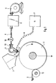
- a nozzle 4 is positioned in the area of the line of incidence of a melt film 2 emerging from a slot die 1 onto a cooling and take-off roller 3, the structure of which corresponds to an air knife designed according to aerodynamic aspects.
- the melt film 2 lying over more than half the circumference of the cooling roller 3 is detached from the cooling roller 3 in the region of a deflecting roller 12 and supplied to stretching devices (not shown).
- two electrodes 5, 5 'electrically insulated from the nozzle lips which are connected via a line 6, for example a high-voltage cable, to a high-frequency generator 7.
- the high-frequency generator 7 feeds the two electrodes 5, 5 'with a high-frequency alternating current of high voltage.
- a current of 0.1 to 2 amperes flows at the electrodes 5, 5 'at a voltage of 10 to 100 kV, preferably 2 to 20 kV, and a frequency of 3 to 100 kHz, preferably 8 to 32 kHz.
- the cooling roller 3 is at earth potential.
- the supply of the nozzle 4 with the amount of air or gas required for the application of the melt film takes place via a supply line 8, which can be a pipe or high-pressure hose line, from a blower 9.
- a shut-off valve 10 enables the desired or required blowing pressure in the nozzle 4 to be set.
- the nozzle 4 can also be used with gases, such as nitrogen or noble gases, from corresponding supply systems, e.g. Gas bottles, are charged.
- gases such as nitrogen or noble gases
- this procedural measure offers the possibility of specifically influencing the corona discharge process and thus of the application process, as well as of making targeted modifications to the melt film with regard to its surface topography and morphology.
- the second embodiment according to Fig. 1 comprises the ultrasonic atomizer 11, which is arranged between the fan 9 and the shut-off valve 10 in the supply line 8.
- the nozzle 4 is supplied with air by the blower 9, which is enriched with an aerosol, which is generated by ultrasonic atomization of a liquid in the ultrasonic atomizer 11.
- Two-substance atomizing nozzles are used as atomizers, in which the liquid passes through at ultrasonic speed escaping air is torn into tiny droplets, especially piezoelectric ultrasonic vibrators.
- the aerosol is bound by the electric field of the corona discharge only in the area of the two electrodes 5, 5 'and cannot stray into the environment.
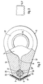
- FIG. 2 shows a cross section through a special embodiment of the nozzle 4, the structure of which largely corresponds to that of conventional air knives.
- the nozzle 4 consists essentially of an approximately cylindrical base body 15 which merges into two wedge-shaped nozzle lips 13, 13 '.
- a pressure compensation duct 14 into which air is blown axially via two pipe sockets 16 attached to the side windows 17.
- the pressure equalization channel 14 merges into a nozzle slot 18 enclosed by the nozzle lips 13, 13 '. This is interrupted in the area of the nozzle mouth by a bore 19 extending over the entire width of the nozzle, into which a rotatable rotary valve 20 is fitted.
- the rotary valve 20 in principle a cylindrical rod with a plurality of bores 21, 21 ′, 21 ⁇ distributed over its entire length and inclined to one another, stands over a coupling element which is guided to the outside through a bore, not shown, in one side disk 17, with a drive unit, eg a geared motor, in connection.
- the nozzle mouth is practically formed by the two high-voltage electrodes 5, 5 ', which are electrically shielded from the nozzle lips 13, 13' by insulators 22, 22 '.
- the course of the bores 21 ', 21' within the rotary valve 20 is indicated by dashed lines.
- the holes 21, 21 ', 21 ⁇ have the same or different diameters.
- the advantage of the nozzle 4 modified by the integrated rotary slide valve 20 is that the air or gas jet emerging from the nozzle slot 18 is divided into partial flows. Since, depending on the rotary movement of the rotary valve 20, constantly changing bores 21, 21 ', 21 ⁇ , ... are released, this results in a time and location-changing pressurization with air or gas of the melt film to be applied.
- This effect can be used in two ways in the sense of randomly influencing the thickness profile of the melt film.
- the locally different dynamic pressure of the individual partial flow causes local melt deformations and thus desired fluctuations in thickness, and on the other hand there are the morphological differences in the polymer film resulting from the varying cooling conditions are evident in the subsequent stretching processes, primarily in the transverse stretching. The latter occurs in particular when specific cooling conditions, such as enrichment of the blown air with aerosols, are set.
- Fig. 3 shows schematically a possible design of the two electrodes 5, 5 ', the discharge edges have the shape of sawtooth profiles. Of course, the discharge edges can be profiled like a knife.
- the method and the device are basically applicable for applying all common polymers that can be processed into flat films in the extrusion process, such as polyethylene terephthalate, polypropylene, polyethylene, polyamide etc.
Landscapes
- Engineering & Computer Science (AREA)
- Mechanical Engineering (AREA)
- Physics & Mathematics (AREA)
- Thermal Sciences (AREA)
- Extrusion Moulding Of Plastics Or The Like (AREA)
- Application Of Or Painting With Fluid Materials (AREA)
Claims (12)
- Procédé pour appliquer un film de matière plastique fondue sur une surface de refroidissement en mouvement, selon lequel un film de matière plastique fondue (2) est extrudé par une filière à fente large (1) sans inclusion d'air sur la surface de refroidissement et une pression est exercée sur la surface libre du film de matière fondue appliquée sur la surface de refroidissement par un courant de gaz ou d'air, caractérisé en ce que, dans la région de la ligne de dépose du film de matière plastique fondue sur la surface de refroidissement, on superpose au courant de gaz ou d'air une décharge corona produite par un courant alternatif à haute fréquence, et en ce que l'air ou le gaz auquel est superposée une décharge corona est enrichi par un aérosol qui est issu d'un liquide par une pulvérisation par ultrasons.
- Procédé selon la revendication 1, caractérisé en ce que le courant de gaz ou d'air est appliqué sur toute la largeur du film (2) de matière plastique fondue et en ce que le courant alternatif à haute fréquence utilisé pour la décharge corona est produit dans le voisinage immédiat de la fente de sortie d'une buse (4) débitant le courant de gaz ou d'air.
- Procédé selon les revendications 1 et 2, caractérisé en ce que le courant de gaz ou d'air est subdivisé en un certain nombre de courants qui "frappent" la surface libre du film (2) de matière plastique fondue avec des pressions dynamiques de différentes intensités.
- Procédé selon la revendication 3, caractérisé en ce que les courants de gaz ou d'air "frappent" la surface libre du film (2) de matière plastique fondue d'une façon intermittente aussi bien dans le temps que dans l'espace.
- Procédé selon les revendications 1 à 4, caractérisé en ce que l'air enrichi par un aérosol ou le gaz enrichi présente une température d'entre 2 et 95°C environ et en ce que la température est réglée par chauffage de l'air ou du gaz et/ou de l'aérosol.
- Procédé selon les revendications 1 à 5, caractérisé en ce que le courant de gaz ou d'air soufflé dans le champ électrique de tension alternative à haute fréquence est enrichi d'un aérosol de monomères, dispersions, solutions, de composants à bas et/ou haut poids moléculaire ou par des systèmes colloïdaux.
- Procédé selon une ou plusieurs des revendications 1 à 6, caractérisé en ce que l'électrode de haute tension (5, 5') est alimentée par un courant alternatif à haute fréquence d'une intensité de 0,1 à 2 A et d'une tension de 5 à 100 kV, notamment de 5 à 30 kV, et d'une fréquence de 3 à 100 kHz, notamment de 8 à 32 kHz.
- Dispositif pour appliquer un film (2) de matière plastique fondue sur un tambour de refroidissement tournant (3) comprenant une filière à fente large (1) servant à extruder le film de matière plastique fondue (2) sur le tambour de refroidissement (3) et une buse (4) à travers la fente de sortie de laquelle de l'air ou un gaz sort et "frappe" la surface libre du film (2) de matière plastique fondue, caractérisé en ce que la buse (4) est reliée par l'intermédiaire d'une vanne de réglage (10) à un ventilateur soufflant (9), en ce que le long des côtés extérieurs des lèvres de la buse (4) sont disposées des électrodes (5, 5') qui sont connectées à un générateur de haute fréquence (7) par une ligne (6) et en ce que, entre le ventilateur soufflant (9) et la vanne de réglage (10) est disposé, dans la conduite d'alimentation (8), un pulvérisateur à ultrasons (11) dans lequel on produit par pulvérisation d'un liquide un aérosol qui pénètre dans la buse (4).
- Dispositif selon la revendication 8, caractérisé en ce que les électrodes (5, 5') sont isolées électriquement des lèvres de la buse (4) et présentent la forme de lames.
- Dispositif selon la revendication 9, caractérisé en ce que les arêtes de décharge des deux électrodes (5, 5') présentent un profilage, notamment sous la forme d'un profil en dents de scie.
- Dispositif selon la revendication 8, caractérisé en ce que les deux lèvres (13, 13') de la buse (4) présentent un perçage (19) s'étendant sur toute la largeur de la buse et destiné à recevoir un obturateur tournant (20).
- Dispositif selon la revendication 11, caractérisé en ce que l'obturateur tournant (20) peut tourner dans le perçage (19) et présente un certain nombre de perçages (21, 21', 21") inclinés les uns par rapport aux autres qui présentent le même diamètre ou des diamètres différents.
Applications Claiming Priority (2)
| Application Number | Priority Date | Filing Date | Title |
|---|---|---|---|
| DE3729985 | 1987-09-08 | ||
| DE19873729985 DE3729985A1 (de) | 1987-09-08 | 1987-09-08 | Verfahren und vorrichtung zum anlegen eines films aus einer kunststoffschmelze an eine bewegte kuehlflaeche |
Publications (3)
| Publication Number | Publication Date |
|---|---|
| EP0306842A2 EP0306842A2 (fr) | 1989-03-15 |
| EP0306842A3 EP0306842A3 (en) | 1989-05-03 |
| EP0306842B1 true EP0306842B1 (fr) | 1993-02-24 |
Family
ID=6335444
Family Applications (1)
| Application Number | Title | Priority Date | Filing Date |
|---|---|---|---|
| EP88114307A Expired - Lifetime EP0306842B1 (fr) | 1987-09-08 | 1988-09-02 | Procédé et appareil pour appliquer une feuille en matière plastique fondue sur une surface de refroidissement en mouvement |
Country Status (2)
| Country | Link |
|---|---|
| EP (1) | EP0306842B1 (fr) |
| DE (2) | DE3729985A1 (fr) |
Families Citing this family (3)
| Publication number | Priority date | Publication date | Assignee | Title |
|---|---|---|---|---|
| DE9402027U1 (de) * | 1994-02-08 | 1995-06-14 | Wilkinson Sword Gmbh, 42659 Solingen | Vorrichtung zur Herstellung von Folien |
| DE19653749A1 (de) * | 1996-12-20 | 1998-06-25 | Hoechst Diafoil Gmbh | Vorrichtung zum Anlegen einer aus einer Breitschlitzdüse austretenden Folie an eine sich drehende Abzugswalze |
| CN109016580A (zh) * | 2018-08-20 | 2018-12-18 | 扬州市众和同盛包装材料有限公司 | 一种bopp触感丝光膜的制备工艺 |
Family Cites Families (3)
| Publication number | Priority date | Publication date | Assignee | Title |
|---|---|---|---|---|
| DE1504433C3 (de) * | 1961-04-20 | 1975-06-12 | Kalle Ag, 6202 Wiesbaden-Biebrich | Verfahren zum Herstellen von Polyolefin-Flachfolien |
| US3779682A (en) * | 1972-03-08 | 1973-12-18 | Du Pont | Quenching molten thermoplastic film |
| DE2460432C3 (de) * | 1974-12-20 | 1984-01-05 | Klaus 4803 Steinhagen Kalwar | Verfahren zum kontinuierlichen Herstellen einer Flachfolienbahn aus thermoplastischem Kunststoff oder von zwei- oder dreilagigen, bahnförmigen Verbundwerkstoffen und Vorrichtung zum Herstellen von zweilagigen, bahnförmigen Verbundwerkstoffen |
-
1987
- 1987-09-08 DE DE19873729985 patent/DE3729985A1/de not_active Withdrawn
-
1988
- 1988-09-02 EP EP88114307A patent/EP0306842B1/fr not_active Expired - Lifetime
- 1988-09-02 DE DE8888114307T patent/DE3878612D1/de not_active Expired - Fee Related
Also Published As
| Publication number | Publication date |
|---|---|
| DE3878612D1 (de) | 1993-04-01 |
| EP0306842A3 (en) | 1989-05-03 |
| EP0306842A2 (fr) | 1989-03-15 |
| DE3729985A1 (de) | 1989-03-16 |
Similar Documents
| Publication | Publication Date | Title |
|---|---|---|
| EP0279371A1 (fr) | Procédé et dispositif pour le prétraitement de surface de matériaux plastiques par une décharge corona électrique | |
| EP0355622A2 (fr) | Procédé et appareil pour le prétraitement de la surface d'une matière moulée mono- ou multicouche par décharge électrique corona | |
| DE1930987A1 (de) | Extrusionswerkzeug zum Herstellen von Mehrschichtblasfolien | |
| DD278986A5 (de) | Verfahren und vorrichtung zur bearbeitung von elastomerischen massen, insbesondere kunststoff, kautschuk und deren mischungen | |
| EP4121272B1 (fr) | Dispositif d'étirage et procédé d'étirage d'une feuille plastique dans le sens de transport de celle-ci | |
| EP1488910B1 (fr) | Appareil pour fabriquer un film thermoplastique | |
| EP0381044B1 (fr) | Procédé et dispositif pour prétraitement de surface d'objets plans par décharge corona électrique | |
| DE2535330A1 (de) | Verfahren und vorrichtung zum extrudieren und abschrecken einer polymeren folie | |
| DE2642685A1 (de) | Verfahren und vorrichtung zum vorbereiten eines dielektrischen substrates fuer ein beguenstigtes anhaften von kunststoff | |
| DE69524787T2 (de) | Verfahren und vorrichtung zur beschichtung eines metallbleches und daraus hergestelltes produkt | |
| DE2460432B2 (de) | Verfahren zum kontinuierlichen Herstellen einer Flachfolienbahn aus thermoplastischem Kunststoff oder von zwei- oder dreitägigen, bahnförmigen Verbundwerkstoffen und Vorrichtung zum Herstellen von zweitägigen, bahnförmigen Verbundwerkstoffen | |
| DE102019215492B4 (de) | Blasfolienanlage und Verfahren zur Herstellung von Folienschläuchen oder Folienbahnen | |
| EP0850747B1 (fr) | Dispositif pour l'application d'un film sortant d'une filière plate sur un tambour de tirage | |
| EP0920973B1 (fr) | Dispositif pour l'application d'un film sortant d'une filière plate sur un tambour de tirage | |
| DE69822127T2 (de) | Verbesserungen zum Herstellen van Vliesstoffen mit einem elektrostatischen geladenen Transportband | |
| EP0306842A2 (fr) | Procédé et appareil pour appliquer une feuille en matière plastique fondue sur une surface de refroidissement en mouvement | |
| DE10113089C1 (de) | Verfahren und Anlage zur Herstellung einer Folie aus thermoplastischem Kunststoff | |
| DE2162229A1 (de) | Verfahren und vorrichtung zur einspeisung von ausgangsstoffen in den scherspalt von maschinen zur herstellung von flaechigen kunststoffgebilden | |
| DE2732408A1 (de) | Verfahren und vorrichtung zum verbinden von zwei sich bewegenden bahnen | |
| DE69623948T2 (de) | Verbessertes verfahren zur herstellung einer dünnen folie aus einem flüssigkrystallinen polymer | |
| EP1744835B1 (fr) | Procede pour appliquer un film sur un substrat plat, element de renvoi et dispositif pour appliquer un film sur un substrat plat | |
| DE19617811C1 (de) | Vorrichtung zum Flachlegen eines Folienschlauches | |
| WO2023001664A2 (fr) | Dispositif d'étirage et procédé pour étirer une feuille plastique dans sa direction de transport | |
| DE10242174B4 (de) | Verfahren zur Herstellung selbstreinigender Folien im Blasverfahren | |
| EP0086977A1 (fr) | Procédé et dispositif pour le traitement de surface de feuilles continues au moyen de décharges électriques par effet de corona |
Legal Events
| Date | Code | Title | Description |
|---|---|---|---|
| PUAI | Public reference made under article 153(3) epc to a published international application that has entered the european phase |
Free format text: ORIGINAL CODE: 0009012 |
|
| AK | Designated contracting states |
Kind code of ref document: A2 Designated state(s): DE FR GB LU NL |
|
| PUAL | Search report despatched |
Free format text: ORIGINAL CODE: 0009013 |
|
| AK | Designated contracting states |
Kind code of ref document: A3 Designated state(s): DE FR GB LU NL |
|
| 17P | Request for examination filed |
Effective date: 19891004 |
|
| 17Q | First examination report despatched |
Effective date: 19910222 |
|
| GRAA | (expected) grant |
Free format text: ORIGINAL CODE: 0009210 |
|
| AK | Designated contracting states |
Kind code of ref document: B1 Designated state(s): DE FR GB LU NL |
|
| REF | Corresponds to: |
Ref document number: 3878612 Country of ref document: DE Date of ref document: 19930401 |
|
| ET | Fr: translation filed | ||
| GBT | Gb: translation of ep patent filed (gb section 77(6)(a)/1977) |
Effective date: 19930519 |
|
| EPTA | Lu: last paid annual fee | ||
| PLBE | No opposition filed within time limit |
Free format text: ORIGINAL CODE: 0009261 |
|
| STAA | Information on the status of an ep patent application or granted ep patent |
Free format text: STATUS: NO OPPOSITION FILED WITHIN TIME LIMIT |
|
| 26N | No opposition filed | ||
| PGFP | Annual fee paid to national office [announced via postgrant information from national office to epo] |
Ref country code: FR Payment date: 19950816 Year of fee payment: 8 |
|
| PGFP | Annual fee paid to national office [announced via postgrant information from national office to epo] |
Ref country code: GB Payment date: 19950821 Year of fee payment: 8 |
|
| PGFP | Annual fee paid to national office [announced via postgrant information from national office to epo] |
Ref country code: LU Payment date: 19950901 Year of fee payment: 8 |
|
| PG25 | Lapsed in a contracting state [announced via postgrant information from national office to epo] |
Ref country code: LU Free format text: LAPSE BECAUSE OF NON-PAYMENT OF DUE FEES Effective date: 19960902 Ref country code: GB Effective date: 19960902 |
|
| PG25 | Lapsed in a contracting state [announced via postgrant information from national office to epo] |
Ref country code: FR Effective date: 19960930 |
|
| NLS | Nl: assignments of ep-patents |
Owner name: CLAUDIA FLEMING |
|
| GBPC | Gb: european patent ceased through non-payment of renewal fee |
Effective date: 19960902 |
|
| REG | Reference to a national code |
Ref country code: FR Ref legal event code: ST |
|
| REG | Reference to a national code |
Ref country code: FR Ref legal event code: ST |
|
| REG | Reference to a national code |
Ref country code: FR Ref legal event code: TP |
|
| PGFP | Annual fee paid to national office [announced via postgrant information from national office to epo] |
Ref country code: NL Payment date: 19970930 Year of fee payment: 10 |
|
| PG25 | Lapsed in a contracting state [announced via postgrant information from national office to epo] |
Ref country code: NL Free format text: LAPSE BECAUSE OF NON-PAYMENT OF DUE FEES Effective date: 19990401 |
|
| NLV4 | Nl: lapsed or anulled due to non-payment of the annual fee |
Effective date: 19990401 |
|
| PGFP | Annual fee paid to national office [announced via postgrant information from national office to epo] |
Ref country code: DE Payment date: 19991130 Year of fee payment: 12 |
|
| PG25 | Lapsed in a contracting state [announced via postgrant information from national office to epo] |
Ref country code: DE Free format text: LAPSE BECAUSE OF NON-PAYMENT OF DUE FEES Effective date: 20010601 |