EP0306850A2 - Befestigungseinrichtung für die Radkappe oder ein Polrad zur Sensierung von Antiblockiersystemen auf der Radnabe eines Fahrzeugrades - Google Patents
Befestigungseinrichtung für die Radkappe oder ein Polrad zur Sensierung von Antiblockiersystemen auf der Radnabe eines Fahrzeugrades Download PDFInfo
- Publication number
- EP0306850A2 EP0306850A2 EP88114323A EP88114323A EP0306850A2 EP 0306850 A2 EP0306850 A2 EP 0306850A2 EP 88114323 A EP88114323 A EP 88114323A EP 88114323 A EP88114323 A EP 88114323A EP 0306850 A2 EP0306850 A2 EP 0306850A2
- Authority
- EP
- European Patent Office
- Prior art keywords
- wheel
- wheel hub
- circumferential groove
- cap
- hub
- Prior art date
- Legal status (The legal status is an assumption and is not a legal conclusion. Google has not performed a legal analysis and makes no representation as to the accuracy of the status listed.)
- Granted
Links
Images

Classifications
-
- B—PERFORMING OPERATIONS; TRANSPORTING
- B60—VEHICLES IN GENERAL
- B60B—VEHICLE WHEELS; CASTORS; AXLES FOR WHEELS OR CASTORS; INCREASING WHEEL ADHESION
- B60B27/00—Hubs
- B60B27/0047—Hubs characterised by functional integration of other elements
- B60B27/0068—Hubs characterised by functional integration of other elements the element being a sensor
-
- B—PERFORMING OPERATIONS; TRANSPORTING
- B60—VEHICLES IN GENERAL
- B60B—VEHICLE WHEELS; CASTORS; AXLES FOR WHEELS OR CASTORS; INCREASING WHEEL ADHESION
- B60B27/00—Hubs
- B60B27/001—Hubs with roller-bearings
-
- B—PERFORMING OPERATIONS; TRANSPORTING
- B60—VEHICLES IN GENERAL
- B60B—VEHICLE WHEELS; CASTORS; AXLES FOR WHEELS OR CASTORS; INCREASING WHEEL ADHESION
- B60B27/00—Hubs
- B60B27/02—Hubs adapted to be rotatably arranged on axle
-
- F—MECHANICAL ENGINEERING; LIGHTING; HEATING; WEAPONS; BLASTING
- F16—ENGINEERING ELEMENTS AND UNITS; GENERAL MEASURES FOR PRODUCING AND MAINTAINING EFFECTIVE FUNCTIONING OF MACHINES OR INSTALLATIONS; THERMAL INSULATION IN GENERAL
- F16C—SHAFTS; FLEXIBLE SHAFTS; ELEMENTS OR CRANKSHAFT MECHANISMS; ROTARY BODIES OTHER THAN GEARING ELEMENTS; BEARINGS
- F16C33/00—Parts of bearings; Special methods for making bearings or parts thereof
- F16C33/72—Sealings
- F16C33/723—Shaft end sealing means, e.g. cup-shaped caps or covers
-
- F—MECHANICAL ENGINEERING; LIGHTING; HEATING; WEAPONS; BLASTING
- F16—ENGINEERING ELEMENTS AND UNITS; GENERAL MEASURES FOR PRODUCING AND MAINTAINING EFFECTIVE FUNCTIONING OF MACHINES OR INSTALLATIONS; THERMAL INSULATION IN GENERAL
- F16C—SHAFTS; FLEXIBLE SHAFTS; ELEMENTS OR CRANKSHAFT MECHANISMS; ROTARY BODIES OTHER THAN GEARING ELEMENTS; BEARINGS
- F16C33/00—Parts of bearings; Special methods for making bearings or parts thereof
- F16C33/72—Sealings
- F16C33/76—Sealings of ball or roller bearings
- F16C33/78—Sealings of ball or roller bearings with a diaphragm, disc, or ring, with or without resilient members
- F16C33/7816—Details of the sealing or parts thereof, e.g. geometry, material
- F16C33/783—Details of the sealing or parts thereof, e.g. geometry, material of the mounting region
-
- F—MECHANICAL ENGINEERING; LIGHTING; HEATING; WEAPONS; BLASTING
- F16—ENGINEERING ELEMENTS AND UNITS; GENERAL MEASURES FOR PRODUCING AND MAINTAINING EFFECTIVE FUNCTIONING OF MACHINES OR INSTALLATIONS; THERMAL INSULATION IN GENERAL
- F16C—SHAFTS; FLEXIBLE SHAFTS; ELEMENTS OR CRANKSHAFT MECHANISMS; ROTARY BODIES OTHER THAN GEARING ELEMENTS; BEARINGS
- F16C41/00—Other accessories, e.g. devices integrated in the bearing not relating to the bearing function as such
- F16C41/007—Encoders, e.g. parts with a plurality of alternating magnetic poles
-
- F—MECHANICAL ENGINEERING; LIGHTING; HEATING; WEAPONS; BLASTING
- F16—ENGINEERING ELEMENTS AND UNITS; GENERAL MEASURES FOR PRODUCING AND MAINTAINING EFFECTIVE FUNCTIONING OF MACHINES OR INSTALLATIONS; THERMAL INSULATION IN GENERAL
- F16C—SHAFTS; FLEXIBLE SHAFTS; ELEMENTS OR CRANKSHAFT MECHANISMS; ROTARY BODIES OTHER THAN GEARING ELEMENTS; BEARINGS
- F16C43/00—Assembling bearings
- F16C43/04—Assembling rolling-contact bearings
- F16C43/045—Mounting or replacing seals
-
- G—PHYSICS
- G01—MEASURING; TESTING
- G01P—MEASURING LINEAR OR ANGULAR SPEED, ACCELERATION, DECELERATION, OR SHOCK; INDICATING PRESENCE, ABSENCE, OR DIRECTION, OF MOVEMENT
- G01P3/00—Measuring linear or angular speed; Measuring differences of linear or angular speeds
- G01P3/42—Devices characterised by the use of electric or magnetic means
- G01P3/44—Devices characterised by the use of electric or magnetic means for measuring angular speed
- G01P3/443—Devices characterised by the use of electric or magnetic means for measuring angular speed mounted in bearings
-
- F—MECHANICAL ENGINEERING; LIGHTING; HEATING; WEAPONS; BLASTING
- F16—ENGINEERING ELEMENTS AND UNITS; GENERAL MEASURES FOR PRODUCING AND MAINTAINING EFFECTIVE FUNCTIONING OF MACHINES OR INSTALLATIONS; THERMAL INSULATION IN GENERAL
- F16C—SHAFTS; FLEXIBLE SHAFTS; ELEMENTS OR CRANKSHAFT MECHANISMS; ROTARY BODIES OTHER THAN GEARING ELEMENTS; BEARINGS
- F16C19/00—Bearings with rolling contact, for exclusively rotary movement
- F16C19/54—Systems consisting of a plurality of bearings with rolling friction
- F16C19/541—Systems consisting of juxtaposed rolling bearings including at least one angular contact bearing
- F16C19/542—Systems consisting of juxtaposed rolling bearings including at least one angular contact bearing with two rolling bearings with angular contact
- F16C19/543—Systems consisting of juxtaposed rolling bearings including at least one angular contact bearing with two rolling bearings with angular contact in O-arrangement
-
- F—MECHANICAL ENGINEERING; LIGHTING; HEATING; WEAPONS; BLASTING
- F16—ENGINEERING ELEMENTS AND UNITS; GENERAL MEASURES FOR PRODUCING AND MAINTAINING EFFECTIVE FUNCTIONING OF MACHINES OR INSTALLATIONS; THERMAL INSULATION IN GENERAL
- F16C—SHAFTS; FLEXIBLE SHAFTS; ELEMENTS OR CRANKSHAFT MECHANISMS; ROTARY BODIES OTHER THAN GEARING ELEMENTS; BEARINGS
- F16C2226/00—Joining parts; Fastening; Assembling or mounting parts
- F16C2226/50—Positive connections
- F16C2226/70—Positive connections with complementary interlocking parts
- F16C2226/74—Positive connections with complementary interlocking parts with snap-fit, e.g. by clips
-
- F—MECHANICAL ENGINEERING; LIGHTING; HEATING; WEAPONS; BLASTING
- F16—ENGINEERING ELEMENTS AND UNITS; GENERAL MEASURES FOR PRODUCING AND MAINTAINING EFFECTIVE FUNCTIONING OF MACHINES OR INSTALLATIONS; THERMAL INSULATION IN GENERAL
- F16C—SHAFTS; FLEXIBLE SHAFTS; ELEMENTS OR CRANKSHAFT MECHANISMS; ROTARY BODIES OTHER THAN GEARING ELEMENTS; BEARINGS
- F16C2326/00—Articles relating to transporting
- F16C2326/01—Parts of vehicles in general
- F16C2326/02—Wheel hubs or castors
Definitions
- the invention relates to a fastening device for a hubcap or a magnet wheel for sensing anti-lock braking systems on the wheel hub of a vehicle wheel, in particular of trucks and their trailers.
- fastening devices of this type use flanges on the wheel cap and wheel hub, which are connected to one another by means of several screws. This solution is structurally complex. Assembly and disassembly are time consuming. In the case of oil-lubricated wheel bearings, special sealing measures must also be taken.
- Fastening devices of the type mentioned at the outset are also known, in which, for example, the wheel cap provided with an external thread is screwed into the internal thread on the wheel hub. Fluctuations in temperature, combined with the centrifugal forces that occur, can, however, lead to the unwanted loosening of a wheel cover fastened in this way. It is also difficult to dismantle if it e.g. by tightening when the wheel hub is warm. This type of attachment is also relatively expensive because of the thread.
- Magnetic wheels for sensing anti-lock braking systems are usually attached between the magnet wheel itself and the wheel hub by means of precise snug fits. This requires a high level of manufacturing precision. The fit is also no longer ensured if the wheel hub, as usual, already receives the fit provided for the pole wheel during its manufacture, but the brake should only be retrofitted with an anti-lock braking system after long use of the vehicle.
- the wheel hub has at its outer end portion a circumferential groove for receiving a sealing ring
- the wheel hub end portion of the wheel cover or the pole wheel has a circumferential groove facing the circumferential groove of the wheel hub, with which the end portion of the The wheel cap or the magnet wheel snaps over the sealing ring in the circumferential groove of the wheel hub by being axially pushed on.
- the wheel cap or the magnet wheel required for an anti-lock braking system is simply pressed onto the wheel hub.
- the sealing ring which snaps into the circumferential grooves which are assigned to one another, the two components are held securely but nevertheless easily assembled and disassembled to one another.
- the wheel cap or the magnet wheel preferably lies in the snapped-on position with its end face on the wheel hub side against a shoulder of the wheel hub. This additionally stabilizes the seat of the hubcap or the pole wheel on the wheel hub.
- flats or slots for engagement with a tool such as a screwdriver can be provided in the border area between the end face and the shoulder, which makes it easier to remove the wheel cap or the magnet wheel.
- the circumferential groove in which the sealing ring is to be received permanently that is to say either the circumferential groove of the wheel hub or the circumferential groove of the wheel cover or the pole wheel preferably have a groove base which is essentially symmetrical with respect to the groove center plane.
- the circumferential groove in which the The sealing ring should only snap into place when the wheel cap or the pole wheel is pushed onto the wheel hub i.e. the axial outer flank of the relevant circumferential groove is flatter and lower than the axially inner flank either in the circumferential groove of the wheel cap or the pole wheel or the circumferential groove of the wheel hub. This ensures that the hubcap or the magnet wheel can be brought more easily into the snap-in position in which the sealing ring lies in both circumferential grooves and seals the two parts against one another.
- the wheel cap or the magnet wheel preferably overlaps the end section of the wheel hub. This permits particularly simple assembly and disassembly and, in the case of the wheel cap, additional covering of the wheel hub interior against the ingress of dirt. Conversely, it is also possible for the wheel cap or the magnet wheel to engage in the end section of the wheel hub. Therefore, the designs of the wheel hub on the one hand and the wheel cover or pole wheel on the other hand, in their end regions, to ensure snapping on, can be readily redesigned or interchanged with one another in order to prevent the wheel cover or the pole wheel from overlapping Wheel hub to engage the wheel cap or the magnet wheel in the wheel hub.
- the inner surface of the end section of the wheel cap or the pole wheel preferably extends from the inner circumferential groove to the end face at a small opening angle, for example approximately 15 °, obliquely outwards to the axial direction.
- the diameter of the insertion opening of the wheel cover or the magnet wheel is thus somewhat larger than the outer diameter of the sealing ring on the wheel hub onto which the wheel cover or the magnet wheel is to be attached.
- the respective axially outer flank of one or the other circumferential groove is flatter and lower than the axially inner flank, it is particularly advantageous for a tight but nevertheless easily detachable fit of the wheel cap or the magnet wheel on the end section, if necessary the wheel hub when the axially outer flank extends at an angle between approximately 15 and 45 ° to the axial direction.
- the axially inner flank extends, for example, at an angle between approximately 15 and 45 °, preferably approximately 30 °, to the radial direction, while the two flanks of the circumferential grooves can be at an angle between approximately 60 and 120 °.
- the brake drum 18 and the wheel 19 are screwed tight via an outer flange.
- a wheel cap 1 and, on the other hand, a magnet wheel 2 are held, each with a fastening device according to the invention.
- the wheel cap 1 has an edge flange which is angled approximately perpendicularly from the cap base.
- a circumferential groove 8 is arranged in the inner surface of the wheel hub-side end sections 7 of the edge flange of the wheel cap 1 and of the magnet wheel 2.
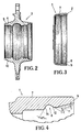
- the circumferential groove 5 which is provided on one side only in this example has a groove base which is essentially symmetrical with respect to the center plane of the groove.
- the sealing ring 6 is permanently received in the circumferential groove 5.
- the end section 4 widens to approximately conical to the wheel hub center plane. Either a hub cap or a magnet wheel can be placed on it.
- FIG. 3 illustrates a wheel cap 1 which is to be fixed on a wheel hub 3 according to FIG. 2 of the fastening device according to the invention.
- the wheel cap 1 has on the inner surface of its end section 7 a circumferential groove 8, the axially outer flank 12 of which forms an angle of, for example, 30 ° to the axial direction, while the axially inner flank 14 is steeper and at an angle of, for example, 30 ° to the radial direction.
- the axially outer flank 12 is also designed to be lower than the axially inner flank 14.
- the wheel cap 1 with its end section 7 can be easily brought across the end section 4 of the wheel hub 3 into a position in which the circumferential groove 5 is located in the circumferential groove 5
- Wheel hub 3 located sealing ring 6 snaps into the inner circumferential groove 8 of the wheel cap 1, so that the wheel cap 1 is held securely but releasably on the wheel hub 3.
- the wheel cap 1 overlaps the end section 4 of the wheel hub 3 with its end section 7.
- the placement of the wheel cap 1 on the end section 4 of the wheel hub 3 is facilitated in that the inner surface 11 of the end section 7 of the wheel cap 1 extends from the inner circumferential groove 8 to the end face 9 at a small opening angle of, for example, 15 ° to the axial direction extends obliquely outwards, so that the diameter of the insertion
- the opening of the wheel cap 1 is slightly larger than the end diameter of the end portion 4 of the wheel hub 3 and possibly slightly larger than the outer diameter of the sealing ring 6 and the inner surface 11 acts as a run-on slope for the sealing ring 6 until it snaps into the groove 8.
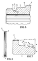
- FIG. 5 illustrates another embodiment of the end section 4 of the wheel hub 3 for snapping on a wheel cap 1 or a pole wheel 2 intended for anti-lock braking systems according to FIG. 6.
- the outer circumferential groove 5 of the end section 4 is in the manner asymmetrical that the axially outer flank 13 is mirror-symmetrical at approximately the same angle as the radially inner flank 15 to the radial direction, but the flank 13 is lower than the flank 15, so that the sealing ring can easily snap into the circumferential groove 5 if it is from is pushed on axially outside.
- the flanks 13 and 15 form an angle of approximately 60 ° between them in this example.
- the end section 7 of the magnet wheel 2 according to FIG. 6 is designed in detail in accordance with FIG. 7.
- This end section 7 is similar to the end section 7 of the wheel cap 1 of FIG. 4, but the axially outer flank 12 does not run as flat as the outer flank of FIG. 4, namely in this example at an angle of approximately 45 ° to the axial direction. This further improves the tight fit of the pole ring 2 on the wheel hub 3 according to FIG. 5.
Landscapes
- Engineering & Computer Science (AREA)
- General Engineering & Computer Science (AREA)
- Mechanical Engineering (AREA)
- Physics & Mathematics (AREA)
- General Physics & Mathematics (AREA)
- Rolling Contact Bearings (AREA)
- Regulating Braking Force (AREA)
- Transmission And Conversion Of Sensor Element Output (AREA)
Abstract
Description
- Die Erfindung bezieht sich auf eine Befestigungseinrichtung für eine Radkappe oder einen Polrad zur Sensierung von Antiblockiersystemen auf der Radnabe eines Fahrzeugrades, insbesondere von Lastkraftfahrzeugen und deren Anhänger.
- Bei bekannten Befestigungseinrichtungen dieser Art werden Flansche an Radkappe und Radnabe verwendet, die über mehrere Schrauben miteinander verbunden werden. Diese Lösung ist konstruktiv aufwendig. Montage und Demontage sind zeitraubend. Bei ölgeschmierten Radlagern müssen ferner besondere Maßnahmen zur Abdichtung getroffen werden. Es sind auch Befestigungseinrichtungen der eingangs genannten Art bekannt, bei welchen bspw. die mit einem Außengewinde versehene Radkappe in das Innengewinde an der Radnabe eingeschraubt wird. Temperaturschwankungen, kombiniert mit den auftretenden Fliehkräften, können jedoch zum ungewollten Lösen einer so befestigten Radkappe führen. Sie ist außerdem schwer demontierbar wenn sie, z.B. durch Anziehen im warmen Zustand der Radnabe, festsitzt. Diese Befestigungsart ist ebenfalls wegen des Gewindes verhältnismäßig kostspielig.
- Polräder zur Sensierung von Antiblockiersystemen werden üblicherweise über genaue Paßsitze zwischen dem Polrad selbst und der Radnabe befestigt. Das bedingt eine hohe Fertigungspräzision. Der Paßsitz ist ferner nicht mehr sichergestellt, wenn die Radnabe, wie üblich, bereits bei ihrer Herstellung den für das Polrad vorgesehenen Paßsitz erhält, die Bremse aber erst nach längerer Benutzung des Fahrzeuges mit einem Antiblockiersystem nachgerüstet werden soll.
- Hiervon ausgehend ist es Aufgabe der vorliegenden Erfindung eine Befestigungseinrichtung der gattungsgemäßen Art vorzuschlagen, die mit niedrigen Kosten herstellbar ist, bei welcher trotz schneller sowie leichter Montage und Demontage ein selbsttätiges Lösen der Radkappe bzw. des Polrades von der Radnabe verhindert und eine Abdichtung vornehmlich zwischen Radkappe und Radnabe erreicht wird.
- Diese Aufgabe wird erfindungsgemäß im wesentlichen dadurch gelöst, daß die Radnabe an ihrem äußeren Endabschnitt eine Umfangsnut für die Aufnahme eines Dichtringes aufweist, und daß der radnabenseitige Endabschnitt der Radkappe bzw. des Polrades eine der Umfangsnut der Radnabe zugekehrte Umfangsnut aufweist, mit welcher der Endabschnitt der Radkappe bzw. des Polrades über den Dichtungsring in der Umfangsnut der Radnabe durch axiales Aufschieben schnappt. Bei dieser konstruktiv einfachen Lösung wird die Radkappe bzw. das für ein Antiblockiersystem notwendige Polrad einfach auf die Radnabe aufgedrückt. Mit Hilfe der in den einander zugeordneten Umfangsnuten einschnappenden Dichtungsringes werden die beiden Bauteile sicher aber dennoch leicht montierbar und demontierbar aneinander dichtend gehalten.
- Vorzugsweise liegt die Radkappe bzw. das Polrad in der aufgeschnappten Lage mit ihrer bzw. seiner radnabenseitigen Stirnfläche an einer Schulter der Radnabe an. Hierdurch wird der Sitz der Radkappe bzw. des Polrades an der Radnabe zusätzlich stabilisiert. Zum Lösen der Radkappe bzw. des Polrades von der Radnabe können im Grenzbereich zwischen Stirnfläche und Schulter Abflachungen bzw. Schlitze zum Eingriff mit einem Werkzeug wie bspw. einem Schraubenzieher, vorhanden sein, wodurch das Demontieren der Radkappe bzw. des Polrades erleichtert wird.
- Diejenige Umfangsnut, in welcher der Dichtungsring dauerhaft aufgenommen werden soll, also entweder die Umfangsnut der Radnabe oder die Umfangsnut der Radkappe bzw. des Polrades weisen vorzugsweise einen im wesentlichen zur Nutmittenebene symmetrischen Nutgrund auf. Insbesondere in diesem Fall ist es von Vorteil, wenn bei derjenigen Umfangsnut, in welcher der Dichtungsring erst beim Aufschieben der Radkappe bzw. des Polrades auf die Radnabe einschnappen soll, also entweder bei der Umfangsnut der Radkappe bzw. des Polrades oder der Umfangsnut der Radnabe die axial äußere Flanke der betreffenden Umfangsnut flacher und niedriger ausgestaltet ist als die axial innere Flanke. Hierdurch wird erreicht, daß man die Radkappe bzw. das Polrad leichter in die Einschnapplage bringen kann, in welcher der Dichtungsring in beiden Umfangsnuten liegt und die beiden Teile gegeneinander abdichtet.
- Vorzugsweise übergreift die Radkappe bzw. das Polrad den Endabschnitt der Radnabe. Dies erlaubt eine besonders einfache Montage und Demontage und bei der Radkappe eine zusätzliche Abdeckung des Radnabeninnenraumes gegen Eindringen von Schmutz. Es ist aber auch umgekehrt möglich, daß die Radkappe bzw. das Polrad in den Endabschnitt der Radnabe eingreift. Deswegen können die zuvor und nachfolgend geschilderten Ausgestaltungen von Radnabe einerseits und Radkappe bzw. Polrad andererseits in ihren Endbereichen, um das Aufschnappen zu gewährleisten, ohne weiteres entsprechend umgestaltet bzw. gegeneinander vertauscht zu werden, um von einem Übergreifen der Radkappe bzw. des Polrades über die Radnabe zu einem Eingreifen der Radkappe bzw. des Polrades in die Radnabe überzugehen.
- Die Innenfläche des Endabschnitts der Radkappe bzw. des Polrades verläuft vorzugsweise von der inneren Umfangsnut aus bis zur Stirnfläche unter einem geringen Öffnungswinkel, von z.B. etwa 15°, zur Axialrichtung schräg nach außen. Der Durchmesser der Einführungsöffnung der Radkappe bzw. des Polrades sind dadurch etwas größer als der Außendurchmesser des Dichtungsringes auf der Radnabe, auf welche die Radkappe bzw. das Polrad aufgesteckt werden soll.
- Für den Fall, daß die jeweils axial äußere Flanke der einen oder anderen Umfangsnut flacher und niedriger ausgestaltet ist als die axial innere Flanke, ist es von besonderem Vorteil für einen straffen aber dennoch bei Bedarf leicht lösbaren Sitz der Radkappe bzw. des Polrades auf dem Endabschnitt der Radnabe, wenn die axial äußere Flanke unter einem Winkel zwischen etwa 15 und 45° zur Axialrichtung verläuft.
- Die axial innere Flanke verläuft dabei beispielsweise unter einem Winkel zwischen etwa 15 und 45°, vorzugsweise von etwa 30°, zur Radialrichtung, während die beiden Flanken der Umfangsnuten in einem Winkel zwischen etwa 60 und 120° stehen können.
- Weitere Ziele, Merkmale, Vorteile und Anwendungsmöglichkeiten der vorliegenden Erfindung ergeben sich aus der nachfolgenden Beschreibung von Ausführungsbeispielen anhand der Zeichnung. Dabei bilden alle beschriebenen und/oder bildlich dargestellten Merkmale für sich oder in beliebiger sinnvoller Kombination den Gegenstand der vorliegenden Erfindung, auch unabhängig von ihrer Zusammenfassung in den Ansprüchen oder deren Rückbeziehung.
- Es zeigt:
- Fig. 1 schematisch im Schnitt (zur oberen Hälfte weggebrochen) eine die Erfindung aufweisende Befestigungseinrichtung für eine Radkappe und für ein Polrad an einer Radnabe,
- Fig. 2 schematisch im Schnitt eine andere Ausführungsform einer für die Verwendung bei der erfindungsgemäßen Befestigungseinrichtung in ihrem axial äußeren Endbereich entsprechend ausgebildete Radnabe,
- Fig. 3 schematisch im Schnitt eine für die Verwendung bei einer erfindungsgemäßen Befestigungseinrichtung, z.B. im Zusammenwirken mit einer Radnabe gemäß Fig. 2 zu verwendende Radkappe,
- Fig. 4 eine vergrößerte Darstellung des Ausschnittes Z von Fig. 3 im Bereich eines radnabenseitigen Endabschnittes der Radkappe,
- Fig. 5 eine vergrößerte Schnittdarstellung des axial äußeren Endabschnittes einer für die erfindungsgemäße Befestigungseinrichtung bestimmten Radnabe,
- Fig. 6 demgegenüber verkleinert im Schnitt ein Polrad zur Verwendung mit einer Radnabe gemäß Fig. 5, und
- Fig. 7 eine vergrößerte Schnittdarstellung des Ausschnitts Y des Polrad gemäß Fig. 6.
- An der Radnabe 3 gemäß Fig. 1, welche mittels mindestens eines Radlagers 16 auf dem Achszapfen einer Radachse 17 drehbar gelagert ist, sind über einen äußeren Flansch die Bremstrommel 18 und das Rad 19 festgeschraubt. Auf den verjüngten äußeren Endabschnitten der Radnabe 3 ist einerseits eine Radkappe 1 andererseits ein Polrad 2 mit je einer erfindungsgemäßen Befestigungseinrichtung gehalten. Zu diesem Zweck hat die Radkappe 1 einen etwa senkrecht von dem Kappenboden abgewinkelten Randflansch. In der Innenfläche der radnabenseitigen Endabschnitte 7 von dem Randflansch der Radkappe 1 und des Polrades 2 ist je eine Umfangsnut 8 angeordnet. In der Außenfläche der Endabschnitte der Radnabe 4 befindet sich je eine Umfangsnut 5, in welcher je ein Dichtungsring 6 aufgenommen ist. In der Darstellung von Fig. 1 sind die Radkappe 1 und das Polrad 2 mit ihren Endabschnitten 7 so auf den Endabschnitten 4 der Radnabe 3 aufgeschnappt, daß die Dichtungsringe 6 sowohl in der Umfangsnuten 5 als auch in den Umfangsnuten 8 liegen.
- In diesem aufgeschnappten Zustand liegen die Radkappe 1 und das Polrad 2 mit den Stirnflächen 9 ihrer Endabschnitte 7 an je einer äußeren Ringschulter 10 der Endabschnitte 4 der Radnabe 3 an.
- Bei der Ausführungsform der Radnabe von Fig. 2 hat die in diesem Beispiel nur einseitig vorgesehene Umfangsnut 5 einen im wesentlichen zur Nutmittenebene symmetrischen Nutgrund. In der Umfangsnut 5 wird der Dichtungsring 6 dauerhaft aufgenommen. Der Endabschnitt 4 verbreitert sich zur Radnabenmittenebene zu etwa konisch. Auf ihn kann entweder eine Radkappe oder ein Polrad aufgesetzt werden.
- Fig. 3 veranschaulicht eine Radkappe 1, die auf einer Radnabe 3 gemäß Fig. 2 der erfindungsgemäßen Befestigungseinrichtung festgelegt werden soll. Wie insbesondere aus der vergrößerten Darstellung von Fig. 4 ersichtlich, hat die Radkappe 1 auf der Innenfläche ihres Endabschnittes 7 eine Umfangsnut 8, deren axial äußere Flanke 12 einen Winkel von z.B. 30° zur Axialrichtung bildet, während die axial innere Flanke 14 steiler verläuft und zwar unter einem Winkel von z.B. 30° zur Radialrichtung. Die axial äußere Flanke 12 ist außerdem niedriger ausgebildet als die axial innere Flanke 14. Auf diese Weise kann die Radkappe 1 mit ihrem Endabschnitt 7 den Endabschnitt 4 der Radnabe 3 übergreifend leicht in eine Stellung gebracht werden, in welcher der sich in der Umfangsnut 5 der Radnabe 3 befindliche Dichtungsring 6 in die innere Umfangsnut 8 der Radkappe 1 einschnappt, so daß die Radkappe 1 sicher aber lösbar an der Radnabe 3 gehalten wird. In dieser Lage übergreift die Radkappe 1 den Endabschnitt 4 der Radnabe 3 mit ihrem Endabschnitt 7. Das Aufsetzen der Radkappe 1 auf den Endabschnitt 4 der Radnabe 3 wird dadurch erleichtert, daß die Innenfläche 11 des Endabschnitts 7 der Radkappe 1 von der inneren Umfangsnut 8 aus bis zur Stirnfläche 9 unter einem geringen Öffnungswinkel von z.B. 15° zur Axialrichtung schräg nach außen verläuft, so daß der Durchmesser der Einführungs öffnung der Radkappe 1 geringfügig größer ist als der stirnseitige Durchmesser des Endabschnitts 4 der Radnabe 3 und ggf. geringfügig größer als der Außendurchmesser des Dichtungsringes 6 und die Innenfläche 11 als Auflaufschräge für den Dichtungsring 6 wirkt, bis dieser in die Nut 8 einschnappt.
- Fig. 5 veranschaulicht eine andere Ausgestaltung des Endabschnittes 4 der Radnabe 3 für das Aufschnappen einer Radkappe 1 bzw. einer für Antiblockiersysteme bestimmten Polrades 2 gemäß Fig. 6. Bei der Ausgestaltung gemäß Fig. 5 ist die äußere Umfangsnut 5 des Endabschnittes 4 in der Weise unsymmetrisch, daß die axial äußere Flanke 13 zwar spiegelsymmetrisch im etwa gleichem Winkel wie die radial innere Flanke 15 zur Radialrichtung verläuft, die Flanke 13 jedoch niedriger ist als die Flanke 15, so daß der Dichtungsring leicht in die Umfangsnut 5 einschnappen kann, wenn er von axial außen aufgeschoben wird. Die Flanken 13 und 15 bilden zwischen sich in diesem Beispiel einen Winkel von etwa 60°. Der Endabschnitt 7 des Polrades 2 gemäß Fig. 6 ist im einzelnen entsprechend der Fig. 7 ausgebildet. Dieser Endabschnitt 7 ist ähnlich dem Endabschnitt 7 der Radkappe 1 von Fig. 4, wobei die axial äußere Flanke 12 jedoch nicht so flach verläuft wie die äußere Flanke von Fig. 4, nämlich in diesem Beispiel unter einem Winkel von etwa 45° zur Axialrichtung. Hierdurch wird der feste Sitz des Polrings 2 auf der Radnabe 3 gemäß Fig. 5 noch verbessert.
-
- 1 Radkappe
- 2 Polrad
- 3 Radnabe
- 4 äußerer Endabschnitt
- 5 Umfangsnut
- 6 Dichtungsring
- 7 radnabenseitiger Endabschnitt
- 8 Umfangsnut
- 9 Stirnfläche
- 10 Schulter
- 11 Innenfläche
- 12 äußere Flanke
- 13 äußere Flanke
- 14 innere Flanke
- 15 innere Flanke
- 16 Radlager
- 17 Radachse
- 18 Bremstrommel
- 19 Rad
Claims (9)
Priority Applications (1)
| Application Number | Priority Date | Filing Date | Title |
|---|---|---|---|
| AT88114323T ATE86187T1 (de) | 1987-09-09 | 1988-09-02 | Befestigungseinrichtung fuer die radkappe oder ein polrad zur sensierung von antiblockiersystemen auf der radnabe eines fahrzeugrades. |
Applications Claiming Priority (2)
| Application Number | Priority Date | Filing Date | Title |
|---|---|---|---|
| DE3730184 | 1987-09-09 | ||
| DE19873730184 DE3730184A1 (de) | 1987-09-09 | 1987-09-09 | Befestigungseinrichtung fuer die radkappe oder ein polrad zur sensierung von antiblockiersystemen auf der radnabe eines fahrzeugrades |
Publications (3)
| Publication Number | Publication Date |
|---|---|
| EP0306850A2 true EP0306850A2 (de) | 1989-03-15 |
| EP0306850A3 EP0306850A3 (en) | 1990-02-28 |
| EP0306850B1 EP0306850B1 (de) | 1993-03-03 |
Family
ID=6335560
Family Applications (1)
| Application Number | Title | Priority Date | Filing Date |
|---|---|---|---|
| EP88114323A Expired - Lifetime EP0306850B1 (de) | 1987-09-09 | 1988-09-02 | Befestigungseinrichtung für die Radkappe oder ein Polrad zur Sensierung von Antiblockiersystemen auf der Radnabe eines Fahrzeugrades |
Country Status (5)
| Country | Link |
|---|---|
| US (1) | US4932725A (de) |
| EP (1) | EP0306850B1 (de) |
| AT (1) | ATE86187T1 (de) |
| DE (3) | DE3730184A1 (de) |
| ES (1) | ES2040301T3 (de) |
Cited By (2)
| Publication number | Priority date | Publication date | Assignee | Title |
|---|---|---|---|---|
| EP0694421A2 (de) | 1994-07-30 | 1996-01-31 | Ford-Werke Aktiengesellschaft | Befestigung eines Ringbauteiles auf einem Nabenbauteil |
| EP0751311A1 (de) * | 1995-03-16 | 1997-01-02 | Nsk Ltd | Wälzlagereinheit mit Drehgeschwindigkeitssensor |
Families Citing this family (11)
| Publication number | Priority date | Publication date | Assignee | Title |
|---|---|---|---|---|
| IT217181Z2 (it) * | 1989-09-12 | 1991-11-12 | Iveco Fiat | Gruppo di collegamento di una ruotaad un asse di un veicolo |
| IT1233900B (it) * | 1989-09-28 | 1992-04-21 | Riv Officine Di Villar Perosa | Ruota fonica per il rilevamento della velocita' di un organo rotante, rivestita di materiale elastomerico |
| IT217199Z2 (it) * | 1989-09-28 | 1991-11-12 | Riv Officine Di Villar Perosa | Anello magnetico polarizzato per ilrilevamento della velocita di un organo rotante dotato di manicotto diprotezione |
| DE4007797C1 (en) * | 1990-03-12 | 1991-05-02 | Mercedes-Benz Aktiengesellschaft, 7000 Stuttgart, De | Circular coil fastener for attachment to motor vehicle - connects to pressure sensor for contactless transmission of tyre pressure signals |
| DE4201328A1 (de) * | 1992-01-20 | 1993-07-22 | Teves Metallwaren Alfred | Sensor |
| GB9214639D0 (en) * | 1992-07-09 | 1992-08-19 | Timken Co | Bearings |
| JP3100153U (ja) * | 2003-08-29 | 2004-04-30 | 株式会社 ジャパン アクティブ | 概略円板形状のキャップ及び前記キャップを有するホイール |
| DE102005056063B4 (de) * | 2005-11-24 | 2019-06-06 | Knorr-Bremse Systeme für Nutzfahrzeuge GmbH | An einer Radnabe befestigbare Bremsscheibe |
| DE102006026451B3 (de) * | 2006-06-07 | 2008-03-13 | Knorr-Bremse Systeme für Nutzfahrzeuge GmbH | An einer Radnabe eines Fahrzeuges befestigbare Bremsscheibe |
| DE102013016275A1 (de) * | 2013-09-28 | 2015-04-02 | GM Global Technology Operations LLC (n. d. Ges. d. Staates Delaware) | Radkappe mit integrierter Hülse als Radnabenschutz |
| IT201800010494A1 (it) * | 2018-11-22 | 2020-05-22 | Skf Ab | Gruppo mozzo ruota con dispositivo di amplificazione di un segnale magnetico |
Family Cites Families (11)
| Publication number | Priority date | Publication date | Assignee | Title |
|---|---|---|---|---|
| DE666703C (de) * | 1935-12-18 | 1938-10-26 | Eisenwerke Akt Ges Deutsche | Deckelverschluss fuer Radnaben aller Art |
| GB1169751A (en) * | 1966-01-21 | 1969-11-05 | Dunlop Co Ltd | Improvements in or relating to Speed-Sensing Devices, particularly for Vehicle Anti-Skid Braking Systems |
| CH470771A (de) * | 1967-09-15 | 1969-03-31 | Interelectric Ag | Kommutator für Kleinstmotoren und Verfahren zum Herstellen desselben |
| US3598450A (en) * | 1969-08-28 | 1971-08-10 | Superior Industries | Vehicle wheel and wheel cap assembly |
| US4067621A (en) * | 1976-01-20 | 1978-01-10 | W. R. Grace & Co. | Plastic hub cap |
| JPS5826164Y2 (ja) * | 1977-11-01 | 1983-06-06 | トヨタ自動車株式会社 | センタキャップ又はホイ−ルキャップの取付構造 |
| US4602705A (en) * | 1981-11-09 | 1986-07-29 | Lucas Industries Public Limited Company | Flywheel mechanism for anti-skid braking systems |
| US4453698A (en) * | 1982-04-29 | 1984-06-12 | Allegheny Valve Company | Stuffing box with O-ring detent for control mechanism of emergency valve |
| US4544167A (en) * | 1982-06-11 | 1985-10-01 | Texas Turbine, Inc. | Face seal with resilient packing ring forcing face rings together |
| JPH035165Y2 (de) * | 1985-04-05 | 1991-02-08 | ||
| DE8534939U1 (de) * | 1985-12-12 | 1986-02-20 | Wipperfürth, Dieter, 6800 Mannheim | Diebstahlgesicherte bzw. diebstahlgeschützte Radeinheit |
-
1987
- 1987-09-09 DE DE19873730184 patent/DE3730184A1/de not_active Withdrawn
- 1987-09-09 DE DE8717786U patent/DE8717786U1/de not_active Expired - Lifetime
-
1988
- 1988-09-02 DE DE8888114323T patent/DE3878795D1/de not_active Expired - Lifetime
- 1988-09-02 ES ES198888114323T patent/ES2040301T3/es not_active Expired - Lifetime
- 1988-09-02 AT AT88114323T patent/ATE86187T1/de active
- 1988-09-02 EP EP88114323A patent/EP0306850B1/de not_active Expired - Lifetime
- 1988-09-09 US US07/242,411 patent/US4932725A/en not_active Expired - Lifetime
Cited By (3)
| Publication number | Priority date | Publication date | Assignee | Title |
|---|---|---|---|---|
| EP0694421A2 (de) | 1994-07-30 | 1996-01-31 | Ford-Werke Aktiengesellschaft | Befestigung eines Ringbauteiles auf einem Nabenbauteil |
| EP0694421A3 (de) * | 1994-07-30 | 1997-03-26 | Ford Werke Ag | Befestigung eines Ringbauteiles auf einem Nabenbauteil |
| EP0751311A1 (de) * | 1995-03-16 | 1997-01-02 | Nsk Ltd | Wälzlagereinheit mit Drehgeschwindigkeitssensor |
Also Published As
| Publication number | Publication date |
|---|---|
| US4932725A (en) | 1990-06-12 |
| EP0306850B1 (de) | 1993-03-03 |
| ATE86187T1 (de) | 1993-03-15 |
| DE3730184A1 (de) | 1989-03-23 |
| DE3878795D1 (de) | 1993-04-08 |
| ES2040301T3 (es) | 1993-10-16 |
| DE8717786U1 (de) | 1990-06-13 |
| EP0306850A3 (en) | 1990-02-28 |
Similar Documents
| Publication | Publication Date | Title |
|---|---|---|
| DE69303076T2 (de) | Lagereinheit für ein Fahrzeugrad | |
| EP3215750B1 (de) | Sicherungselement und sicherungssystem | |
| DE3914175C2 (de) | ||
| EP2606252B1 (de) | Bremsenabdeckblech | |
| EP0306850A2 (de) | Befestigungseinrichtung für die Radkappe oder ein Polrad zur Sensierung von Antiblockiersystemen auf der Radnabe eines Fahrzeugrades | |
| DE20010377U1 (de) | System zur Verbindung eines Anlasserzahnkranzes mit einem der Ausgangswelle eines Verbrennungsmotors verbundenen Träger | |
| EP2481942A1 (de) | Spannvorrichtung zur Befestigung einer Hohlwelle oder Nabe auf einer Welle | |
| WO2012159779A1 (de) | Wälzlageranordnung mit formschluss unterstützendem verspannungsmittel | |
| DE2430609A1 (de) | Radlagerung | |
| EP0617208A1 (de) | Anordnung zur Lagerung einer Welle oder Achse in einem Tragteil | |
| EP3447321B1 (de) | Mit einem gleichlaufgelenk verbundene radnaben-wälzlageranordnung für ein kraftfahrzeug mit einer dichtungsvorrichtung | |
| DE102015212067A1 (de) | Wälzlagereinheit | |
| EP3061916A1 (de) | Radscheibenanordnung eines Rotors und Verfahren zur Montage einer Radscheibenanordnung eines Rotors | |
| WO2009109162A2 (de) | Teilelement für ein dichtelement eines lagers | |
| DE102013213514A1 (de) | Sicherungsvorrichtung zum Sichern einer Mutter gegen ungewolltes Losdrehen, sowie Lageranordnung einer Welle | |
| DE102014200665A1 (de) | Kegelrollenlager und Verfahren zur Montage eines Kegelrollenlagers | |
| DE4419198A1 (de) | Kraftfahrzeugrad, insbesondere für Personenkraftfahrzeuge | |
| DE19836239C2 (de) | Fahrzeugrad | |
| DE102019208977B4 (de) | Radlagersicherungselement | |
| DE102009059844A1 (de) | Radnabe mit getriebeseitigem Schraubenanschlag | |
| DE102017200411A1 (de) | Befestigungsanordnung zur Befestigung mindestens eines Bauteils auf einer Welle | |
| DE10109660A1 (de) | Sicherungsring und Befestigungsvorrichtung für eine Welle-Nabe-Verbindung | |
| DE29519479U1 (de) | Vorrichtung zur drehbaren Lagerung einer Radnabe auf dem Achszapfen einer Radachse | |
| DE102022100134B3 (de) | Montageeinheit für Radlagereinheit und Radlagereinheit | |
| EP0128224A1 (de) | Kraftfahrzeugrad |
Legal Events
| Date | Code | Title | Description |
|---|---|---|---|
| PUAI | Public reference made under article 153(3) epc to a published international application that has entered the european phase |
Free format text: ORIGINAL CODE: 0009012 |
|
| AK | Designated contracting states |
Kind code of ref document: A2 Designated state(s): AT BE CH DE ES FR GB GR IT LI LU NL SE |
|
| PUAL | Search report despatched |
Free format text: ORIGINAL CODE: 0009013 |
|
| AK | Designated contracting states |
Kind code of ref document: A3 Designated state(s): AT BE CH DE ES FR GB GR IT LI LU NL SE |
|
| 17P | Request for examination filed |
Effective date: 19900808 |
|
| 17Q | First examination report despatched |
Effective date: 19911015 |
|
| GRAA | (expected) grant |
Free format text: ORIGINAL CODE: 0009210 |
|
| AK | Designated contracting states |
Kind code of ref document: B1 Designated state(s): AT BE CH DE ES FR GB GR IT LI LU NL SE |
|
| PG25 | Lapsed in a contracting state [announced via postgrant information from national office to epo] |
Ref country code: BE Effective date: 19930303 Ref country code: GR Free format text: LAPSE BECAUSE OF FAILURE TO SUBMIT A TRANSLATION OF THE DESCRIPTION OR TO PAY THE FEE WITHIN THE PRESCRIBED TIME-LIMIT Effective date: 19930303 |
|
| REF | Corresponds to: |
Ref document number: 86187 Country of ref document: AT Date of ref document: 19930315 Kind code of ref document: T |
|
| REF | Corresponds to: |
Ref document number: 3878795 Country of ref document: DE Date of ref document: 19930408 |
|
| ITF | It: translation for a ep patent filed | ||
| ET | Fr: translation filed | ||
| GBT | Gb: translation of ep patent filed (gb section 77(6)(a)/1977) |
Effective date: 19930607 |
|
| PG25 | Lapsed in a contracting state [announced via postgrant information from national office to epo] |
Ref country code: LI Effective date: 19930930 Ref country code: LU Free format text: LAPSE BECAUSE OF NON-PAYMENT OF DUE FEES Effective date: 19930930 Ref country code: CH Effective date: 19930930 |
|
| REG | Reference to a national code |
Ref country code: ES Ref legal event code: FG2A Ref document number: 2040301 Country of ref document: ES Kind code of ref document: T3 |
|
| PLBE | No opposition filed within time limit |
Free format text: ORIGINAL CODE: 0009261 |
|
| STAA | Information on the status of an ep patent application or granted ep patent |
Free format text: STATUS: NO OPPOSITION FILED WITHIN TIME LIMIT |
|
| 26N | No opposition filed | ||
| REG | Reference to a national code |
Ref country code: CH Ref legal event code: PL |
|
| PGFP | Annual fee paid to national office [announced via postgrant information from national office to epo] |
Ref country code: AT Payment date: 19940913 Year of fee payment: 7 |
|
| PGFP | Annual fee paid to national office [announced via postgrant information from national office to epo] |
Ref country code: SE Payment date: 19940916 Year of fee payment: 7 |
|
| PGFP | Annual fee paid to national office [announced via postgrant information from national office to epo] |
Ref country code: NL Payment date: 19940930 Year of fee payment: 7 |
|
| EAL | Se: european patent in force in sweden |
Ref document number: 88114323.4 |
|
| PG25 | Lapsed in a contracting state [announced via postgrant information from national office to epo] |
Ref country code: AT Effective date: 19950902 |
|
| PG25 | Lapsed in a contracting state [announced via postgrant information from national office to epo] |
Ref country code: SE Effective date: 19950903 |
|
| PG25 | Lapsed in a contracting state [announced via postgrant information from national office to epo] |
Ref country code: NL Effective date: 19960401 |
|
| NLV4 | Nl: lapsed or anulled due to non-payment of the annual fee |
Effective date: 19960401 |
|
| EUG | Se: european patent has lapsed |
Ref document number: 88114323.4 |
|
| REG | Reference to a national code |
Ref country code: GB Ref legal event code: IF02 |
|
| PGFP | Annual fee paid to national office [announced via postgrant information from national office to epo] |
Ref country code: ES Payment date: 20070925 Year of fee payment: 20 |
|
| PGFP | Annual fee paid to national office [announced via postgrant information from national office to epo] |
Ref country code: GB Payment date: 20070921 Year of fee payment: 20 |
|
| PGFP | Annual fee paid to national office [announced via postgrant information from national office to epo] |
Ref country code: DE Payment date: 20071122 Year of fee payment: 20 Ref country code: IT Payment date: 20070925 Year of fee payment: 20 |
|
| PGFP | Annual fee paid to national office [announced via postgrant information from national office to epo] |
Ref country code: FR Payment date: 20070926 Year of fee payment: 20 |
|
| REG | Reference to a national code |
Ref country code: GB Ref legal event code: PE20 Expiry date: 20080901 |
|
| REG | Reference to a national code |
Ref country code: ES Ref legal event code: FD2A Effective date: 20080903 |
|
| PG25 | Lapsed in a contracting state [announced via postgrant information from national office to epo] |
Ref country code: GB Free format text: LAPSE BECAUSE OF EXPIRATION OF PROTECTION Effective date: 20080901 |
|
| PG25 | Lapsed in a contracting state [announced via postgrant information from national office to epo] |
Ref country code: ES Free format text: LAPSE BECAUSE OF EXPIRATION OF PROTECTION Effective date: 20080903 |