EP0306975B1 - Connecteur coaxial de type mince et prise femelle accouplable aux connecteurs coaxiaux - Google Patents
Connecteur coaxial de type mince et prise femelle accouplable aux connecteurs coaxiaux Download PDFInfo
- Publication number
- EP0306975B1 EP0306975B1 EP88114785A EP88114785A EP0306975B1 EP 0306975 B1 EP0306975 B1 EP 0306975B1 EP 88114785 A EP88114785 A EP 88114785A EP 88114785 A EP88114785 A EP 88114785A EP 0306975 B1 EP0306975 B1 EP 0306975B1
- Authority
- EP
- European Patent Office
- Prior art keywords
- contact
- insulator
- ground
- coaxial
- pins
- Prior art date
- Legal status (The legal status is an assumption and is not a legal conclusion. Google has not performed a legal analysis and makes no representation as to the accuracy of the status listed.)
- Expired - Lifetime
Links
Images








Classifications
-
- H—ELECTRICITY
- H01—ELECTRIC ELEMENTS
- H01R—ELECTRICALLY-CONDUCTIVE CONNECTIONS; STRUCTURAL ASSOCIATIONS OF A PLURALITY OF MUTUALLY-INSULATED ELECTRICAL CONNECTING ELEMENTS; COUPLING DEVICES; CURRENT COLLECTORS
- H01R24/00—Two-part coupling devices, or either of their cooperating parts, characterised by their overall structure
- H01R24/38—Two-part coupling devices, or either of their cooperating parts, characterised by their overall structure having concentrically or coaxially arranged contacts
- H01R24/40—Two-part coupling devices, or either of their cooperating parts, characterised by their overall structure having concentrically or coaxially arranged contacts specially adapted for high frequency
-
- H—ELECTRICITY
- H01—ELECTRIC ELEMENTS
- H01R—ELECTRICALLY-CONDUCTIVE CONNECTIONS; STRUCTURAL ASSOCIATIONS OF A PLURALITY OF MUTUALLY-INSULATED ELECTRICAL CONNECTING ELEMENTS; COUPLING DEVICES; CURRENT COLLECTORS
- H01R9/00—Structural associations of a plurality of mutually-insulated electrical connecting elements, e.g. terminal strips or terminal blocks; Terminals or binding posts mounted upon a base or in a case; Bases therefor
- H01R9/03—Connectors arranged to contact a plurality of the conductors of a multiconductor cable, e.g. tapping connections
- H01R9/05—Connectors arranged to contact a plurality of the conductors of a multiconductor cable, e.g. tapping connections for coaxial cables
- H01R9/0518—Connection to outer conductor by crimping or by crimping ferrule
-
- H—ELECTRICITY
- H01—ELECTRIC ELEMENTS
- H01R—ELECTRICALLY-CONDUCTIVE CONNECTIONS; STRUCTURAL ASSOCIATIONS OF A PLURALITY OF MUTUALLY-INSULATED ELECTRICAL CONNECTING ELEMENTS; COUPLING DEVICES; CURRENT COLLECTORS
- H01R2103/00—Two poles
Definitions
- the present invention relates to a coaxial connector for use in mechanical connection of a coaxial cable and, in particular, to a coaxial connector of a thin type which has a diameter slightly larger than the coaxial cable.
- the present invention also relates to a coaxial multicore receptacle having pin contacts each mating with such a thin-type coaxial connector.
- a coaxial cable In transmission of electrical signals, a coaxial cable is used which comprises a central conductor insulated from an outer conductor by an inner insulator, and an outer insulator jacket.
- a coaxial connector is used to connect the coaxial cable to an electric device.
- a small one of a thin type is used together with a coaxial multicore receptacle having a plurality of pin contacts for mating with such thin-type coaxial connectors.
- JP-U-62-66187 discloses such a thin-type coaxial connector which comprises a central contact, for example, female contact to be connected with the central conductor of the coaxial cable of soldering, an insulator holder of two half-cylinders for holding the central contact together with the inner insulator of the coaxial cable, a ferrule to be mounted on the outer jacket of the coaxial cable, and an outer conductor sleeve fitted onto the insulator holder and the ferrule. The ferrule and the outer sleeve tightly clamp the outer conductor of the coaxial cable therebetween.
- the central conductor and the central contact are connected by soldering and the holder is constituted by a combination of two half-cylinder parts. This resultantly makes the assembling operation complex and confusing. Further, since the half-cylinder parts are low in resistance to deformation caused on handling, they have a problem of a high occurrence rate of inferior ones.
- soldering process for connecting the central conductor and the central contact requires a high skilfulness for performing the process.
- 4,611,867 which comprises a plurality of ground pins set upright on an insulating substrate and arranged in a matrix pattern, a plurality of signal pins set upright on the substrate each being located at the center of each box of the matrix pattern, first metallic lattice boards provided perpendicularly to the substrate each being positioned correspondingly to and above each column of the ground pins, and second metallic lattice boards provided perpendicularly to the substrate each being positioned correspondingly to and above each row of the ground pins.
- the first and second lattice boards cross one another orthogonally to define angular coaxial connector insertion holes surrounded by the boards and arranged in the matrix pattern.
- the coaxial multicore receptacle In one application of the coaxial multicore receptacle, several power source pins are used in place of the ground pins on the substrate. In that case, several ones of the ground elements must be cut away at positions corresponding to the power source pins and insulating caps must be used to cover the power source pins. This tends to introduce an error in cutting ground elements and failure in covering the power source pins with insulator caps, in particular, when the ground pins and power source pins are arranged complex.
- the known coaxial multicore receptacle uses the second lattice boards in addition to first lattice boards and is therefore complicated in the structure.
- a thin-type coaxial connector is used in an electrical and mechanical connection of an end of a coaxial cable which comprises a central conductor insulated from an outer conductor by an inner insulator, and an outer insulator jacket.
- the outer jacket and the inner insulator are cut away at the cable end to expose the central conductor, the inner insulator and the outer conductor as an exposed central conductor, an exposed inner insulator, and an exposed outer conductor, respectively.
- the coaxial connector comprises a central contact to be electrically and mechanically connected to the exposed central conductor, an insulator holder for holding the central contact together with the exposed inner insulator, a ferrule to be mounted on the outer jacket, and an outer conductor sleeve fitted onto the insulator holder and the ferrule, the outer conductive sleeve having a deforming portion for tightly clamping the exposed outer conductor with the ferrule after being press-deformed.
- the central contact is provided with a connecting portion to be press-deformed to thereby mechanically and electrically couple with the exposed central conductor
- the insulator holder being a sleeve body formed of an insulator and having radially inwardly projecting inner projections which come in press contact with the central contact and the exposed inner insulator, respectively, the insulator holder and the ferrule being arranged adjacent to one another in an axial direction to have facing axial ends and being engaged with one another at the facing axial ends in order to prevent relative rotation thereof.
- the central contact is a female contact for mating with a pin contact.
- the female contact comprises the connecting portion, a first contact portion axially extending from the connecting portion to a first extending end and having a first inner contact surface, a second contact portion extending along the first contact portion from the connecting portion with gradually reduced gap therebetween and having a second extending end short of the first extending end, a ring like member supported at the first extending end defining an opening for receiving the pin contact, and an axial guide portion axially extending from the ring like member along the first contact portion toward but short of the second extending end for guiding the pin contact inserted through the opening into the gap between the first and second contact portions.
- a coaxial multicore receptable is also obtained for mating with a plurality of the thin-type coaxial connectors.
- the receptacle comprises: a substrate made of insulating material and having a main surface; a plurality of ground pins and power source pins set upright on the main surface and arranged in a matrix pattern of rows and columns in the substrate, the matrix pattern having a plurality of unit square areas each defined by adjacent two of the rows and adjacent two of the columns; a plurality of signal pins set upright on the main surface of the substrate, each signal pins being located at about the center of the unit square area, each signal pins being for mating with, as the pin contact, the female contact of the coaxial connector; a guide plate of insulator overlaid on the main surface of the substrate and having a plurality of ground pin guiding holes, a plurality of power source pin guiding holes, and a plurality of signal pin guiding holes through which the ground pins, the power source pins, and the signal pins are
- the half-cylindrical projection 40 has an aperture which engages a protrusion 41 radially projecting on an outer surface of the insulator holder 35 to prevent relative rotation of the insulator holder 35 and the ferrule 37.
- An exposed end portion of an outer conductor or a shield 42 of the coaxial cable 34 is folded back onto an outer surface of the ferrule 37 and is tightly clamped by the outer conductor sleeve 39 and the ferrule 37.
- soldering is used for connecting the central conductor 33 of the coaxial cable 34 and the central contact 32.
- the central contact 32 has a connecting terminal portion 32a which is connected to the central conductor 33 of the coaxial cable 34 by soldering.
- the holder 35 comprises two half-cylinder parts 35a and 35b hinged each other by hinge portions 43 and 44, as shown in Fig. 2. After completion of the soldering, the central contact 32, central conductor 33 and the inner sheath layer 36 are contained in a longitudinal groove 43 in one half-cylindrical part 35b and the two half-cylinder parts 35a and 35b are combined to form a cylinder enclosing the central contact 32, central conductor 33 and the inner sheath layer 36 therein.
- the structure has the problems which have been described in the preamble.
- the coaxial connector is provided with an opening 45 through axial end portions of the outer conductor sleeve 39 and the insulator holder 35 for receiving a pin contact 46.
- the central contact 32 has a female contact portion 47 for mating with the pin contact 46.
- the contact portion 47 comprises a cylindrical supporting portion 48 fixed to the connecting terminal portion 32a and a pair of spring contact portions 49 extending from an end of the supporting portion 48 opposite the terminal portion 32a.
- the pair of spring contact portions 49 generally forms a cylinder together but are formed so that their extending ends approach each other.
- This central contact structure also has the problem as described in the preamble.
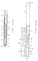
- a coaxial connector 31 also is generally similar to the known coaxial connector in that it comprises a central contact 32, an insulator holder 35, a ferrule 37 and an outer conductor sleeve 39.
- the central contact 32, insulator holder 35 and the ferrule 37 have different structures from known ones as described below.
- the contact plate section 57′ has a tapered end and the other contact plate portions 58′ extends longer than the contact plate portion 57′.
- a lateral plate section 59′ laterally extends from an extending section of the contact plate portion 58′ and has a projection plate portion 60′ projecting therefrom to the tapered end of the contact plate portion 57′.
- a gap is left between the tapered end of the contact plate portion 57′ and the projection plate portion 60′.
- connection plate portion 52′ and the contact plate part 50 as shown in Figs. 6 and 7 to form the central contact 32 comprising a connecting portion 52 and a contact portion 54 connected to each other by the coupling section 55. That is, the connecting portion 52 is formed in a U-shape, and the contact portion 54 is formed cylindrical.
- the coupling section 55 is also formed to have an offset portion 55a.
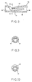
- the contact portion 54 comprises a cylindrical supporting portion 56 formed by bending the supporting plate portion 56′ in a cylindrical form, a spring contact portion 57 formed from the contact plate portion 57′ and a receiving contact portion 58 formed from the contact plate portion 58′. Therefore, the receiving contact portion 58 extends longer than the spring contact portion 57.
- the receiving contact portion 58 has a ring member 59 formed by bending the lateral plate section 59′ in a ring form and an axial guide portion 60 formed by bending the projection 60. Therefore, the guide portion 60 faces the spring contact portion 57 with a gap therebetween and serves as a guide for insertion of a pin contact.
- the spring contact portion 57 is formed to approach the receiving contact portion 58 at the tapered end portion.
- the receiving contact portion 58 is deformed to have a V-shaped section 61 at a position facing the tapered end of the spring contact portion 57, as clearly shown in Fig. 10.
- the tapered end of the spring contact portion 57 and the V-shaped section 61 come in contact with a pin contact.
- the central contact 32 is electrically and mechanically connected by press-deforming the connecting portion 52 together with the central conductor 33.
- the insulator holder 35 is a discrete sleeve body made of insulator material such as a plastic resin.
- the holder 35 is provided with first and second thick inner projections 62 and 63 at axially different positions.
- One of the first inner projections 62 engages with the offset portion 55a of the coupling section 55 to prevent axial movement of the central contact 32.
- the second inner projections 63 are in close contact with the inner sheath layer 36 to thereby be prevented from axial movement relative to the coaxial cable 34.
- the insulator holder 35 is formed in a discrete sleeve body having first and second outer projections 64 and 65 on its outer surface.
- the first and the second inner projections 62 and 63 are caused by the first and second outer rims 64 and 65, respectively, by fitting the outer conductor sleeve 39 as will later be described.
- the holder 35 is further provided with a cut-away portion 66 in an axial end.
- the ferrule 37 has an axial protrusion 67 which is fitted into the cut-away portion 66.
- the fitting of the cut-away portion 66 and the protrusion 67 serve to prevent relative rotation of the holder 35 and the ferrule 37.
- the outer conductor sleeve 39 is also fitted onto the insulator holder 35 and the ferrule 37 with clamping the folded shield 42 between the ferrule 37 and the outer conductor sleeve 39.
- the outer conductor sleeve 39 is deformed at a portion lying the shield 42 and is mechanically and electrically connected to the shield 42 and the ferrule 37.
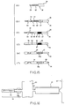
- one end of the coaxial cable 34 is worked to expose the central conductor 33 and the shield 42 as shown in Fig. 15(a). Then, the central contact 32 is connected by inserting the central conductor 33 into the U-shape connecting portion 52 and press-deforming the connecting portion 52 to form mechanical and electrical connection between the central conductor 33 and the connecting portion 52. While, the ferrule 37 is attached onto the outer jacket 38 of the coaxial cable 34 as shown in Fig. 15(b).
- the central contact 32 is formed independently from the ferrule 37 as shown in Fig. 5, but can be made together with the ferrule 37 from a metal sheet, as shown in Fig. 16.
- the central contact 32 and the carrier 51 are similar those in Figs. 6 and 7.
- the ferrule 37 and its carrier 51′ are also formed together with the central contact 32 and the carrier 51.
- the central contact 32 and the ferrule 37 are attached to the coaxial cable at the same attaching step. After attaching the central contact 32 and the ferrule 37 to the coaxial cable 34, the carriers 51 and 51′ are removed by cutting.
- the cylindrical holder 35 is fitted onto the central contact 32 and the inner sheath layer 36 as shown in Fig. 15(d) under a condition where the protrusion 67 is fitted into the cut-away portion 66 of the holder 35 as shown in Fig. 4.
- the connection of the central conductor 33 and the central contact 32 is not broken by application of an external force caused on fitting of the holder 35, because the connection is made by the press-deformation of the connecting portion 32a.
- the cylindrical outer conductor sleeve 39 is closely fitted onto the holder 35 and the folded shield 42, as shown in Fig. 15(e).
- the outer conductor sleeve 39 When the outer conductor sleeve 39 is fitted onto the holder 35, its inner surface presses the first and second outer projections 64 and 65 inwardly.
- the first outer projection 64 forms the first inner projection 62 which projects inwardly and engages the offset portion 55a, as clearly shown in Fig. 4.
- the first inner projection 62 stops axial and radial movement of the central contact 32 to prevent its movement upon insertion of the pin contact 46 into the contact portion 54.
- the second outer projections 65 form the second inner projections 63 which are in close contact with the inner sheath layer 36 so that the holder 35 is tightly clamped by the outer surface of the inner sheath layer 36 and the inner surface of the outer conductor sleeve 39 to thereby prevent relative movement of the inner sheath layer 36 and the outer conductor sleeve 39, as shown in Fig. 4.
- press deformation is outwardly carried out onto the outer conductor sleeve 39 so that the outer conductor 39 has, for example, a hexagonal section 39a at a portion which is in contact with the shield 42.
- the shield 42 is tightly clamped between the ferrule 37 and the outer conductor sleeve 39.
- the holder 35 can be made as a discrete sleeve without considering occurrence of breakage of the connection upon fitting the holder 35 of a discrete sleeve onto the central contact 32 and the inner sheath layer 36. Therefore, it is possible to reduce the occurrence rate of inferior deformation of the holder 35 and it is easy to attach the holder 35 onto the central contact 32 and the inner sheath layer 37. Further, the first and the second inner projections 62 and 63 of the holder 35 serve to prevent relative movement of the coaxial cable 34, the central contact 32, the holder 35, and the outer conductor sleeve 39.
- a coaxial multicore receptacle according to the present invention is described below which is provided with a plurality of ground pins, a plurality of power source pins, and a plurality of signal pins each of which mates with the coaxial connector described in connection with Figs. 4 to 16.
- a plurality of signals pins 71 are set upright at the centres of square areas of a matrix pattern on a main surface of an insulator substrate 72, respectively.
- a plurality of ground pins 73 and power source pins 74 are also set upright at cross points of the matrix pattern, respectively.
- the substrate 72 is usually provided with a signal processing circuit (not shown) having signal input and output lines, ground lines, and power source lines which are connected to the signal pins 71, ground pins 73, and the power source pins 74, respectively.
- the substrate 72 is also provided with pins and/or sockets on the opposite surface which are connected to the signal pins 71 and also connected to a large scale integrated circuit elements (LSIs).
- LSIs large scale integrated circuit elements
- a guide plate 75 of an insulator is laid onto the substrate 72.
- the guide plate 75 is formed with signal pin guiding holes 76, ground pin guiding holes 77, and power source pin guiding holes 78.
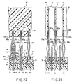
- the signal pins 71, the ground pins 73 and the power source pins 74 are inserted through the signal pin guiding holes 76, the ground pin guiding holes 77 and the power source pin guiding holes 78, respectively, as shown in Figs. 22 and 23.
- An insulator cap 79 is formed integral with an opening edge of each power source pin guiding holes 78 and is set upright on the guide plate 72, as shown in Figs. 19 and 22.
- the insulator cap 79 is formed with a tapered top end.
- Each power source pin 74 is inserted into and covered with the insulator cap 79. Therefore, the ground pin guiding holes 77 and the power source pin guiding holes 78 are arranged in rows and columns of a matrix pattern which is similar to the matrix pattern of the ground pins 73 and the power source pins 74.
- the signal pin guiding holes 76 are also disposed at the centers of square areas of the matrix pattern, respectively.
- the base plate 81 is provided with a plurality of pairs of metal strips 83a and 83b at a main surface 81a facing the guide plate 75. That is, the base plate 81 is formed with grooves 84 in the main surface 81a in registry with rows of the ground pin guiding holes 77 and the power source pin guiding holes 78 arranged in the matrix pattern.
- the paired metal strips 83a and 83b are superposed and are fitted together into each of the grooves 84. Therefore, the paired metal plates 83a and 83b extend over and along each row of the ground pin guiding holes 77 and the power source pin guiding holes 78.
- Each of the metal strips 83a and 83b is provided with a plurality of ground elements 85a and 85b which extend from different positions of each metal strip of 83a and 83b toward each opposite row of the ground pin guiding holes 77 and the power source pin guiding holes 78 in the guide plate 75.
- Each one of the ground elements 85a of one metal strip 83a is paired with adjacent one of the ground elements 85b of the other metal plate 83b paired with the one metal strip 83a.
- a pair of metal strips 83a and 83b has a plurality of pairs of ground elements 85a and 85b.
- the paired ground elements 85a and 85b elastically clamp each of the ground pins 73 and the insulator caps 79, as shown in Figs. 19, 22, and 25.
- the paired ground elements 85a and 85b have introducing portions 86a and 86b at their extending end portions.
- the introducing portions 86a and 86b are apart from each other adjacent the guide plate 75 so as to enable each of the ground pins 73 and the insulator caps 79 to be readily introduced between the paired ground elements 85a and 85b when the base plate 81 is assembled to the substrate 72 and the guide plate 75.
- some of pairs of ground elements 85a and 85b clamp ground pins 73 therebetween, respectively, as shown in Figs. 19,22, and 25 and the extending ends thereof are (that is the introducing ends 86a and 86b) are inserted into rectangular holes 87 formed in the guide plate 75.
- Each of the rectangular holes 87 is connected to each of the ground pin guiding holes 77 and is formed as an enlarged opening portion of the corresponding ground pin guiding hole 77.
- ground elements 85a and 85b clamp insulator caps 79 as shown in Figs. 19, 22, 24, and 26 and their extending ends are received in grooves 88 formed in the guide plate 75 at both sides of each insulator cap 79.
- the guide plate 75 is formed with projecting portions 89 having slant side surfaces 90 between adjacent rectangular holes 87 and between each groove 88 and one rectangular hole 87 adjacent the groove 88, so that the extending ends of the ground elements 85a and 85b can readily be inserted into the rectangular holes 87 and the grooves 88 when the base plate 81 is assembled with the guide plate 75.
- ground elements 85a, the ground plates 91a and the metal strip 83a are formed as a integral body by punching a sheet of metal plate.
- the ground elements 85b, the ground plates 91b and the metal strip 83b are also formed as an integral body.
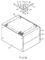
- first two side frames 93 and second two side frames 94 are attached to first opposite sides and second opposite sides of the base plate 81, respectively, to form a space on the main surface 81a of the base plate 81 in which the ground elements 85a and 85b and ground plates 91a and 91b are disposed.
- the guide plate 75 is attached onto the first and second side frames 93 and 94 to close the space as shown in Fig. 29.
- the insulator cap 79 is reliably inserted between the ground elements 85a and 85b because the insulator cap 79 has the tapered end as shown in Fig. 26 and because the ground elements 85a and 85b have the introducing portions 86a and 86b.
- an assembly is obtained which comprises the base plate 81, first and second side frames 92 and 93, and guide plate 75 as shown in Fig. 29.
- the substrate 72 is mounted on the guide plate 75 with signal pins 71, ground pins 73, and power source pins 74 being inserted into the signal pin guiding holes 76, ground pins guiding holes 77, and power source pin guiding holes 78, respectively, as shown in Figs. 22 and 23.
- the insulator caps 79 are formed integral with the guide plate 75, normal receptacles can be assembled without fault under a correct design even if positional relationship is complex between the ground pins 73 and the power source pins 74.
Landscapes
- Coupling Device And Connection With Printed Circuit (AREA)
- Multi-Conductor Connections (AREA)
Claims (7)
- Connecteur coaxial de type mince (31) destiné à être utilisé pour brancher électriquement et mécaniquement une extrémité d'un câble coaxial (34) comprenant un conducteur central (33) isolé d'un conducteur extérieur (42) par un isolateur intérieur (36), et une gaine d'isolation extérieure (38), cette gaine d'isolation extérieure (38) et l'isolateur intérieur (36) étant découpés à l'extrémité du câble pour dénuder le conducteur central (33), l'isolateur intérieur (36) et le conducteur extérieur (42) constituant ainsi respectivement un conducteur central dénudé (33), un isolateur intérieur dénudé (36) et un conducteur extérieur dénudé (42), le connecteur coaxial (31) comprenant un contact central (32) devant être branché électriquement et mécaniquement au conducteur central dénudé (33), un porte-isolateur (35) destiné à maintenir le contact central (32) solidaire de l'isolateur intérieur dénudé (36), une virole (37) devant être montée sur la gaine extérieure (38), et un manchon conducteur extérieur (39) s'adaptant sur le porte-isolateur (35) et sur la virole (37), ce manchon conducteur extérieur (39) comportant une partie de déformation (39a) destinée à bloquer étroitement le conducteur extérieur dénudé (42) et la virole (37), après déformation par pression, connecteur caractérisé en ce que le contact central (32) est muni d'une partie de branchement devant être déformée par pression pour se coupler ainsi mécaniquement et électriquement au conducteur central dénudé (33), le porte-isolateur (35) consistant en un corps de manchon réalisé dans un matériau d'isolateur et comportant des saillies intérieures (62, 63) faisant saillie radialement vers l'intérieur et venant respectivement en contact de pression avec le contact central (32) et avec l'isolateur intérieur dénudé (42), ce porte-isolateur (35) et la virole (37) étant disposés l'un contre l'autre dans la direction axiale de façon que leurs extrémités axiales viennent en face l'une de l'autre et s'engagent l'une dans l'autre pour empêcher toute rotation relative de celles-ci.
- Connecteur coaxial de type mince selon la revendication 1, caractérisé en ce que le contact central (32) est un contact femelle destiné à s'accoupler à une broche de contact (46).
- Connecteur coaxial de type mince selon la revendication 2, caractérisé en ce que le contact femelle comprend la partie de branchement (52), une première partie de contact (57) s'étendant axialement de la partie de branchement (52) à une première extrémité en saillie et comportant une première surface de contact intérieure, une seconde partie de contact (58) disposée le long de la première partie de contact (54) en partant de la partie de branchement (52), avec un intervalle progressivement réduit entre les deux, et comportant une extrémité en saillie arrivant plus court que la première extrémité en saillie, un élément de forme annulaire (59) monté sur la première extrémité en saillie et définissant une ouverture de réception de la broche de contact (46) et une partie de guidage axial (60) partant axialement de l'élément en forme d'anneau (59) le long de la première partie de contact (57) en direction de la seconde extrémité de contact mais plus court que celle-ci, de manière à guider la broche de contact (46) introduite par cette ouverture dans l'intervalle compris entre la première partie de contact et la seconde partie de contact (57, 58).
- Prise femelle coaxiale à noyaux multiples destinée à s'accoupler à un certain nombre de connecteurs coaxiaux de type mince (31) correspondant chacun à la revendication 2, comprenant un substrat (72) réalisé dans un matériau isolant et comportant une surface principale ;- un certain nombre de broches de masse (73) et de broches d'alimentation de puissance montées (74) perpendiculairement sur la surface principale et disposées dans une configuration de matrice de rangées et de colonnes dans le substrat (72), cette configuration de matrice comportant un certain nombre de zones carrées élémentaires définies chacune par deux rangées adjacentes de ces rangées et deux colonnes adjacentes de ces colonnes ;- un certain nombre de broches de signaux (71) montées perpendiculairement sur la surface principale du substrat (72), chaque broche de signal (71) étant placée à peu près au centre de la zone carrée élémentaire, et chaque broche de signal (71) étant destinée à constituer la broche de contact (46) devant être accouplée au contact femelle du connecteur coaxial ;- une plaque de guidage (75) formant un isolateur étalé sur la surface principale du substrat (72) et comportant un certain nombre de trous (77) de guidage de broches de masse ; un certain nombre de trous (78) de guidage de broches d'alimentation et un certain nombre de trous (76) de guidage de broches de signaux, dans lesquels on introduit respectivement les broches de masse (73), les broches d'alimentation (74) et les broches de signaux (71) ;- des capuchons d'isolateurs (79) formés d'une seule pièce avec les bords d'ouverture des trous (77) de guidage de broches d'alimentation et montés perpendiculairement sur la plaque de guidage (75), les broches d'alimentation (74) étant introduites respectivement dans ces capuchons d'isolateurs (79) et recouvertes par ceux-ci ;- une plaque de base (81) d'un matériau d'isolateur montée de façon fixe sur la plaque de guidage (75) avec un intervalle d'espacement entre les deux et comportant des trous (82) de réception de connecteurs coaxiaux coïncidant respectivement avec les trous (76) de guidage de broches de signaux, de manière à recevoir ces connecteurs coaxiaux (31) pour qu'on puisse accoupler respectivement ces connecteurs coaxiaux (31) avec les broches de signaux (71) ;- un certain nombre de paires de premiers éléments de masse et de seconds éléments de masse métalliques (85a, 85b) montées respectivement sur la plaque de base (81) et faisant saillie sur celle-ci respectivement en direction des trous (77) de guidage de broches de masse et des trous (78) de guidage de broches d'alimentation, de manière à venir en contact avec les broches de masse (73) et à bloquer respectivement les capuchons d'isolateurs (79) ; et- un certain nombre de paires de premières plaques de masse et de secondes plaques de masse métalliques (91a, 91b) montées sur la plaque de base (81) et faisant saillie sur celle-ci entre des paires adjacentes des premiers éléments de masse et des seconds éléments de masse (85a, 85b) en direction de la plaque de guidage (75) pour pouvoir venir en contact avec les connecteurs coaxiaux adjacents (31) introduits dans les trous (82) de réception de connecteurs coaxiaux.
- Prise femelle coaxiale à noyaux multiples selon la revendication 4, caractérisée en ce que les premiers éléments de masse et les seconds éléments de masse (85a, 85b) comportent respectivement des extrémités en saillie (86a, 86b) adjacentes à la plaque de guidage (75), la plaque de guidage (75) étant en outre munie d'une paire de rainures (88) formées dans sa surface des deux côtés de chacun des capuchons d'isolateurs (79) pour recevoir respectivement les extrémités en saillie (86a, 86b) de chaque paire de premiers éléments de masse et de seconds éléments de masse (85a, 85b) correspondant à chaque capuchon d'isolateur (79).
- Prise femelle coaxiale à noyaux multiples selon l'une quelconque des revendications 4 et 5, caractérisée en ce que les premiers éléments de masse et les seconds éléments de masse (85a, 85b) comportent respectivement des extrémités en saillie (86a, 86b) au voisinage de la plaque de guidage (75), cette plaque de guidage (75) étant munie d'un trou agrandi (87) percé dans sa surface à l'endroit d'un bord d'ouverture de chacun des trous (77) de guidage de broches de masse, de manière à recevoir en commun les extrémités en saillie (86a, 86b) de chacune des première paires et des secondes paires d'éléments de masse (85a, 85b) correspondant à chaque broche de masse (73).
- Prise femelle coaxiale à noyaux multiples selon l'une quelconque des revendications 4 à 6, caractérisée en ce que les premières plaques de masse et les secondes plaques de masse (91a, 91b) comportent respectivement des extrémités en saillie au voisinage de la plaque de guidage (75), cette plaque de guidage (75) étant munie d'un trou d'engagement (92) dans la surface de celle-ci au voisinage du trou (76) de guidage de broches de signaux, de manière à recevoir en commun les extrémités en saillie de chaque paire de premières plaques de masse et de secondes plaques de masse (91a, 91b) correspondant à chaque broche de signal (71).
Applications Claiming Priority (6)
| Application Number | Priority Date | Filing Date | Title |
|---|---|---|---|
| JP138727/87 | 1987-06-02 | ||
| JP1987138727U JPH0414867Y2 (fr) | 1987-09-09 | 1987-09-09 | |
| JP154828/87 | 1987-10-09 | ||
| JP1987154828U JPH026628Y2 (fr) | 1987-10-09 | 1987-10-09 | |
| JP6589588U JPH01168968U (fr) | 1988-05-20 | 1988-05-20 | |
| JP65895/88 | 1988-05-20 |
Publications (3)
| Publication Number | Publication Date |
|---|---|
| EP0306975A2 EP0306975A2 (fr) | 1989-03-15 |
| EP0306975A3 EP0306975A3 (en) | 1990-09-05 |
| EP0306975B1 true EP0306975B1 (fr) | 1993-04-07 |
Family
ID=27298966
Family Applications (1)
| Application Number | Title | Priority Date | Filing Date |
|---|---|---|---|
| EP88114785A Expired - Lifetime EP0306975B1 (fr) | 1987-09-09 | 1988-09-09 | Connecteur coaxial de type mince et prise femelle accouplable aux connecteurs coaxiaux |
Country Status (4)
| Country | Link |
|---|---|
| US (1) | US4898545A (fr) |
| EP (1) | EP0306975B1 (fr) |
| CA (1) | CA1286742C (fr) |
| DE (1) | DE3880057T2 (fr) |
Families Citing this family (8)
| Publication number | Priority date | Publication date | Assignee | Title |
|---|---|---|---|---|
| DE9215782U1 (de) * | 1992-11-20 | 1993-01-07 | kabelmetal electro GmbH, 3000 Hannover | Vorrichtung zur Kontaktierung des Innenleiters eines koaxialen Hochfrequenz-Kabels |
| US5474470A (en) * | 1994-03-30 | 1995-12-12 | Itt Corporation | Compensated interface coaxial connector apparatus |
| US6068630A (en) * | 1997-01-02 | 2000-05-30 | St. Francis Medical Technologies, Inc. | Spine distraction implant |
| US7544070B2 (en) * | 2004-07-02 | 2009-06-09 | Seagate Technology Llc | Electrical connector defining a power plane |
| CN101960676A (zh) * | 2007-12-28 | 2011-01-26 | 欧多诗贝有限公司 | 在高速数据应用中使用的低成本连接器装置和方法 |
| JP5868140B2 (ja) | 2011-11-21 | 2016-02-24 | 富士通コンポーネント株式会社 | 同軸ケーブル接続モジュール、同軸ケーブル用多極コネクタ及び多極複合コネクタ |
| HUE045125T2 (hu) * | 2016-05-04 | 2019-12-30 | Md Elektronik Gmbh | Kábel |
| JP6734767B2 (ja) * | 2016-11-30 | 2020-08-05 | 日本航空電子工業株式会社 | コネクタ |
Family Cites Families (9)
| Publication number | Priority date | Publication date | Assignee | Title |
|---|---|---|---|---|
| US3539976A (en) * | 1968-01-04 | 1970-11-10 | Amp Inc | Coaxial connector with controlled characteristic impedance |
| US3923367A (en) * | 1974-05-08 | 1975-12-02 | Hughes Aircraft Co | Simultaneous double crimp coaxial cable contact assembly |
| US4076369A (en) * | 1976-07-26 | 1978-02-28 | Northern Telecom Limited | Box terminal for card edge receptacles in telecommunications systems and the like |
| FR2497006A1 (fr) * | 1980-12-24 | 1982-06-25 | Ind Electro Ste Gle | Contacts electriques pour cables coaxiaux et cables bifilaires |
| CA1209661A (fr) * | 1983-08-05 | 1986-08-12 | Thomas M. Cairns | Connecteur electrique miniature pour circuits electriques de faible puissance |
| US4509816A (en) * | 1983-08-31 | 1985-04-09 | Wolfgang Freitag | Plug connector for co-axial electrical cables |
| JPS618981U (ja) * | 1984-06-22 | 1986-01-20 | 日本航空電子工業株式会社 | 同軸ケ−ブル用コネクタ |
| US4611867A (en) * | 1985-07-08 | 1986-09-16 | Japan Aviation Electronics Industry Limited | Coaxial multicore receptacle |
| JPH06266187A (ja) * | 1993-03-11 | 1994-09-22 | Ricoh Co Ltd | 画像形成装置および画像形成方法 |
-
1988
- 1988-09-06 US US07/240,943 patent/US4898545A/en not_active Expired - Lifetime
- 1988-09-09 CA CA000576879A patent/CA1286742C/fr not_active Expired
- 1988-09-09 EP EP88114785A patent/EP0306975B1/fr not_active Expired - Lifetime
- 1988-09-09 DE DE8888114785T patent/DE3880057T2/de not_active Expired - Fee Related
Also Published As
| Publication number | Publication date |
|---|---|
| DE3880057D1 (de) | 1993-05-13 |
| EP0306975A3 (en) | 1990-09-05 |
| EP0306975A2 (fr) | 1989-03-15 |
| CA1286742C (fr) | 1991-07-23 |
| US4898545A (en) | 1990-02-06 |
| DE3880057T2 (de) | 1993-08-12 |
Similar Documents
| Publication | Publication Date | Title |
|---|---|---|
| KR100256927B1 (ko) | 고속 케이블의 차폐부 접속 시스템 | |
| EP0327308B1 (fr) | Famille de connecteurs microcoaxiaux | |
| US4310208A (en) | Molded electrical connector | |
| US6482045B2 (en) | Connector socket, connector plug and connector assembly | |
| EP0297699B1 (fr) | Connecteurs pour câble plat | |
| JP3415889B2 (ja) | シールドコネクタ | |
| EP0118168B2 (fr) | Connecteur électrique enfichable et prise assortie | |
| KR960002138B1 (ko) | 모듈형 전기 커넥터 | |
| EP0094173B1 (fr) | Connecteur électrique à élément commun de connexion | |
| US6814624B2 (en) | Telecommunications jack assembly | |
| US4725249A (en) | Connector assembly | |
| US4697862A (en) | Insulation displacement coaxial cable termination and method | |
| US5618202A (en) | Connector having strip line structure | |
| US4713023A (en) | Electrical connector and method of assembly | |
| US4379361A (en) | Method for making molded electrical connector | |
| US5478252A (en) | Disconnectable male connector for communications networks | |
| EP0203793A2 (fr) | Terminaison d'un câble coaxial par déplacement d'isolation et méthode | |
| US5775924A (en) | Modular terminating connector with frame ground | |
| EP0211949B1 (fr) | Adaptateur pour cable coaxial | |
| EP0620614A1 (fr) | Assemblage de connecteur électrique | |
| KR20060065615A (ko) | 전기 커넥터 시스템 | |
| EP0265179A2 (fr) | Prise à fiches et connecteur à douilles avec contacts à déplacement d'isolant | |
| JP3262198B2 (ja) | コネクタ | |
| US4898545A (en) | Thin-type coaxial connector and receptacle for mating with the coaxial connectors | |
| US5997348A (en) | Electrical assembly with grounding strip connecting cable screens |
Legal Events
| Date | Code | Title | Description |
|---|---|---|---|
| PUAI | Public reference made under article 153(3) epc to a published international application that has entered the european phase |
Free format text: ORIGINAL CODE: 0009012 |
|
| 17P | Request for examination filed |
Effective date: 19880909 |
|
| AK | Designated contracting states |
Kind code of ref document: A2 Designated state(s): BE DE FR GB IT NL |
|
| PUAL | Search report despatched |
Free format text: ORIGINAL CODE: 0009013 |
|
| AK | Designated contracting states |
Kind code of ref document: A3 Designated state(s): BE DE FR GB IT NL |
|
| 17Q | First examination report despatched |
Effective date: 19920806 |
|
| GRAA | (expected) grant |
Free format text: ORIGINAL CODE: 0009210 |
|
| ITF | It: translation for a ep patent filed | ||
| AK | Designated contracting states |
Kind code of ref document: B1 Designated state(s): BE DE FR GB IT NL |
|
| RIN1 | Information on inventor provided before grant (corrected) |
Inventor name: TOKAICHI, TETSURO Inventor name: UEKIDO, KOUZOU Inventor name: KOMOTO, MITSUO Inventor name: SUZUKI, TAKAO C/O JAPAN AVIATION ELECTRONICS Inventor name: ENDO, HIROSHI C/O JAPAN AVIATION ELECTRONICS |
|
| ET | Fr: translation filed | ||
| REF | Corresponds to: |
Ref document number: 3880057 Country of ref document: DE Date of ref document: 19930513 |
|
| PLBE | No opposition filed within time limit |
Free format text: ORIGINAL CODE: 0009261 |
|
| STAA | Information on the status of an ep patent application or granted ep patent |
Free format text: STATUS: NO OPPOSITION FILED WITHIN TIME LIMIT |
|
| 26N | No opposition filed | ||
| PGFP | Annual fee paid to national office [announced via postgrant information from national office to epo] |
Ref country code: BE Payment date: 19990823 Year of fee payment: 12 |
|
| PGFP | Annual fee paid to national office [announced via postgrant information from national office to epo] |
Ref country code: GB Payment date: 19990908 Year of fee payment: 12 |
|
| PGFP | Annual fee paid to national office [announced via postgrant information from national office to epo] |
Ref country code: FR Payment date: 19990929 Year of fee payment: 12 |
|
| PGFP | Annual fee paid to national office [announced via postgrant information from national office to epo] |
Ref country code: NL Payment date: 19990930 Year of fee payment: 12 Ref country code: DE Payment date: 19990930 Year of fee payment: 12 |
|
| PG25 | Lapsed in a contracting state [announced via postgrant information from national office to epo] |
Ref country code: GB Free format text: LAPSE BECAUSE OF NON-PAYMENT OF DUE FEES Effective date: 20000909 |
|
| PG25 | Lapsed in a contracting state [announced via postgrant information from national office to epo] |
Ref country code: BE Free format text: LAPSE BECAUSE OF NON-PAYMENT OF DUE FEES Effective date: 20000930 |
|
| BERE | Be: lapsed |
Owner name: NEC CORP. Effective date: 20000930 Owner name: JAPAN AVIATION ELECTRONICS INDUSTRY LTD Effective date: 20000930 |
|
| PG25 | Lapsed in a contracting state [announced via postgrant information from national office to epo] |
Ref country code: NL Free format text: LAPSE BECAUSE OF NON-PAYMENT OF DUE FEES Effective date: 20010401 |
|
| GBPC | Gb: european patent ceased through non-payment of renewal fee |
Effective date: 20000909 |
|
| PG25 | Lapsed in a contracting state [announced via postgrant information from national office to epo] |
Ref country code: FR Free format text: LAPSE BECAUSE OF NON-PAYMENT OF DUE FEES Effective date: 20010531 |
|
| NLV4 | Nl: lapsed or anulled due to non-payment of the annual fee |
Effective date: 20010401 |
|
| PG25 | Lapsed in a contracting state [announced via postgrant information from national office to epo] |
Ref country code: DE Free format text: LAPSE BECAUSE OF NON-PAYMENT OF DUE FEES Effective date: 20010601 |
|
| REG | Reference to a national code |
Ref country code: FR Ref legal event code: ST |
|
| PG25 | Lapsed in a contracting state [announced via postgrant information from national office to epo] |
Ref country code: IT Free format text: LAPSE BECAUSE OF NON-PAYMENT OF DUE FEES;WARNING: LAPSES OF ITALIAN PATENTS WITH EFFECTIVE DATE BEFORE 2007 MAY HAVE OCCURRED AT ANY TIME BEFORE 2007. THE CORRECT EFFECTIVE DATE MAY BE DIFFERENT FROM THE ONE RECORDED. Effective date: 20050909 |