EP0307048A2 - Zellkulturkolben mit einer Membranbarriere - Google Patents
Zellkulturkolben mit einer Membranbarriere Download PDFInfo
- Publication number
- EP0307048A2 EP0307048A2 EP88201922A EP88201922A EP0307048A2 EP 0307048 A2 EP0307048 A2 EP 0307048A2 EP 88201922 A EP88201922 A EP 88201922A EP 88201922 A EP88201922 A EP 88201922A EP 0307048 A2 EP0307048 A2 EP 0307048A2
- Authority
- EP
- European Patent Office
- Prior art keywords
- chamber
- housing
- gas
- media
- cell culture
- Prior art date
- Legal status (The legal status is an assumption and is not a legal conclusion. Google has not performed a legal analysis and makes no representation as to the accuracy of the status listed.)
- Granted
Links
Images



Classifications
-
- C—CHEMISTRY; METALLURGY
- C12—BIOCHEMISTRY; BEER; SPIRITS; WINE; VINEGAR; MICROBIOLOGY; ENZYMOLOGY; MUTATION OR GENETIC ENGINEERING
- C12M—APPARATUS FOR ENZYMOLOGY OR MICROBIOLOGY; APPARATUS FOR CULTURING MICROORGANISMS FOR PRODUCING BIOMASS, FOR GROWING CELLS OR FOR OBTAINING FERMENTATION OR METABOLIC PRODUCTS, i.e. BIOREACTORS OR FERMENTERS
- C12M23/00—Constructional details, e.g. recesses, hinges
- C12M23/02—Form or structure of the vessel
- C12M23/08—Flask, bottle or test tube
-
- C—CHEMISTRY; METALLURGY
- C12—BIOCHEMISTRY; BEER; SPIRITS; WINE; VINEGAR; MICROBIOLOGY; ENZYMOLOGY; MUTATION OR GENETIC ENGINEERING
- C12M—APPARATUS FOR ENZYMOLOGY OR MICROBIOLOGY; APPARATUS FOR CULTURING MICROORGANISMS FOR PRODUCING BIOMASS, FOR GROWING CELLS OR FOR OBTAINING FERMENTATION OR METABOLIC PRODUCTS, i.e. BIOREACTORS OR FERMENTERS
- C12M23/00—Constructional details, e.g. recesses, hinges
- C12M23/24—Gas permeable parts
-
- C—CHEMISTRY; METALLURGY
- C12—BIOCHEMISTRY; BEER; SPIRITS; WINE; VINEGAR; MICROBIOLOGY; ENZYMOLOGY; MUTATION OR GENETIC ENGINEERING
- C12M—APPARATUS FOR ENZYMOLOGY OR MICROBIOLOGY; APPARATUS FOR CULTURING MICROORGANISMS FOR PRODUCING BIOMASS, FOR GROWING CELLS OR FOR OBTAINING FERMENTATION OR METABOLIC PRODUCTS, i.e. BIOREACTORS OR FERMENTERS
- C12M23/00—Constructional details, e.g. recesses, hinges
- C12M23/34—Internal compartments or partitions
-
- C—CHEMISTRY; METALLURGY
- C12—BIOCHEMISTRY; BEER; SPIRITS; WINE; VINEGAR; MICROBIOLOGY; ENZYMOLOGY; MUTATION OR GENETIC ENGINEERING
- C12M—APPARATUS FOR ENZYMOLOGY OR MICROBIOLOGY; APPARATUS FOR CULTURING MICROORGANISMS FOR PRODUCING BIOMASS, FOR GROWING CELLS OR FOR OBTAINING FERMENTATION OR METABOLIC PRODUCTS, i.e. BIOREACTORS OR FERMENTERS
- C12M23/00—Constructional details, e.g. recesses, hinges
- C12M23/38—Caps; Covers; Plugs; Pouring means
-
- C—CHEMISTRY; METALLURGY
- C12—BIOCHEMISTRY; BEER; SPIRITS; WINE; VINEGAR; MICROBIOLOGY; ENZYMOLOGY; MUTATION OR GENETIC ENGINEERING
- C12M—APPARATUS FOR ENZYMOLOGY OR MICROBIOLOGY; APPARATUS FOR CULTURING MICROORGANISMS FOR PRODUCING BIOMASS, FOR GROWING CELLS OR FOR OBTAINING FERMENTATION OR METABOLIC PRODUCTS, i.e. BIOREACTORS OR FERMENTERS
- C12M29/00—Means for introduction, extraction or recirculation of materials, e.g. pumps
- C12M29/04—Filters; Permeable or porous membranes or plates, e.g. dialysis
Definitions
- This invention relates to a culture flask for the culturing of cells and, more particularly, to a two chamber flask with a gas permeable membrane separating the two chambers.
- the culturing of living cells in vitro is commonly carried out for a variety of purposes, such as medical, biological or genetic research.
- the cells are grown in media which contains nutrients and other constituents required for cell metabolism, growth and proliferation. Subsequently the cells and/or their by-products may be removed from the media and utilized or analyzed.
- U.S. Patent Nos. 4,225,671 and 3,941,662 disclose devices in which a gas permeable membrane forms one complete surface of a culture container.
- the membrane vessel structures are complex to assemble and costly to manufacture.
- U.S. Patent No. 4,201,845 discloses a cell culture reactor which is formed of an open-topped housing having media inlet ports, a gas inlet port and a gas outlet port.
- a lid has a media outlet port and an access port for sampling or inoculation.
- a layer of gas permeable hollow fibers is positioned in the lower housing and is supported on a plate having a plurality of holes.
- the gas inlet port and gas outlet port each communicate directly with the hollow fibers for aeration of the inside of the fibers and the media flows around the hollow fibers.
- hollow fibers in laboratory scale culturing are rather cumbersome to use and the device of such is expensive to manufacture.
- grown cells are difficult to remove intact from a layer of hollow fibers which are characteristically somewhat fragile.
- a biologist or medical researcher will stain the cells for study under a microscope. This involves a tedious process of transferring the cells to a microscope slide and then fixing and staining the cells. Cells may become distorted, damaged or ajuxtaposed in transferring them from a flask or other standard vessel to a microscope slide, thus making cell study and/or observation inconvenient and possibly incomplete.
- a cell culture flask which includes a hollow housing and a gas permeable membrane disposed within the housing and dividing the housing into a first chamber and a second chamber.
- a retaining means for removably securing the gas permeable membrane within the housing is provided and forms a liquid-tight seal between the first chamber and the second chamber.
- a gas inlet is provided into the housing and communicates with the first chamber for supplying gas thereto.
- a media inlet is provided into the housing and communicates with the second chamber for providing cell growth media thereto.
- the cell culture flask can include a media outlet from the housing that communicates with the second housing for discharging cell growth media therefrom.
- the cell culture flask has a housing which is an open-topped structure having a base and a peripheral wall.
- the retaining means is a retaining ring conforming to an inner geometric diameter of the peripheral wall.
- the membrane is frictionally held in place by compressing an outer perimeter of the membrane between an outer surface of the retaining ring and an inner surface of the housing.
- a gas outlet from the housing that communicates with the first chamber can also be included.
- the housing is an open-topped structure having a base, a peripheral outer wall and a peripheral inner wall.
- the retaining means is a retaining ring conforming to a perimeter of the peripheral inner wall.
- the membrane is frictionally held in place by compressing an outer perimeter of the membrane between a surface of the retaining ring and a surface of the peripheral inner wall.
- the first chamber is below the membrane and within the peripheral inner wall.
- a portion of the retaining ring rests against a portion of the peripheral outer wall and forms an intermediate chamber.
- the retaining ring forms a liquid and gas seal between the intermediate chamber and the second chamber.
- the gas inlet communicates with the intermediate chamber and the peripheral inner wall has an opening positioned below the retaining ring and in fluid communication with the intermediate chamber.
- Another embodiment is an open-bottomed structure having a top and a peripheral wall.
- the membrane is positioned over the bottom.
- the retaining means is a retaining ring conforming to the perimeter of the peripheral wall.
- the membrane is frictionally held in place by compressing an outer perimeter of the membrane between a surface of the retaining ring and a surface of the peripheral wall.
- the retaining ring can also have a bottom surface that is adapted to rest on a base unit that has means for supplying gas to the first chamber.
- Another embodiment is an open-topped hollow housing that includes a base and a peripheral wall.
- a gas permeable membrane is disposed over the open top and the peripheral wall of the housing.
- a retaining ring is provided for securing the gas permeable membrane about an outer surface of the peripheral wall.
- the retaining ring conforms to an outer geometric diameter of the peripheral wall.
- the membrane is frictionally held in place by compressing an outer perimeter of the membrane between an inner surface of the retaining ring and an outer surface of the housing.
- the retaining ring extends above the peripheral wall.
- a first chamber is formed below the membrane and a second chamber is formed above the membrane and within the inner surface of the retaining ring.
- a gas inlet is provided into the housing and communicates with the first chamber for supplying gas thereto.
- the gas permeable membrane utilized in accordance with this invention can be transparent so that cultured cells may be stained on the membrane and viewed and studied under a microscope.
- the flasks may also be transparent in order that the cells may be observed during the culturing process.
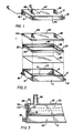
- the cell culture flask 2 includes an open-topped, hollow housing 4.
- the housing 4 is preferably rectangularly-shaped and includes a base 6 and a peripheral wall formed of opposed and parallel walls 8 and 9, and walls 10 and 11 opposed and parallel to each other. Wall 10 and wall 11 are connected between walls 8 and 9.
- the walls 8-11 all about the same height, extend upwardly from the base 6 along its outer peripheral edges and are integral therewith.
- Wall 8 includes a gas inlet 16 therethrough, preferably located near a lower corner adjacent wall 10.
- Wall 9 includes a gas outlet I8 therethrough, preferably located near a lower corner adjacent wall 11.
- the gas inlet 16 and gas outlet 18 are preferably diagonally opposed to each other in order to optimize gas flow through the cell culture flask 2.
- the gas inlet 16 and gas outlet 18 may be hollow nipples as shown in the figures, or may be any similar device for establishing fluid flow through the housing 4.
- a gas permeable membrane 20 is positioned within the housing 4.
- the gas permeable membrane 20 is rectangularly-shaped and somewhat larger than the outer dimensions of base 6.
- the gas permeable membrane 20 is made from any material which is impervious to liquids, promotes cell growth thereon and permits the flow of gas therethrough. Suitable materials include fluorinated ethylene propylene copolymers, polycarbonates, polyethylene copolymers, ethylene copolymers, polypropylene and fluroplastics.
- the membrane may be treated to promote the adherence of cells to the membrane, such as etching a surface of the membrane.
- the gas permeable membrane 20 is positioned above the base 6 of the housing 4 and also above the gas inlet 16 and the gas outlet 18 and is held in place by a retaining ring 22.
- the retaining ring 22 is rectangularly-shaped and includes opposed and parallel side walls 24 and 25 and walls 26 and 27 which are opposed and parallel to each other. Side walls 26 and 27 are positioned between and connected to side walls 24 and 25. Side walls 24 and 25 are also perpendicular to side walls 26 and 27. An inwardly oriented lower lip 32 formed at the lower edge of side walls 24-27 may be an integral portion of the retaining ring 22.
- the height of side walls 24-27 of the retaining ring 22 is less than the height of the walls 8-11 of the housing 4.
- the outer dimensions of the retaining ring 22 are slightly smaller than the inner dimensions of the housing 4 so that the retaining ring 22 may be positioned within the housing 4.
- the lower lip 32 of the retaining ring 22 is in contact with the gas permeable membrane 20 and walls 24-27 of the retaining ring 22 compress the outer perimeter of the membrane 20 against walls 8-11 of the housing 4 so that the retaining ring 22 and the membrane 20 are held in place within the housing 4 by frictional engagement.
- a top edge 34 of the housing 4 is preferably aligned with a top edge 36 of the retaining ring 22.
- a lid 42 having a rectangular shape slightly larger than the peripheral wall formed by walls 8-11 is positioned on top of the housing 4 inclusive of the retaining ring 22.
- the lid 42 has a downwardly directed lip 44 which extends around an outer perimeter of the lid 42.
- the lip 44 of the lid 42 is adjacent the outer surface of walls 8-11 and functions to align the lid 42 onto the housing 4.
- the lid 42 also includes a media inlet 46 and a media outlet 48 extending therethrough and can be molded into the lid 42.
- the media inlet 46 and media outlet 48 alternatively may extend through one of the side surfaces.
- the media inlet 46 and the media outlet 48 are spaced apart on the lid 42 so that an optimum flow of cell culture media may be supplied to an upper surface of the gas permeable membrane 20.
- the media inlet 46 and media outlet 48 may be hollow nipples as shown, although other liquid flow connectors may be used including inwardly oriented ports.
- the cell culture flask 2 is divided into two chambers, a bottom or first chamber 50 between the gas permeable membrane 20 and the base 6 of the housing 4, and a top or second chamber 52 between the gas permeable membrane 20 and the lid 42.
- a liquid-tight seal is formed between the bottom chamber 50 and the top chamber 52 by the gas permeable membrane 20 and the retaining ring 22.
- the cell culture flask 2 shown in Figs. 1-3 is used to grow cells as follows:
- the gas permeable membrane 20 is positioned within the housing 4 and is held in place by the retaining ring 22.
- a sample of cell culture is placed in the top chamber 52 onto a top surface of the gas permeable membrane 20.
- the lid 42 is then positioned on the housing 4.
- Cell culture media is supplied to the top chamber 52 through media inlet 46 and will exit through the media outlet 48.
- a supply gas line is connected to the gas inlet 16 and an exit gas line is connected to the gas outlet 18.
- the gas supplied may be any gas suitable for cell growth such as oxygen, carbon dioxide or nitrogen, or a mixture of these gases.
- the gas is supplied to the gas inlet 16 at a pressure equal to or higher than the gas exiting through the gas outlet 18.
- the exit line from the gas outlet 18 may be restricted or closed completely to allow pressurized gas to remain in the lower chamber while the flow is interrupted for predetermined intervals.
- the gas pressure in the bottom chamber 50 is also higher than the gas pressure in the top chamber 52 and enables a portion of the gas supplied to the bottom chamber 50 to permeate through the gas permeable membrane 20.
- the growing cells are directly supplied with gas. Gas also bubbles through the media, resulting in an aeration of the media in the top chamber 52.
- the gas will also exit the flask 2 through both the media outlet 48 and the interface between the lip 44 of the lid 42 and walls 8-11 of the housing 4. Gas waste products produced by the cells during growth are released from the flask 2 in a similar fashion.
- flask 2 of this embodiment discloses an aerobic cell culture arrangement
- anaerobic cell cultures can also be accommodated by eliminating the gas supply to the gas inlet 16 and sealing gas inlet 16 and gas outlet 18.
- the liquid growth media is supplied to the top chamber 52 through the media inlet 46.
- the media rests above the cells which are on the top surface of the gas permeable membrane 20.
- a constant supply of fresh media may be supplied to the flask 2 through the media inlet 46 and spent media may be removed from the flask 2 through the media outlet 48.
- the media is removed and the gas permeable membrane 20, now having a layer of cells thereon, is removed intact either by cutting the membrane 20 about its outer edges or by removing the retaining ring 22 from the housing 4 and removing the entire gas permeable membrane 20.
- the gas permeable membrane 20 is transparent so that the cells may be directly fixed, stained and viewed under a microscope.
- the transparent membrane with cells may be mounted on various sizes of glass or plastic matrices, i.e., a 75 mm. x 25 mm. microscope slide, for convenient handling or viewing. This arrangement provides a quick and efficient means for cell study since there is little risk of disrupting the cells such as is possible in conventional cell culturing where the cells are mechanically or enzymatically removed and transferred from the flask/media to microscope slides.
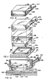
- FIG. 4-6 A second embodiment of the cell culture flask 60 in accordance with the present invention is shown in Figs. 4-6.
- This embodiment utilizes the same housing 4 and the same gas permeable membrane 20 as that of the flask 2. Accordingly, like reference numerals are used for like parts in this embodiment.
- the gas permeable membrane 20 is positioned above the base 6 of the housing 4.
- the membrane 20 is also positioned above the gas inlet 16 and the gas outlet 18 and rests on the top edge 34 of the housing 4 so that it extends over walls 8-11 of the housing 4.
- the membrane 20 is held in place by a retaining ring 62.
- the retaining ring 62 is rectangularly-shaped and includes opposed and parallel walls 64 and 65 and walls 66 and 67 which are opposed and parallel to each other.
- Walls 66 and 67 are positioned between and connected to walls 64 and 65. Walls 64 and 65 are also perpendicular to walls 66 and 67.
- the inner dimensions of the retaining ring 62 are slightly larger than the outer dimensions of the housing 4 so that the retaining ring 62 may be positioned around the outer perimeter of the housing 4 about walls 8-11.
- Walls 64-67 of the retaining ring 62 compress the outer perimeter of the membrane 20 against the outer surfaces of walls 8-11 of the housing 4 so that the retaining ring 62 and the membrane 20 are held in place.
- the top edge 34 of the housing 4 is positioned below a top edge 68 of the retaining ring 62.
- a lid 82 having a rectangular shape slightly larger than the outer geometric diameter of the retaining ring 62 formed by walls 64-67 is positioned on top edge 66 of the retaining ring 62.
- the lid 82 has a downwardly directed lip 84 which extends around an outer perimeter of the lid 82.
- the lip 84 of the lid 82 is adjacent the outer surfaces of walls 64-67 of the retaining ring 62 and functions to align the lid over the housing 4.
- the lid 82 also includes a media inlet 86 and a media outlet 88 extending therethrough and can be molded into the lid 82.
- the media inlet 86 and the media outlet 88 are spaced apart on the lid 82 so that an optimum flow of cell culture media may be supplied to an upper surface of the membrane 20.
- the media inlet 86 and the media outlet 88 may be hollow nipples as shown, although other liquid flow connectors may be used, including inward oriented ports.
- the cell culture flask 60 is divided into two chambers, a bottom or first chamber 90 between the gas permeable membrane 20 and the base 6 of the housing 4, and a top or second chamber 92 between the gas permeable membrane 20 and the lid 82.
- a liquid-tight seal is formed between the bottom chamber 90 and the top chamber 92 by the gas permeable membrane 20 and retaining ring 62.
- An outwardly extending stop although not necessary may be provided on an outer surface of walls 8-11 of the housing 4 so that a bottom edge of the retaining ring rests thereon. This insures that the top edge 68 of the retaining ring 62 extends above the top edge 34 of the housing 4.
- an inwardly extending stop although not necessary may be provided on an inner surface of walls 64-67 of the retaining ring 62 so that the retaining ring 62 can rest on a portion of the upper surface of the membrane 20 which is directly above and supported by walls 8-11 of the housing 4. This also insures that the top edge 68 of the retaining ring 62 extends above the top edge 34 of the housing 4.
- the cell culture flask 60 shown in Figs. 4-6 is used to grow cells as follows:
- the gas permeable membrane 20 is positioned over the top edge 34 of the housing 4 and is held in place by the retaining ring 62 by frictional engagement.
- a sample of cell culture is placed in the top chamber 92 onto a top surface of the gas permeable membrane 20.
- the lid 82 is then positioned on the housing 4.
- Cell culture media is supplied to the top chamber 92 through media inlet 86 and will exit through the media outlet 88.
- a supply gas line is connected to the gas inlet 16 and an exit gas line is connected to the gas outlet 18.
- the gas supplied may be any gas suitable for cell growth such as oxygen, carbon dioxide or nitrogen, or a mixture of these gases.
- the gas is supplied to the gas inlet 16 at a pressure equal to or higher than the gas exiting through the gas outlet 18. This permits the gas to pass through the bottom chamber 90.
- the gas pressure in the bottom chamber 90 is also higher than the gas pressure in the top chamber 92 and enables a portion of the gas supplied to the bottom chamber 90 to permeate through the gas permeable membrane 20.
- the growing cells are directly supplied with gas. Gas also bubbles through the media, resulting in an aeration of the media in the top chamber 92.
- the gas will also exit the flask 60 through both the media outlet 88 and the interface between the lip 84 of the lid 82 and walls 64-67 of the retaining ring 62. Gas waste products produced by the cells during growth are released from the flask 60 in a similar fashion.
- flask 60 of this embodiment discloses an aerobic cell culture arrangement
- anaerobic cell cultures can also be accommodated by eliminating the gas supply to the gas inlet 16 and sealing gas inlet 16 and gas outlet 18.
- the liquid growth media is supplied to the top chamber 92 through the media inlet 86.
- the media rests above the cells which are on the top surface of the gas permeable membrane 20.
- a constant supply of fresh media is supplied to the flask 60 through the media inlet 86, while spent media is removed from the flask 60 through the media outlet 88.
- the media is removed and the gas permeable membrane 20, now having a layer of cells thereon, is removed intact either by cutting the membrane 20 about its outer edges or by removing the retaining ring 62 from the housing 4 and removing the entire gas permeable membrane 20.
- the cell culture flask 102 includes an open-topped, hollow housing 104.
- the housing 104 is preferably rectangularly-shaped and includes a base 106, and a peripheral wall formed of opposed and parallel walls 108 and 109 and walls 110 and 111 opposed and parallel to each other.
- Wall 110 and wall 111 are connected between walls 108 and 109.
- Walls 108-111 all about the same height, extend upwardly from the base 106 along its outer peripheral edges and are integral therewith.
- An outlet port 116 may be provided at a lower end of wall 108, possibly as a "knock-out" blank, and an inlet port 118 is provided on wall 109.
- the inlet port 118 is a hollow, cylindrically-shaped member having a threaded outer end 120.
- the inlet port 118 is angled upwardly and away from wall 109.
- An end cap 122 is threaded onto the outer end 120 of the inlet port 118.
- the end cap 122 has a media inlet bore 124 and a gas inlet bore 125 extending therethrough.
- the flask 102 also includes a rectangular inner peripheral wall 126 which extends upwardly from and is integrally formed to the base 106 of the housing 104.
- the inner peripheral wall 126 has four inner walls 128-131 which are adjacent to but spaced slightly from walls 108-111, respectively.
- Inner wall 129 has an opening 136 which is positioned substantially in front of the inlet port 111.
- the flask 102 includes a gas permeable membrane 138 which extends across and contacts the inner peripheral wall 126 and is held in place by a retaining ring 140.
- the gas permeable membrane 138 has the same physical and chemical properties as the gas permeable membrane 20 of the flask 2 discussed above in connection with Figs. 1-3.
- the gas permeable membrane 138 is rectangularly-shaped and is geometrically similar to but slightly larger than the inner peripheral wall 126.
- the retaining ring 140 is rectangularly-shaped and has side walls 142-145 which, when in place, are adjacent to inner walls 128-131, respectively.
- Side walls 142, 144 and 145 of the retaining ring 140 are substantially equal in height and are taller than the inner peripheral wall 126.
- Side walls 142, 144 and 145 also rest on the base 106 of the housing 104.
- Side wall 144 and side wall 145 of the retaining ring 140 are substantially vertical and parallel to each other.
- Side wall 142 of the retaining ring 140 is formed from a first section 150 positioned below and integral with a second section 152.
- the first section 150 is substantially vertical and extends between side walls 144 and 145 of the retaining ring 140 and rests on the base 106 of the housing 104.
- the second section 152 is positioned above the inner peripheral wall 126 and slopes inwardly toward the interior of the retaining ring 140.
- a drainage notch 154 is located in the center of the second section 152.
- the drainage notch 154 has an open top and inwardly sloping sides.
- the side wall 143 of the retaining ring 140 slopes outwardly from a position slightly below the top of wall 129 of the inner peripheral wall 126 to the top of the retaining ring 140.
- An arcuate-shaped inlet notch 155 is provided on an upper edge of side wall 143.
- the retaining ring 140 sandwiches the gas permeable membrane 138 between an upper outer surface of inner peripheral walls 128-131 and a lower inner surface of the first section 150 of the side wall 142 and lower surfaces of side walls 143-145 of the retaining ring 140.
- the membrane is positioned on the upper outer surface of peripheral walls 128-131, the membrane is positioned away from the opening 136 of inner wall 129 so that gas can flow therethrough.
- the outer surfaces of side walls 145 and 144 of the retaining ring 140 are adjacent to and in contact with the inner surfaces of the walls 111 and 110 of the base member 104, respectively, forming a substantial gas and liquid seal therebetween.
- Inner wall 128 of the inner peripheral wall 126 is positioned away from wall 108 and forms an outlet space 159 therebetween.
- Inner wall 129 of the inner peripheral wall 126 is positioned away from the second side wall 109 and forms an inlet space therebetween.
- a top surface of side wall 143 of the retaining ring 140 is adjacent to and in contact with an inner surface of wall 110 of the housing 104.
- An intermediate chamber 161 is defined as being below the side wall 143 and between walls 110 and 111.
- the inlet port 118 is in fluid communication with the intermediate chamber 161.
- the opening 136 in inner wall 129 is also in fluid communication with the intermediate chamber 161.
- the inlet notch 155 is positioned below and directly in front of an upper portion of the inlet port opening 160. Also, the drainage notch 154 is positioned directly in front of media outlet 116.
- a gas inlet line 162 enters through the gas inlet bore 125 of the threaded end cap 122 and extends into inlet port 118.
- a media inlet line 163 extends in turn through the media inlet bore 124, the inlet port 118 and the inlet notch 155. In this manner, cell culture media can be supplied to an upper surface of the gas permeable membrane 138.
- a substantially gas-tight seal is formed at an interface of the inlet port 118, side wall 143 of the retaining ring 140 and the media inlet line 163.
- a bottom or first chamber 166 is formed below the gas permeable membrane 138 and an upper or second chamber 167 is formed above the membrane 138.
- a lid 168 having a downwardly directed outer lip 170 is positioned on an upper surface of the housing 104.
- the lip 170 aligns the lid 168 with the walls 108-111 of the housing 104.
- the gas permeable membrane 138 is held in place on the rectangular inner peripheral wall 126 by the retaining ring 140.
- a sample of cell culture is placed onto the upper surface 164 of the gas permeable membrane 138.
- the threaded end cap 122 is fastened to the end 120 of the inlet port 118.
- Inlet media line 163 is passed through both the media inlet port 125 and the inlet notch 155 on the retaining ring 140.
- the gas inlet line 162 is passed into the gas inlet port 118.
- Appropriate suction means, or provisions for gravity draining, are attached to the outlet port 116.
- the lid 168 is positioned on the housing 104.
- Gas is supplied from the gas inlet line 162 through the inlet port 118, through the intermediate chamber 161, through opening 136 and then into the bottom chamber 166. Much of the gas then permeates through the gas permeable membrane 138. Media is supplied to the upper surface 164 of the gas permeable membrane 138 through media inlet line 163. A constant height of media is maintained on the gas permeable membrane 138 by the retaining ring 140 as determined by the depth of the drainage notch 154. The drainage notch 154 enables the media overflow to accumulate in the outlet space 159. The media is subsequently removed through the outlet port 116. In this manner fresh media may be continually supplied to the cell culture flask 102.
- Excess gas is either removed through the outlet port 116 or escapes from the interface between the lip 170 of the lid 168 and the walls 108-111 of the base member 104.
- the flask 102 of this embodiment discloses an aerobic cell culture arrangement, anaerobic cell cultures can also be accommodated by eliminating the gas inlet bore 125 from the threaded end cap 120.
- a fourth embodiment of a cell culture flask 202 is shown in Figs. 10-12 positioned on a gas supplying and supporting base 204.
- the flask 202 includes a hollow, open-bottomed housing 206, a gas permeable membrane 208 and a retaining ring 210.
- the housing 206 is preferably rectangularly-shaped and includes a flat top 212 and a peripheral wall extending downwardly therefrom and including opposed and parallel walls 214 and 215 and walls 216 and 217 opposed and parallel to each other.
- Inwardly sloping sections 219, 220, 221 and 222 are attached to the bottom edges of walls 214-217, respectively, of the housing 206.
- An upwardly sloping, hollow, cylindrical neck 226 is integrally attached to wall 215 of the housing 206.
- the neck 226 has an externally threaded end 228 and receives an end cap 230 having internal threads.
- the end cap 230 has a media inlet bore 234 and a media outlet bore 236 therethrough.
- a media inlet tube 237 extends through the media inlet bore 234 and a media outlet tube 239 extends through the media outlet bore 236.
- the media inlet tube 237 and the media outlet tube 239 are securely held in place by bores 234 and 236 so that an effective gas seal is formed by the end cap 230.
- the retaining ring 210 is a rectangularly-shaped structure and includes a side wall 240 substantially parallel with and opposed to side wall 241. Likewise, side wall 242 is opposed and substantially parallel to side wall 243. Outwardly sloping sections 244, 245, 246, and 247 are integrally attached to the top edges of side walls 240-243, respectively, of the retaining ring 210. Outwardly sloping sections 244-247 of the retaining ring 210 form a shape which is geometrically similar to the shape formed by inwardly sloping sections 219-222 of the housing 206.
- a top surface 248 of outwardly sloping sections 244-247 has a larger geometric diameter than a bottom surface 249 of the inwardly sloping sections 219-222 of the housing 206 and a lower surface 250 of outwardly sloping sections 244-247 has a smaller geometric diameter than the bottom surface 249 of the housing 206 so that the sloping sections 244-247 of the retaining ring 210 can be received by the sloping sections 219-222 of the housing 206.
- the gas permeable membrane 208 is rectangularly-shaped and is positioned in the retaining ring 210 above walls 240-243.
- the membrane 208 is compressed and frictionally held in place between the inwardly sloping sections 219-222 of the housing 206 and the outwardly sloping sections 244-247 of the retaining ring 210.
- a bottom or first chamber 252 is formed below the membrane 208 and a top or second chamber 254 is formed above the membrane 208.
- the flask 202 is adapted to be placed on a flat base 204 or other supporting surface.
- the base 204 may include a gas orifice 258 or other gas supplying means and the retaining ring 210 is positioned over the gas orifice 258.
- Figs. 11-12 show one embodiment for the base 204.
- Gas is supplied to the gas orifice 258 through a gas manifold 259 located in the base 204.
- An aligning environment for cell culture growth can be controlled to optimize conditions for cell growth, such as a uniform temperature inside and outside of the flasks. In addition, human contact with the flasks is minimized. This reduces the chance of contamination between the cell culture and the outside environment.
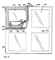
- An example of one such incubator is shown in Fig. 13.
- Incubator 282 has four compartments adapted to receive flask 202, although any number of compartments can be used and incubators can be designed to accommodate flask 2 and flask 102.
- the incubator 282 is a box-like structure having a front door 283. Each compartment is insulated with insulation material 284 and is provided with the flat base 204.
- the door 283 is attached to the body of the incubator by hinges 285.
- a handle 286 is attached to the door for ease of opening and closing the door 283.
- Upper compartment 287 shows the cell culture flask 202 positioned on the aligning ring 260 of the base 204.
- the media inlet tube 237 and media outlet tube 239 for the upper compartment 287 run along an inner wall 288 of the incubator 282 and exit from a top 289 of the incubator 282. Gas is supplied to the upper compartment 287 through the gas manifold 259. The gas enters at an entrance port 290 found on one side of the incubator 282.
- any flask according to this invention can be received by an incubator having any number of chambers.
- the incubator may require other hardware than is shown in Fig. 13 to supply to the flasks the proper cell growth gases and cell growth media and analyze the spent cell culture media and gas to monitor the cell growth in the flasks.
- Fig. 14 illustrates a cell culture system utilizing a cell culture flask having a gas permeable membrane, an incubator and means for supplying the flasks with the proper gases and media for optimum cell growth.
- This system includes a plurality of gas cylinders 304 which contain oxygen, nitrogen, carbon dioxide, or any other gas required for cell growth.
- the gas flow from the cylinders 304 is regulated by gas flow regulators 306.
- a supply line 308 from each cylinder 304 transports the gas to a multiplexer 310 where the gases are blended together as desired for a particular application.
- the gas is then transported by gas line 312 to a micropore filter unit 314 to filter the blended gas.
- the gas is then transported through gas line 316 to a gas humidifier 318.
- the humidifier 318 may also be preheated by a heater 320 to heat the incoming gas.
- the humidified gas passes through gas line 322 to a heated media receptacle 324.
- the gas is bubbled through the receptacle 324 and exits through gas line 326.
- the gas may be heated again by heater 328 in order to heat the gas to an optimum temperature for cell growth.
- the gas is supplied to an incubator 330 and distributed to each of the cell culture flasks 331.
- the media is drawn from the receptacle by a delivery pump 333, such as a peristaltic pump.
- the media then passes through transport line 334 to a media manifold 336 and then to the flasks 331 in the incubator 330.
- Spent media may also be removed from the cell culture flasks 331 through media outlet lines 338 and pass through a multi-directional valve 339 which either directs the spent media to transport line 332 for reuse or delivers the spent media to a module 340 which analyzes the chemical composition and pH of the media.
- the media is then directed by a valve 341 to either a waste disposal 342 or transported through a media transport line 344 for reuse.
- a multi-directional valve 346 can direct the spent media from transport line 344 to media transport line 332 and deposit the media into the media receptacle 322 for further use.
- the multi-directional valve 346 can also direct the media from transport line 344 to media transport line 334 and supply the media directly to the media manifold 336.
- the delivery pump 333 may be reversed to change the flow direction and purge the cell culture flasks 331 of gas or air. The purged gases are transported through the media manifold 336 and media transport line 334 and then through a purge line 348 for removal from the system.
- the flasks should be made of a transparent material, such as glass or plastic, so that an operator can observe the culture growth without taking apart the flasks.
Landscapes
- Health & Medical Sciences (AREA)
- Wood Science & Technology (AREA)
- Organic Chemistry (AREA)
- Life Sciences & Earth Sciences (AREA)
- Engineering & Computer Science (AREA)
- Bioinformatics & Cheminformatics (AREA)
- Chemical & Material Sciences (AREA)
- Zoology (AREA)
- Biomedical Technology (AREA)
- Sustainable Development (AREA)
- Microbiology (AREA)
- Biotechnology (AREA)
- Biochemistry (AREA)
- General Engineering & Computer Science (AREA)
- General Health & Medical Sciences (AREA)
- Genetics & Genomics (AREA)
- Clinical Laboratory Science (AREA)
- Apparatus Associated With Microorganisms And Enzymes (AREA)
- Micro-Organisms Or Cultivation Processes Thereof (AREA)
- Preparation Of Compounds By Using Micro-Organisms (AREA)
Priority Applications (1)
| Application Number | Priority Date | Filing Date | Title |
|---|---|---|---|
| AT88201922T ATE98988T1 (de) | 1987-09-11 | 1988-09-06 | Zellkulturkolben mit einer membranbarriere. |
Applications Claiming Priority (2)
| Application Number | Priority Date | Filing Date | Title |
|---|---|---|---|
| US07095759 US4839292B1 (en) | 1987-09-11 | 1987-09-11 | Cell culture flask utilizing membrane barrier |
| US95759 | 1993-07-21 |
Publications (3)
| Publication Number | Publication Date |
|---|---|
| EP0307048A2 true EP0307048A2 (de) | 1989-03-15 |
| EP0307048A3 EP0307048A3 (en) | 1989-10-18 |
| EP0307048B1 EP0307048B1 (de) | 1993-12-22 |
Family
ID=22253465
Family Applications (1)
| Application Number | Title | Priority Date | Filing Date |
|---|---|---|---|
| EP88201922A Expired - Lifetime EP0307048B1 (de) | 1987-09-11 | 1988-09-06 | Zellkulturkolben mit einer Membranbarriere |
Country Status (5)
| Country | Link |
|---|---|
| US (1) | US4839292B1 (de) |
| EP (1) | EP0307048B1 (de) |
| AT (1) | ATE98988T1 (de) |
| CA (1) | CA1306714C (de) |
| DE (1) | DE3886483T2 (de) |
Cited By (33)
| Publication number | Priority date | Publication date | Assignee | Title |
|---|---|---|---|---|
| FR2677664A1 (fr) * | 1991-06-13 | 1992-12-18 | Millipore Sa | Dispositif et procede de controle microbiologique des liquides sous pression. |
| EP0494333A3 (en) * | 1991-01-09 | 1993-01-13 | Becton Dickinson And Company | Multiplate subculture solid media device |
| FR2688226A1 (fr) * | 1992-03-04 | 1993-09-10 | Imedex | Dispositif de fixation d'une nappe adaptee a la culture de cellules. |
| WO1995017526A1 (de) * | 1993-12-22 | 1995-06-29 | Prenosil, Jiri, E. | Verfahren und vorrichtung zur herstellung einer zellstruktur auf einer semipermeablen membran |
| WO1996040876A1 (en) * | 1995-06-07 | 1996-12-19 | Novartis Ag | Method of expanding hematopoietic stem cells, reagents and bioreactors for use therein |
| WO1997006239A1 (de) * | 1995-08-08 | 1997-02-20 | Forschungszentrum Jülich GmbH | Vorrichtung zur serien-kultivierung von mikroorganismen bzw. zellen in begasten flüssigkeitssäulen |
| WO1997026023A1 (en) * | 1996-01-19 | 1997-07-24 | Eth, Eidgenössische Technische Hochschule Zürich | Wound dressing and apparatus |
| EP0769048A4 (de) * | 1994-06-28 | 1998-04-01 | John Wilson | Zellkulturflasche mit mehreren kammern |
| WO1998031783A1 (en) * | 1997-01-16 | 1998-07-23 | Smith & Nephew, Plc | Cell-culture system |
| EP0757097A3 (de) * | 1995-07-31 | 1998-11-04 | Becton, Dickinson and Company | Verfahren und Anlage für Ko-Kultur von Zellen |
| WO1999021960A1 (en) * | 1997-10-24 | 1999-05-06 | Oy Aboatech Ab | Method for culturing microbiological samples in a gas pressure gradient |
| FR2795089A1 (fr) * | 1999-06-17 | 2000-12-22 | Michel Thibaudon | Dispositif de controle et de regulation d'atmosphere lors de cultures microbiologiques et/ou de tests chimiques |
| NL1013649C2 (nl) * | 1998-08-03 | 2001-05-28 | Andreas Aschenbrenner | Celkweekinrichting. |
| WO2001081531A1 (fr) * | 2000-04-27 | 2001-11-01 | Cell Tissue Progress Sarl | Unite de culture de cellules et tissus a configuration variable |
| EP2474607A1 (de) * | 2005-07-26 | 2012-07-11 | Corning Incorporated | Mehrschichtige Zellkulturvorrichtung |
| WO2013057500A1 (en) * | 2011-10-21 | 2013-04-25 | Cell Medica Limited | Device for the aseptic expansion of cells |
| WO2014066483A1 (en) * | 2012-10-26 | 2014-05-01 | Corning Incorporated | Multi-layered cell culture vessel |
| WO2014179196A1 (en) * | 2013-04-30 | 2014-11-06 | Corning Incorporated | Spheroid cell culture well article and methods thereof |
| CN104379727A (zh) * | 2012-05-18 | 2015-02-25 | 威尔逊沃夫制造公司 | 改进的用于过继细胞治疗的细胞培养方法 |
| CN105392876A (zh) * | 2013-06-24 | 2016-03-09 | 威尔逊沃夫制造公司 | 用于透气性细胞培养过程的封闭系统装置和方法 |
| US9567565B2 (en) | 2009-12-08 | 2017-02-14 | Juan F. Vera | Methods of cell culture for adoptive cell therapy |
| CN109810899A (zh) * | 2019-04-09 | 2019-05-28 | 苏州赛普生物科技有限公司 | 悬浮细胞培养瓶 |
| US11345880B2 (en) | 2017-07-14 | 2022-05-31 | Corning Incorporated | 3D cell culture vessels for manual or automatic media exchange |
| US11584906B2 (en) | 2017-07-14 | 2023-02-21 | Corning Incorporated | Cell culture vessel for 3D culture and methods of culturing 3D cells |
| US11613722B2 (en) | 2014-10-29 | 2023-03-28 | Corning Incorporated | Perfusion bioreactor platform |
| US11661574B2 (en) | 2018-07-13 | 2023-05-30 | Corning Incorporated | Fluidic devices including microplates with interconnected wells |
| US11732227B2 (en) | 2018-07-13 | 2023-08-22 | Corning Incorporated | Cell culture vessels with stabilizer devices |
| US11767499B2 (en) | 2017-07-14 | 2023-09-26 | Corning Incorporated | Cell culture vessel |
| US11857970B2 (en) | 2017-07-14 | 2024-01-02 | Corning Incorporated | Cell culture vessel |
| US11912968B2 (en) | 2018-07-13 | 2024-02-27 | Corning Incorporated | Microcavity dishes with sidewall including liquid medium delivery surface |
| US11976263B2 (en) | 2014-10-29 | 2024-05-07 | Corning Incorporated | Cell culture insert |
| US20250011701A1 (en) * | 2021-10-29 | 2025-01-09 | Nextern Innovation, Llc | Cell culture system with controlled gas transfer boundary conditions |
| US12203059B2 (en) | 2014-10-29 | 2025-01-21 | Corning Incorporated | Microwell design and fabrication for generation of cell culture aggregates |
Families Citing this family (93)
| Publication number | Priority date | Publication date | Assignee | Title |
|---|---|---|---|---|
| US5213981A (en) * | 1988-09-27 | 1993-05-25 | Kabushiki Kaisha Komatsu Seisakusho | Bedding apparatus |
| US5763266A (en) * | 1989-06-15 | 1998-06-09 | The Regents Of The University Of Michigan | Methods, compositions and devices for maintaining and growing human stem and/or hematopoietics cells |
| US5227137A (en) * | 1991-04-04 | 1993-07-13 | Nicholson Precision Instruments Inc. | Vacuum clamped multi-sample filtration apparatus |
| GB2268187A (en) * | 1992-07-01 | 1994-01-05 | Univ Hull | Cell culture vessels |
| US5707869A (en) * | 1994-06-28 | 1998-01-13 | Wolf; Martin L. | Compartmentalized multiple well tissue culture plate |
| US5714384A (en) * | 1994-06-28 | 1998-02-03 | Wilson; John R. | Compartmentalized tissue culture bag |
| US5693537A (en) * | 1994-06-28 | 1997-12-02 | Wilson; John R. | Compartmentalized tissue culture flask |
| USD414272S (en) | 1994-07-06 | 1999-09-21 | Biomerieux Vitek, Inc. | Biochemical card for use in automated microbial machines |
| US5482854A (en) * | 1994-10-06 | 1996-01-09 | Becton, Dickinson And Company | Growth environment assembly and method of use thereof |
| US6297046B1 (en) | 1994-10-28 | 2001-10-02 | Baxter International Inc. | Multilayer gas-permeable container for the culture of adherent and non-adherent cells |
| US5935847A (en) | 1994-10-28 | 1999-08-10 | Baxter International Inc. | Multilayer gas-permeable container for the culture of adherent and non-adherent cells |
| US6133019A (en) * | 1995-03-28 | 2000-10-17 | Kinetic Biosystems, Inc. | Centrifugal fermentation process |
| US5622819A (en) * | 1995-03-28 | 1997-04-22 | Kinetic Biosystems, Inc. | Centrifugal fermentation process |
| US6214617B1 (en) | 1995-03-28 | 2001-04-10 | Kinetic Biosystems, Inc. | Centrifugal fermentation process |
| US6660509B1 (en) | 1995-03-28 | 2003-12-09 | Kinetic Biosystems, Inc. | Methods and devices for remediation and fermentation |
| US20050266548A1 (en) * | 1995-03-28 | 2005-12-01 | Kbi Biopharma, Inc. | Biocatalyst chamber encapsulation system for bioremediation and fermentation with improved rotor |
| US6916652B2 (en) * | 1995-03-28 | 2005-07-12 | Kinetic Biosystems, Inc. | Biocatalyst chamber encapsulation system for bioremediation and fermentation |
| CA2220968C (en) * | 1995-06-05 | 2008-01-29 | Akzo Nobel Nv | Device and method for detecting microorganisms |
| US6096532A (en) * | 1995-06-07 | 2000-08-01 | Aastrom Biosciences, Inc. | Processor apparatus for use in a system for maintaining and growing biological cells |
| US6391404B1 (en) | 1995-06-07 | 2002-05-21 | Baxter International Inc. | Coextruded multilayer film materials and containers made therefrom |
| US6228635B1 (en) | 1995-06-07 | 2001-05-08 | Aastrom Bioscience, Inc. | Portable cell growth cassette for use in maintaining and growing biological cells |
| US6238908B1 (en) | 1995-06-07 | 2001-05-29 | Aastrom Biosciences, Inc. | Apparatus and method for maintaining and growth biological cells |
| US5985653A (en) * | 1995-06-07 | 1999-11-16 | Aastrom Biosciences, Inc. | Incubator apparatus for use in a system for maintaining and growing biological cells |
| US6024220A (en) | 1995-06-07 | 2000-02-15 | Baxter International Inc. | Encapsulated seam for multilayer materials |
| CA2229846C (en) * | 1996-07-03 | 2006-05-30 | Baxter International Inc. | Method of sealing a port tube in a container |
| FR2762092B1 (fr) | 1997-04-15 | 1999-05-28 | Bio Merieux | Procede et dispositif de remplissage avec un milieu liquide d'une carte d'analyse |
| GB9808836D0 (en) * | 1998-04-27 | 1998-06-24 | Amersham Pharm Biotech Uk Ltd | Microfabricated apparatus for cell based assays |
| US6673008B1 (en) | 1998-04-28 | 2004-01-06 | Ronald J. Thompson | Fallopian tube and method of in vitro fertilization and embryo development |
| US6645759B2 (en) | 1998-12-04 | 2003-11-11 | Flexcell International Corporation | Apparatus for growing cells in culture under shear stress and/or strain |
| US6586235B1 (en) | 1998-12-04 | 2003-07-01 | Flexcell International Corporation | Apparatus for growing cells in culture under shear stress and/or strain |
| US6095356A (en) * | 1999-03-10 | 2000-08-01 | Children's Medical Center Corp. | Vented flask cap for absorbing radioactive gases |
| US6703217B2 (en) | 2000-01-31 | 2004-03-09 | Kinetic Biosystems, Inc. | Methods and devices for remediation and fermentation |
| US6617151B1 (en) * | 2000-02-29 | 2003-09-09 | Gore Enterprise Holdings, Inc. | Method of closing a cell containment device with a wet seal |
| US7485454B1 (en) * | 2000-03-10 | 2009-02-03 | Bioprocessors Corp. | Microreactor |
| US6653124B1 (en) | 2000-11-10 | 2003-11-25 | Cytoplex Biosciences Inc. | Array-based microenvironment for cell culturing, cell monitoring and drug-target validation |
| US20030060695A1 (en) * | 2001-03-07 | 2003-03-27 | Connelly Patrick R. | Implantable artificial organ devices |
| US7244232B2 (en) * | 2001-03-07 | 2007-07-17 | Biomed Solutions, Llc | Process for identifying cancerous and/or metastatic cells of a living organism |
| US20040058437A1 (en) * | 2001-04-10 | 2004-03-25 | Rodgers Seth T. | Materials and reactor systems having humidity and gas control |
| US20040058407A1 (en) * | 2001-04-10 | 2004-03-25 | Miller Scott E. | Reactor systems having a light-interacting component |
| WO2002083852A2 (en) * | 2001-04-10 | 2002-10-24 | Bioprocessors Corporation | Microfermentor device and cell based screening method |
| US20050026134A1 (en) * | 2002-04-10 | 2005-02-03 | Bioprocessors Corp. | Systems and methods for control of pH and other reactor environment conditions |
| US7300789B2 (en) * | 2002-05-21 | 2007-11-27 | L'oreal | Bioreactor forming a rigid vessel |
| IL166340A0 (en) * | 2002-07-18 | 2006-01-16 | Kemire Phosphates Pty Ltd | Proliferation and delivery apparatus |
| US20050170491A1 (en) * | 2002-07-31 | 2005-08-04 | Mutsumi Takagi | Automatic culture apparatus for cell or tisse with biological origin |
| US20060019375A1 (en) * | 2002-09-16 | 2006-01-26 | Josef Seidl | Device for culturing cells, particularly human or animal cells |
| DE50211123D1 (de) * | 2002-09-16 | 2007-12-06 | Pan Biotech Gmbh | Verfahren zur kultivierung von zellen, insbesondere menschlicher oder tierischer zellen |
| US20050266547A1 (en) * | 2002-09-16 | 2005-12-01 | Wilhelm Scherze | Cell culture chamber for a cell culture system |
| JP2004113153A (ja) * | 2002-09-27 | 2004-04-15 | Sanyo Electric Co Ltd | Co2インキュベータ |
| US7759115B2 (en) * | 2003-02-10 | 2010-07-20 | Bio X Cell, Inc. | Incubation and/or storage container system and method |
| EP1628748A2 (de) * | 2003-06-05 | 2006-03-01 | Bioprocessors Corporation | Reaktor mit speicherkomponente |
| US20050074873A1 (en) * | 2003-09-09 | 2005-04-07 | Shanler Michael S. | Tissue culture vessel |
| CN101120083B (zh) | 2003-10-08 | 2013-03-27 | 威尔森沃尔夫制造公司 | 利用透气性材料进行细胞培养的方法及装置 |
| US7078228B2 (en) * | 2003-12-31 | 2006-07-18 | Corning Incorporated | Cell cultivating flask |
| JP2008504845A (ja) * | 2004-06-07 | 2008-02-21 | バイオプロセッサーズ コーポレイション | リアクター環境条件の制御 |
| JP4563782B2 (ja) * | 2004-11-26 | 2010-10-13 | 株式会社日立製作所 | 培養装置 |
| US7906324B2 (en) * | 2005-05-12 | 2011-03-15 | The Board Of Trustees Of The University Of Alabama | Apparatus and method for incubating cell cultures |
| US7745210B2 (en) * | 2006-06-30 | 2010-06-29 | Corning Incorporated | Fluid flow diverter for cell culture vessel |
| WO2008054825A2 (en) | 2006-11-03 | 2008-05-08 | Aastrom Biosciences, Inc. | Mixed cell populations for tissue repair and separation technique for cell processing |
| JP2010512149A (ja) * | 2006-12-07 | 2010-04-22 | ウィルソン ウォルフ マニュファクチャリング コーポレイション | 細胞培養に効果的な装置および方法 |
| US7897379B2 (en) * | 2007-02-26 | 2011-03-01 | Corning Incorporated | Device and method for reducing bubble formation in cell culture |
| US9309491B2 (en) | 2007-05-29 | 2016-04-12 | Corning Incorporated | Cell culture apparatus for co-culture of cells |
| US8177082B2 (en) * | 2008-04-18 | 2012-05-15 | Corning Incorporated | Flexible membrane valve for cell culture vessel |
| CA2730104A1 (en) * | 2008-07-08 | 2010-01-14 | Wilson Wolf Manufacturing Corporation | Improved gas permeable cell culture device and method of use |
| US8513015B2 (en) * | 2010-06-11 | 2013-08-20 | Corning Incorporated | Laminin-entactin complex and cell culture article and methods thereof |
| DK2606116T3 (da) | 2010-08-18 | 2020-08-03 | Drugmode Aps | Bioreaktorsystem |
| WO2012065122A2 (en) * | 2010-11-12 | 2012-05-18 | Abbott Laboratories | High throughput, optical method and system for determining the effect of a test substance on living cells |
| WO2012079577A1 (en) * | 2010-12-15 | 2012-06-21 | Drugmode Aps | Bioreactor with lid for easy access to incubation cavity |
| GB201104206D0 (en) * | 2011-03-14 | 2011-04-27 | Ge Healthcare Uk Ltd | Biological sample holder and method of assembling same |
| US20130337565A1 (en) | 2012-06-19 | 2013-12-19 | Medtrain Technologies, Llc | Method and Apparatus for Patterning Cells |
| CN114106988A (zh) | 2012-10-26 | 2022-03-01 | 麻省理工学院 | 化学反应器中的湿度控制 |
| EP3036317A4 (de) | 2013-08-23 | 2017-04-12 | Massachusetts Institute of Technology | Kleinvolumige bioreaktoren mit im wesentlichen konstanten arbeitsvolumina sowie entsprechende systeme und verfahren |
| DE102014214077A1 (de) * | 2014-07-18 | 2016-01-21 | Hamilton Bonaduz Ag | Laborbehälter, insbesondere Zellkulturbehälter, mit einer in das Behältervolumen hinein verlaufenden Gas-Ausgleichsleitung |
| CN105296341A (zh) * | 2015-11-30 | 2016-02-03 | 苏州钧隆塑胶有限公司 | 一种高效导管养菌瓶 |
| US10813342B2 (en) | 2016-05-10 | 2020-10-27 | Excet Incorporated | Methods of using training aid delivery devices (TADD) |
| WO2018195014A1 (en) * | 2017-04-19 | 2018-10-25 | Neubiser Richard | Bioreactor for biological material |
| DE102018122745B3 (de) * | 2018-09-17 | 2019-12-19 | Naturin Viscofan Gmbh | Vorrichtung zur Medienzufuhr oder -abfuhr, Kulturgefäß mit einer solchen Vorrichtung und Verfahren zur Kultivierung von mikrobiologischen Systemen unter Verwendung eines solchen Kulturgefäßes |
| TWI671399B (zh) * | 2018-10-22 | 2019-09-11 | 國立清華大學 | 細胞培養裝置及細胞培養系統 |
| CN109609379A (zh) * | 2019-01-21 | 2019-04-12 | 英诺维尔智能科技(苏州)有限公司 | 一种新型双侧透气型培养瓶 |
| US20200308532A1 (en) * | 2019-03-29 | 2020-10-01 | Fenwal, Inc. | Automated Systems and Methods for Cell Culturing |
| JP7791096B2 (ja) | 2020-03-10 | 2025-12-23 | セラレス コーポレーション | 細胞処理のためのシステム、デバイス、及び方法 |
| CN111206014B (zh) * | 2020-04-01 | 2024-06-14 | 中国烟草总公司郑州烟草研究院 | 一种仿生肺泡培养方法及培养装置 |
| CN112369405B (zh) * | 2020-10-19 | 2021-12-07 | 广东博工三六五机器人信息技术有限公司 | 一种可无菌运送细胞的培养箱 |
| DE102022133343A1 (de) | 2021-12-15 | 2023-06-15 | Idex Health & Science Llc | Automatisierte probenvorbereitung zur analyse von verbrauchtem medium |
| EP4683997A2 (de) | 2023-03-21 | 2026-01-28 | Cellares Corporation | Systeme, vorrichtungen und verfahren zur elektroporation in einem zellverarbeitungssystem |
| US12399193B2 (en) | 2023-05-05 | 2025-08-26 | Cellares Corporation | Systems, devices, and methods for combined cell processes |
| EP4735577A2 (de) | 2023-06-30 | 2026-05-06 | Cellares Corporation | Systeme, vorrichtungen und verfahren für flüssigkeitstransfer in einem automatisierten zellverarbeitungssystem |
| EP4766808A1 (de) | 2023-08-21 | 2026-07-01 | Cellares Corporation | Bioreaktoren und verfahren zu deren verwendung in automatischen zellverarbeitungssystemen |
| US12337321B2 (en) | 2023-08-21 | 2025-06-24 | Cellares Corporation | Systems, devices, and methods for automatic cell sorting |
| EP4766812A1 (de) | 2023-08-21 | 2026-07-01 | Cellares Corporation | Systeme, vorrichtungen und verfahren zur flüssigkeitssteuerung in einem zellverarbeitungssystem |
| CN116814432B (zh) * | 2023-08-29 | 2023-11-24 | 苏州赛普生物科技股份有限公司 | 一种高透气性的细胞封闭培养装置及方法 |
| US12492368B2 (en) | 2024-03-11 | 2025-12-09 | Cellares Corporation | Monitoring air pressure within a cell processing system |
| WO2025202944A2 (en) | 2024-03-27 | 2025-10-02 | Cellares Corporation | Liquid level and flow rate detection within a cell processing system |
| USD1109621S1 (en) | 2024-04-15 | 2026-01-20 | Cellares Corporation | Analytical platform for biological material testing |
Family Cites Families (20)
| Publication number | Priority date | Publication date | Assignee | Title |
|---|---|---|---|---|
| DE839245C (de) * | 1949-04-15 | 1952-05-19 | Ewald Dr Med Kanz | Verfahren und Einrichtung zur Zuechtung von Kleinlebewesen |
| US3407120A (en) * | 1965-12-23 | 1968-10-22 | Abbott Lab | Tissue culture propagator and method |
| US3537956A (en) * | 1967-06-26 | 1970-11-03 | Joseph R Falcone | Petrie dish |
| US3449210A (en) * | 1967-08-22 | 1969-06-10 | Baltimore Biolog Lab | Microorganism culturing assembly |
| US3941662A (en) * | 1971-06-09 | 1976-03-02 | Max-Planck-Gesellschaft Zur Forderung Der Wissenschaften E.V. | Apparatus for culturing cells |
| US3821087A (en) * | 1972-05-18 | 1974-06-28 | Dedrick R | Cell culture on semi-permeable tubular membranes |
| US3870602A (en) * | 1973-04-30 | 1975-03-11 | California Lab Ind Inc | Gas permeable sterile culture bottle |
| US4033825A (en) * | 1973-05-31 | 1977-07-05 | Instrumentation Laboratory, Inc. | Cell culture system |
| JPS5238082A (en) * | 1975-09-13 | 1977-03-24 | Heraeus Gmbh W C | Cultivating container for microorganism * bacterium and tissue |
| US4201845A (en) * | 1976-04-12 | 1980-05-06 | Monsanto Company | Cell culture reactor |
| DE2726313C3 (de) * | 1977-06-10 | 1980-02-07 | Battelle-Institut E.V., 6000 Frankfurt | Verfahren zur in-vitro-Biosynthese von Hormonen, insbesondere von Insulin |
| US4228243A (en) * | 1978-07-13 | 1980-10-14 | Toray Industries, Inc. | Cell culture propagation apparatus |
| US4208483A (en) * | 1978-09-21 | 1980-06-17 | The University Of Toledo | Tissue culture system |
| US4296205A (en) * | 1980-02-22 | 1981-10-20 | Verma Dharmvir S | Cell culture and continuous dialysis flask and method |
| US4440853A (en) * | 1980-08-21 | 1984-04-03 | Board Of Trustees Of The Leland Stanford Junior University | Microbiological methods using hollow fiber membrane reactor |
| US4334028A (en) * | 1981-01-02 | 1982-06-08 | Carver Joseph L | Flask |
| US4416993A (en) * | 1981-06-11 | 1983-11-22 | Mcleod & Miller (Engineers) Limited | Apparatus with semi-permeable membrane, and method for cultivating micro-organisms |
| US4559299A (en) * | 1983-02-04 | 1985-12-17 | Brown University Research Foundation Inc. | Cytotoxicity assays in cell culturing devices |
| US4634676A (en) * | 1984-06-06 | 1987-01-06 | Becton, Dickinson And Company | Replica plating device |
| DE3600487A1 (de) * | 1986-01-10 | 1987-07-16 | Gebhardt Rolf | Perifusionsgeraet fuer die zuechtung lebender zellen und verfahren zur perifusions-kultivierung |
-
1987
- 1987-09-11 US US07095759 patent/US4839292B1/en not_active Expired - Fee Related
-
1988
- 1988-09-06 AT AT88201922T patent/ATE98988T1/de not_active IP Right Cessation
- 1988-09-06 EP EP88201922A patent/EP0307048B1/de not_active Expired - Lifetime
- 1988-09-06 DE DE3886483T patent/DE3886483T2/de not_active Expired - Lifetime
- 1988-09-07 CA CA000577082A patent/CA1306714C/en not_active Expired - Lifetime
Cited By (68)
| Publication number | Priority date | Publication date | Assignee | Title |
|---|---|---|---|---|
| EP0494333A3 (en) * | 1991-01-09 | 1993-01-13 | Becton Dickinson And Company | Multiplate subculture solid media device |
| EP0536004A1 (de) * | 1991-06-13 | 1993-04-07 | Millipore S.A. | Verfahren und Anlage für die mikrobiologische Untersuchung von Flüssigkeiten |
| FR2677664A1 (fr) * | 1991-06-13 | 1992-12-18 | Millipore Sa | Dispositif et procede de controle microbiologique des liquides sous pression. |
| FR2688226A1 (fr) * | 1992-03-04 | 1993-09-10 | Imedex | Dispositif de fixation d'une nappe adaptee a la culture de cellules. |
| WO1995017526A1 (de) * | 1993-12-22 | 1995-06-29 | Prenosil, Jiri, E. | Verfahren und vorrichtung zur herstellung einer zellstruktur auf einer semipermeablen membran |
| EP0769048A4 (de) * | 1994-06-28 | 1998-04-01 | John Wilson | Zellkulturflasche mit mehreren kammern |
| WO1996040876A1 (en) * | 1995-06-07 | 1996-12-19 | Novartis Ag | Method of expanding hematopoietic stem cells, reagents and bioreactors for use therein |
| EP0757097A3 (de) * | 1995-07-31 | 1998-11-04 | Becton, Dickinson and Company | Verfahren und Anlage für Ko-Kultur von Zellen |
| WO1997006239A1 (de) * | 1995-08-08 | 1997-02-20 | Forschungszentrum Jülich GmbH | Vorrichtung zur serien-kultivierung von mikroorganismen bzw. zellen in begasten flüssigkeitssäulen |
| US6063618A (en) * | 1995-08-08 | 2000-05-16 | Forschungszentrum Julich Gmbh | Device for the series cultivation of micro-organisms or cells in gasified liquid columns |
| WO1997026023A1 (en) * | 1996-01-19 | 1997-07-24 | Eth, Eidgenössische Technische Hochschule Zürich | Wound dressing and apparatus |
| WO1998031783A1 (en) * | 1997-01-16 | 1998-07-23 | Smith & Nephew, Plc | Cell-culture system |
| WO1999021960A1 (en) * | 1997-10-24 | 1999-05-06 | Oy Aboatech Ab | Method for culturing microbiological samples in a gas pressure gradient |
| NL1013649C2 (nl) * | 1998-08-03 | 2001-05-28 | Andreas Aschenbrenner | Celkweekinrichting. |
| FR2801899A1 (fr) * | 1998-08-03 | 2001-06-08 | Acm Biotech Gmbh | Dispositif destine a la culture de cellules |
| US6329195B1 (en) | 1998-08-03 | 2001-12-11 | Acm-Biotech Gmbh | Cell culture apparatus |
| FR2795089A1 (fr) * | 1999-06-17 | 2000-12-22 | Michel Thibaudon | Dispositif de controle et de regulation d'atmosphere lors de cultures microbiologiques et/ou de tests chimiques |
| WO2001081531A1 (fr) * | 2000-04-27 | 2001-11-01 | Cell Tissue Progress Sarl | Unite de culture de cellules et tissus a configuration variable |
| FR2808283A1 (fr) * | 2000-04-27 | 2001-11-02 | Cell Tissue Progress | Unite de culture de cellules et tissus a configuration variable |
| US6475777B1 (en) | 2000-04-27 | 2002-11-05 | Cell Tissue Progress | Cell and tissue culture unit with variable configuration |
| EP2474607A1 (de) * | 2005-07-26 | 2012-07-11 | Corning Incorporated | Mehrschichtige Zellkulturvorrichtung |
| US11905506B2 (en) | 2005-07-26 | 2024-02-20 | Corning Incorporated | Multilayered cell culture apparatus |
| US11274273B2 (en) | 2005-07-26 | 2022-03-15 | Corning Incorporated | Multilayered cell culture apparatus |
| US9845451B2 (en) | 2005-07-26 | 2017-12-19 | Corning Incorporated | Multilayered cell culture apparatus |
| US12454667B2 (en) | 2009-12-08 | 2025-10-28 | Wilson Wolf Manufacturing, LLC | Methods of cell culture for adoptive cell therapy |
| US11999969B2 (en) | 2009-12-08 | 2024-06-04 | Wilson Wolf Manufacturing | Methods of cell culture for adoptive cell therapy |
| US11268066B2 (en) | 2009-12-08 | 2022-03-08 | Wilson Wolf Manufacturing | Methods of cell culture for adoptive cell therapy |
| US10533156B2 (en) | 2009-12-08 | 2020-01-14 | Baylor College Of Medicine | Methods of cell culture for adoptive cell therapy |
| US9567565B2 (en) | 2009-12-08 | 2017-02-14 | Juan F. Vera | Methods of cell culture for adoptive cell therapy |
| US10221391B2 (en) | 2011-10-21 | 2019-03-05 | Cell Medica Limited | Device for the aseptic expansion of cells |
| US9315774B2 (en) | 2011-10-21 | 2016-04-19 | Cell Medica Limited | Device for the aseptic expansion of cells |
| JP2014530618A (ja) * | 2011-10-21 | 2014-11-20 | セル・メディカ・リミテッド | 細胞の無菌増殖のための装置 |
| WO2013057500A1 (en) * | 2011-10-21 | 2013-04-25 | Cell Medica Limited | Device for the aseptic expansion of cells |
| CN104379727A (zh) * | 2012-05-18 | 2015-02-25 | 威尔逊沃夫制造公司 | 改进的用于过继细胞治疗的细胞培养方法 |
| EP2850175B1 (de) | 2012-05-18 | 2020-12-16 | Wilson Wolf Manufacturing Corporation | Verbesserte verfahren für zellkulturen für adoptive zelltherapien |
| AU2013262485B2 (en) * | 2012-05-18 | 2017-12-14 | Wilson Wolf Manufacturing, LLC | Improved methods of cell culture for adoptive cell therapy |
| AU2020200037B2 (en) * | 2012-05-18 | 2022-03-31 | Wilson Wolf Manufacturing, LLC | Improved methods of cell culture for adoptive cell therapy |
| EP2850175A4 (de) * | 2012-05-18 | 2015-12-16 | Wolf Wilson Mfg Corp | Verbesserte verfahren für zellkulturen für adoptive zelltherapien |
| EP3800242A1 (de) * | 2012-05-18 | 2021-04-07 | Wilson Wolf Manufacturing Corporation | Verbesserte verfahren zur zellkultivierung für adoptive zelltherapie |
| WO2014066483A1 (en) * | 2012-10-26 | 2014-05-01 | Corning Incorporated | Multi-layered cell culture vessel |
| JP2019162134A (ja) * | 2013-04-30 | 2019-09-26 | コーニング インコーポレイテッド | スフェロイド細胞培養ウェル製品およびその方法 |
| EP3633022A1 (de) * | 2013-04-30 | 2020-04-08 | Corning Incorporated | Well-artikel und perfusionsplattenvorrichtung zur sphäroidzellkultur |
| WO2014179196A1 (en) * | 2013-04-30 | 2014-11-06 | Corning Incorporated | Spheroid cell culture well article and methods thereof |
| US9790465B2 (en) | 2013-04-30 | 2017-10-17 | Corning Incorporated | Spheroid cell culture well article and methods thereof |
| US12146154B2 (en) | 2013-04-30 | 2024-11-19 | Corning Incorporated | Spheroid cell culture article and methods thereof |
| US11441121B2 (en) | 2013-04-30 | 2022-09-13 | Corning Incorporated | Spheroid cell culture article and methods thereof |
| JP2016520307A (ja) * | 2013-04-30 | 2016-07-14 | コーニング インコーポレイテッド | スフェロイド細胞培養ウェル製品およびその方法 |
| CN105392876A (zh) * | 2013-06-24 | 2016-03-09 | 威尔逊沃夫制造公司 | 用于透气性细胞培养过程的封闭系统装置和方法 |
| CN105392876B (zh) * | 2013-06-24 | 2019-07-23 | 威尔逊沃夫制造公司 | 用于透气性细胞培养过程的封闭系统装置和方法 |
| US11613722B2 (en) | 2014-10-29 | 2023-03-28 | Corning Incorporated | Perfusion bioreactor platform |
| US12203059B2 (en) | 2014-10-29 | 2025-01-21 | Corning Incorporated | Microwell design and fabrication for generation of cell culture aggregates |
| US12624327B2 (en) | 2014-10-29 | 2026-05-12 | Corning Incorporated | Cell culture insert |
| US11667874B2 (en) | 2014-10-29 | 2023-06-06 | Corning Incorporated | Perfusion bioreactor platform |
| US11976263B2 (en) | 2014-10-29 | 2024-05-07 | Corning Incorporated | Cell culture insert |
| US11767499B2 (en) | 2017-07-14 | 2023-09-26 | Corning Incorporated | Cell culture vessel |
| US11857970B2 (en) | 2017-07-14 | 2024-01-02 | Corning Incorporated | Cell culture vessel |
| US12311374B2 (en) | 2017-07-14 | 2025-05-27 | Corning Incorporated | Cell culture vessel |
| US11970682B2 (en) | 2017-07-14 | 2024-04-30 | Corning Incorporated | 3D cell culture vessels for manual or automatic media exchange |
| US11584906B2 (en) | 2017-07-14 | 2023-02-21 | Corning Incorporated | Cell culture vessel for 3D culture and methods of culturing 3D cells |
| US11345880B2 (en) | 2017-07-14 | 2022-05-31 | Corning Incorporated | 3D cell culture vessels for manual or automatic media exchange |
| US11661574B2 (en) | 2018-07-13 | 2023-05-30 | Corning Incorporated | Fluidic devices including microplates with interconnected wells |
| US12270017B2 (en) | 2018-07-13 | 2025-04-08 | Corning Incorporated | Cell culture vessels with stabilizer devices |
| US11912968B2 (en) | 2018-07-13 | 2024-02-27 | Corning Incorporated | Microcavity dishes with sidewall including liquid medium delivery surface |
| US12448594B2 (en) | 2018-07-13 | 2025-10-21 | Corning Incorporated | Fluidic devices including microplates with interconnected wells |
| US11732227B2 (en) | 2018-07-13 | 2023-08-22 | Corning Incorporated | Cell culture vessels with stabilizer devices |
| CN109810899A (zh) * | 2019-04-09 | 2019-05-28 | 苏州赛普生物科技有限公司 | 悬浮细胞培养瓶 |
| US20250011701A1 (en) * | 2021-10-29 | 2025-01-09 | Nextern Innovation, Llc | Cell culture system with controlled gas transfer boundary conditions |
| US12460166B2 (en) * | 2021-10-29 | 2025-11-04 | Nextern Innovation, Llc | Cell culture system with controlled gas transfer boundary conditions |
Also Published As
| Publication number | Publication date |
|---|---|
| EP0307048B1 (de) | 1993-12-22 |
| EP0307048A3 (en) | 1989-10-18 |
| US4839292A (en) | 1989-06-13 |
| CA1306714C (en) | 1992-08-25 |
| DE3886483D1 (de) | 1994-02-03 |
| DE3886483T2 (de) | 1994-07-14 |
| US4839292B1 (en) | 1994-09-13 |
| ATE98988T1 (de) | 1994-01-15 |
Similar Documents
| Publication | Publication Date | Title |
|---|---|---|
| EP0307048B1 (de) | Zellkulturkolben mit einer Membranbarriere | |
| JP4108816B2 (ja) | 培養容器アセンブリ、これに用いる蓋およびこれを用いた細胞培養方法 | |
| US11905506B2 (en) | Multilayered cell culture apparatus | |
| US5139951A (en) | Culture device having a detachable cell or tissue growth surface | |
| EP0866119B1 (de) | Vorrichtung zur Zellkultur und ihre Anwendung in einem Verfahren zur Kultur von Zellen | |
| EP0552308B1 (de) | Kulturvorrichtung mit lösbarer aufwuchsfläche für zellen oder gewebe | |
| JP4126109B2 (ja) | 培養容器アセンブリ、これに用いる蓋およびこれを用いた細胞培養方法 | |
| EP0866122B1 (de) | Wachstumsvorrichtung und Verfahren für seine Anwendung | |
| EP0764718B1 (de) | In vitrozellkultur-System | |
| US5554536A (en) | Biological analysis device having improved contamination prevention | |
| US5578490A (en) | Cell culture plate with a system for lateral diffusion of molecules through a barrier membrane | |
| US4296205A (en) | Cell culture and continuous dialysis flask and method | |
| US20020039785A1 (en) | Cell-culture vessel | |
| US6063618A (en) | Device for the series cultivation of micro-organisms or cells in gasified liquid columns | |
| US8323957B2 (en) | Device and method for the incubation of cells | |
| US6284531B1 (en) | Multi-compartment device for cultivating microorganisms | |
| JPH11509420A (ja) | 透析式マルチプルウエル組織培養プレート | |
| JP2006204263A (ja) | 培養容器および培養方法 |
Legal Events
| Date | Code | Title | Description |
|---|---|---|---|
| PUAI | Public reference made under article 153(3) epc to a published international application that has entered the european phase |
Free format text: ORIGINAL CODE: 0009012 |
|
| AK | Designated contracting states |
Kind code of ref document: A2 Designated state(s): AT BE CH DE ES FR GB GR IT LI LU NL SE |
|
| PUAL | Search report despatched |
Free format text: ORIGINAL CODE: 0009013 |
|
| RHK1 | Main classification (correction) |
Ipc: C12M 1/12 |
|
| AK | Designated contracting states |
Kind code of ref document: A3 Designated state(s): AT BE CH DE ES FR GB GR IT LI LU NL SE |
|
| 17P | Request for examination filed |
Effective date: 19900403 |
|
| 17Q | First examination report despatched |
Effective date: 19920127 |
|
| GRAA | (expected) grant |
Free format text: ORIGINAL CODE: 0009210 |
|
| AK | Designated contracting states |
Kind code of ref document: B1 Designated state(s): AT BE CH DE ES FR GB GR IT LI LU NL SE |
|
| PG25 | Lapsed in a contracting state [announced via postgrant information from national office to epo] |
Ref country code: GR Free format text: LAPSE BECAUSE OF FAILURE TO SUBMIT A TRANSLATION OF THE DESCRIPTION OR TO PAY THE FEE WITHIN THE PRESCRIBED TIME-LIMIT Effective date: 19931222 Ref country code: NL Effective date: 19931222 Ref country code: SE Effective date: 19931222 Ref country code: ES Free format text: THE PATENT HAS BEEN ANNULLED BY A DECISION OF A NATIONAL AUTHORITY Effective date: 19931222 |
|
| REF | Corresponds to: |
Ref document number: 98988 Country of ref document: AT Date of ref document: 19940115 Kind code of ref document: T |
|
| REF | Corresponds to: |
Ref document number: 3886483 Country of ref document: DE Date of ref document: 19940203 |
|
| ITF | It: translation for a ep patent filed | ||
| ET | Fr: translation filed | ||
| NLV1 | Nl: lapsed or annulled due to failure to fulfill the requirements of art. 29p and 29m of the patents act | ||
| PLBE | No opposition filed within time limit |
Free format text: ORIGINAL CODE: 0009261 |
|
| STAA | Information on the status of an ep patent application or granted ep patent |
Free format text: STATUS: NO OPPOSITION FILED WITHIN TIME LIMIT |
|
| 26N | No opposition filed | ||
| REG | Reference to a national code |
Ref country code: GB Ref legal event code: IF02 |
|
| PGFP | Annual fee paid to national office [announced via postgrant information from national office to epo] |
Ref country code: AT Payment date: 20020911 Year of fee payment: 15 |
|
| PGFP | Annual fee paid to national office [announced via postgrant information from national office to epo] |
Ref country code: LU Payment date: 20020918 Year of fee payment: 15 |
|
| PGFP | Annual fee paid to national office [announced via postgrant information from national office to epo] |
Ref country code: BE Payment date: 20021129 Year of fee payment: 15 |
|
| PG25 | Lapsed in a contracting state [announced via postgrant information from national office to epo] |
Ref country code: AT Free format text: LAPSE BECAUSE OF NON-PAYMENT OF DUE FEES Effective date: 20030906 Ref country code: LU Free format text: LAPSE BECAUSE OF NON-PAYMENT OF DUE FEES Effective date: 20030906 |
|
| PG25 | Lapsed in a contracting state [announced via postgrant information from national office to epo] |
Ref country code: BE Free format text: LAPSE BECAUSE OF NON-PAYMENT OF DUE FEES Effective date: 20030930 |
|
| BERE | Be: lapsed |
Owner name: *CREMONESE JOSEPH GUY Effective date: 20030930 |
|
| PGFP | Annual fee paid to national office [announced via postgrant information from national office to epo] |
Ref country code: DE Payment date: 20070830 Year of fee payment: 20 |
|
| PGFP | Annual fee paid to national office [announced via postgrant information from national office to epo] |
Ref country code: CH Payment date: 20070830 Year of fee payment: 20 |
|
| PGFP | Annual fee paid to national office [announced via postgrant information from national office to epo] |
Ref country code: GB Payment date: 20070905 Year of fee payment: 20 |
|
| PGFP | Annual fee paid to national office [announced via postgrant information from national office to epo] |
Ref country code: IT Payment date: 20070926 Year of fee payment: 20 |
|
| PGFP | Annual fee paid to national office [announced via postgrant information from national office to epo] |
Ref country code: FR Payment date: 20070914 Year of fee payment: 20 |
|
| REG | Reference to a national code |
Ref country code: CH Ref legal event code: PL |
|
| REG | Reference to a national code |
Ref country code: GB Ref legal event code: PE20 Expiry date: 20080905 |
|
| PG25 | Lapsed in a contracting state [announced via postgrant information from national office to epo] |
Ref country code: GB Free format text: LAPSE BECAUSE OF EXPIRATION OF PROTECTION Effective date: 20080905 |