EP0307080B1 - Fahrzeugscheibenbremse mit Flüssigkeitskühlung - Google Patents
Fahrzeugscheibenbremse mit Flüssigkeitskühlung Download PDFInfo
- Publication number
- EP0307080B1 EP0307080B1 EP88306734A EP88306734A EP0307080B1 EP 0307080 B1 EP0307080 B1 EP 0307080B1 EP 88306734 A EP88306734 A EP 88306734A EP 88306734 A EP88306734 A EP 88306734A EP 0307080 B1 EP0307080 B1 EP 0307080B1
- Authority
- EP
- European Patent Office
- Prior art keywords
- disc brake
- braking
- liquid
- vehicle disc
- brake according
- Prior art date
- Legal status (The legal status is an assumption and is not a legal conclusion. Google has not performed a legal analysis and makes no representation as to the accuracy of the status listed.)
- Expired - Lifetime
Links
Images


Classifications
-
- F—MECHANICAL ENGINEERING; LIGHTING; HEATING; WEAPONS; BLASTING
- F16—ENGINEERING ELEMENTS AND UNITS; GENERAL MEASURES FOR PRODUCING AND MAINTAINING EFFECTIVE FUNCTIONING OF MACHINES OR INSTALLATIONS; THERMAL INSULATION IN GENERAL
- F16D—COUPLINGS FOR TRANSMITTING ROTATION; CLUTCHES; BRAKES
- F16D55/00—Brakes with substantially-radial braking surfaces pressed together in axial direction, e.g. disc brakes
- F16D55/24—Brakes with substantially-radial braking surfaces pressed together in axial direction, e.g. disc brakes with a plurality of axially-movable discs, lamellae, or pads, pressed from one side towards an axially-located member
- F16D55/26—Brakes with substantially-radial braking surfaces pressed together in axial direction, e.g. disc brakes with a plurality of axially-movable discs, lamellae, or pads, pressed from one side towards an axially-located member without self-tightening action
- F16D55/28—Brakes with only one rotating disc
- F16D55/32—Brakes with only one rotating disc actuated by a fluid-pressure device arranged in or on the brake
-
- B—PERFORMING OPERATIONS; TRANSPORTING
- B23—MACHINE TOOLS; METAL-WORKING NOT OTHERWISE PROVIDED FOR
- B23Q—DETAILS, COMPONENTS, OR ACCESSORIES FOR MACHINE TOOLS, e.g. ARRANGEMENTS FOR COPYING OR CONTROLLING; MACHINE TOOLS IN GENERAL CHARACTERISED BY THE CONSTRUCTION OF PARTICULAR DETAILS OR COMPONENTS; COMBINATIONS OR ASSOCIATIONS OF METAL-WORKING MACHINES, NOT DIRECTED TO A PARTICULAR RESULT
- B23Q1/00—Members which are comprised in the general build-up of a form of machine, particularly relatively large fixed members
- B23Q1/25—Movable or adjustable work or tool supports
- B23Q1/26—Movable or adjustable work or tool supports characterised by constructional features relating to the co-operation of relatively movable members; Means for preventing relative movement of such members
- B23Q1/28—Means for securing sliding members in any desired position
-
- F—MECHANICAL ENGINEERING; LIGHTING; HEATING; WEAPONS; BLASTING
- F16—ENGINEERING ELEMENTS AND UNITS; GENERAL MEASURES FOR PRODUCING AND MAINTAINING EFFECTIVE FUNCTIONING OF MACHINES OR INSTALLATIONS; THERMAL INSULATION IN GENERAL
- F16D—COUPLINGS FOR TRANSMITTING ROTATION; CLUTCHES; BRAKES
- F16D55/00—Brakes with substantially-radial braking surfaces pressed together in axial direction, e.g. disc brakes
- F16D55/02—Brakes with substantially-radial braking surfaces pressed together in axial direction, e.g. disc brakes with axially-movable discs or pads pressed against axially-located rotating members
- F16D55/04—Brakes with substantially-radial braking surfaces pressed together in axial direction, e.g. disc brakes with axially-movable discs or pads pressed against axially-located rotating members by moving discs or pads away from one another against radial walls of drums or cylinders
- F16D55/14—Brakes with substantially-radial braking surfaces pressed together in axial direction, e.g. disc brakes with axially-movable discs or pads pressed against axially-located rotating members by moving discs or pads away from one another against radial walls of drums or cylinders with self-tightening action, e.g. by means of coacting helical surfaces or balls and inclined surfaces
-
- F—MECHANICAL ENGINEERING; LIGHTING; HEATING; WEAPONS; BLASTING
- F16—ENGINEERING ELEMENTS AND UNITS; GENERAL MEASURES FOR PRODUCING AND MAINTAINING EFFECTIVE FUNCTIONING OF MACHINES OR INSTALLATIONS; THERMAL INSULATION IN GENERAL
- F16D—COUPLINGS FOR TRANSMITTING ROTATION; CLUTCHES; BRAKES
- F16D65/00—Parts or details
- F16D65/02—Braking members; Mounting thereof
- F16D65/12—Discs; Drums for disc brakes
- F16D65/128—Discs; Drums for disc brakes characterised by means for cooling
-
- F—MECHANICAL ENGINEERING; LIGHTING; HEATING; WEAPONS; BLASTING
- F16—ENGINEERING ELEMENTS AND UNITS; GENERAL MEASURES FOR PRODUCING AND MAINTAINING EFFECTIVE FUNCTIONING OF MACHINES OR INSTALLATIONS; THERMAL INSULATION IN GENERAL
- F16D—COUPLINGS FOR TRANSMITTING ROTATION; CLUTCHES; BRAKES
- F16D65/00—Parts or details
- F16D65/78—Features relating to cooling
- F16D65/84—Features relating to cooling for disc brakes
- F16D65/853—Features relating to cooling for disc brakes with closed cooling system
-
- F—MECHANICAL ENGINEERING; LIGHTING; HEATING; WEAPONS; BLASTING
- F16—ENGINEERING ELEMENTS AND UNITS; GENERAL MEASURES FOR PRODUCING AND MAINTAINING EFFECTIVE FUNCTIONING OF MACHINES OR INSTALLATIONS; THERMAL INSULATION IN GENERAL
- F16D—COUPLINGS FOR TRANSMITTING ROTATION; CLUTCHES; BRAKES
- F16D55/00—Brakes with substantially-radial braking surfaces pressed together in axial direction, e.g. disc brakes
- F16D2055/0004—Parts or details of disc brakes
- F16D2055/0058—Fully lined, i.e. braking surface extending over the entire disc circumference
-
- F—MECHANICAL ENGINEERING; LIGHTING; HEATING; WEAPONS; BLASTING
- F16—ENGINEERING ELEMENTS AND UNITS; GENERAL MEASURES FOR PRODUCING AND MAINTAINING EFFECTIVE FUNCTIONING OF MACHINES OR INSTALLATIONS; THERMAL INSULATION IN GENERAL
- F16D—COUPLINGS FOR TRANSMITTING ROTATION; CLUTCHES; BRAKES
- F16D65/00—Parts or details
- F16D65/78—Features relating to cooling
- F16D2065/787—Pumps
-
- F—MECHANICAL ENGINEERING; LIGHTING; HEATING; WEAPONS; BLASTING
- F16—ENGINEERING ELEMENTS AND UNITS; GENERAL MEASURES FOR PRODUCING AND MAINTAINING EFFECTIVE FUNCTIONING OF MACHINES OR INSTALLATIONS; THERMAL INSULATION IN GENERAL
- F16D—COUPLINGS FOR TRANSMITTING ROTATION; CLUTCHES; BRAKES
- F16D2125/00—Components of actuators
- F16D2125/18—Mechanical mechanisms
- F16D2125/20—Mechanical mechanisms converting rotation to linear movement or vice versa
- F16D2125/34—Mechanical mechanisms converting rotation to linear movement or vice versa acting in the direction of the axis of rotation
- F16D2125/36—Helical cams, Ball-rotating ramps
Definitions
- the invention relates to a vehicle disc brake of the liquid-cooled type as defined in the preamble of Claim 1.
- Brakes of the kind set forth are commonly used in tractors or the like vehicles, and the cooling liquid usually comprises oil from the gearbox.
- the oil in the gearbox In order to minimise parasitic drag, particularly when the oil is cool, and conserve consequent power, it is usual for the oil in the gearbox to be maintained substantially at the minimum level only necessary to provide adequate lubrication. This, in turn, creates the problem that such a minimum level represents a volume or depth of oil adjacent to the brake which is normally inadequate to achieve a degree of cooling of the braking member necessary to sustain a minimum wear life for the lining.
- a disc brake to comprise a plurality of rotating friction discs keyed to a shaft to be braked, with interleaved stationary plates, the discs being force-cooled by oil pumped from a sump into a central space within the braking surface of the stationary plates, the oil emerging into the central space via an oil outlet bore provided in a housing of the brake.
- the flow of oil out of the outlet bore is controlled by a valve which is closed unless hydraulic brake-operating pressure is applied to an annular piston brake actuator, the valve opening under such pressure to allow oil to flow through the outlet bore and into the central space.
- the sump is separate from the space in the housing which contains the friction discs and the stationary plates.
- No specific pump means is disclosed for raising oil from the sump to the outlet bore.
- the rotating friction discs are arranged to expell oil from the central space so that if the brake is not actuated there is no oil in the central space around the discs. This reduces unwanted drag.
- the aim of the present invention is to improve the effective use of a minimum volume of oil.
- the provision of the pump mechanism ensures that better use is made of the minimum volume of liquid available.
- the pump member may comprise a braking member itself in the form of a planar metal plate or a metal plate provided on one or each side with a lining of friction material.
- the pump member may comprise a separate rotor in addition to one or more braking members.
- the braking member is provided with means defining on at least one side of the member an annular chamber which opens in a radially outwards direction, and a plurality of angularly spaced vanes which extend between axially spaced end walls of the chamber and act as scoops to raise liquid from the sump to the discharge point.
- annular chamber is provided on one side only of the braking member, and an opening disposed in the member at the inner end of each vane acts as a transfer passage for liquid to the opposite side of the member, from whence the liquid can flow over that side of the braking member due to centrifugal force.
- the openings may be elongate in a circumferential direction, and may lead into an annular distribution chamber on the said opposite side of the braking member, which distribution chamber is provided in its radially outermost edge with a circumferentially extending mouth of reduced axial thickness disposed adjacent to the said opposite side.
- the pump member comprises the said separate rotor it may be incorporated adjacent to the friction braking member, in the actuating means itself, or it may be separate from the braking members or stack and be located outside the brake.
- the actuating means comprises a pair of annular pressure plates which are located between a pair of axially spaced friction braking members and are centred by stationary pilot lugs on the housing, and balls or rollers are located in co-operating oppositely inclined recesses in the adjacent faces of the pressure plates so that, when the application of the brake is initiated by moving the pressure plates angularly in opposite directions, the pressure plates then move apart to urge the friction members into engagement with relatively stationary braking surfaces due to the tendency for the balls or rollers to ride up ramps defined by the edge of the recesses, the pressure plates then being carried round with the braking members until one is arrested by the engagement of a lug on that plate with a drag-taking stop abutment in the housing, and the continued angular movement of the other pressure plate provides a servo action, the rotor is keyed to the shaft and co-operates with an internal bore of at least one of the pressure plates.
- the internal bore is eccentric and the rotor is provided with at least two vanes which co-operate with the wall of the bore to convey liquid from the inlet, to the outlet, with the inlet and the outlet being defined by ports in the wall of the pressure plate.
- vanes When two vanes are provided, they are diametrically arranged, and when more than two vanes are provided they are equally spaced angularly.
- the internal bore comprises the bore of a counterbored recess, and a pumping space is defined in the internal bore between the base of the recess and a cover plate attached to the opposite open inner end of the recess.
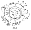
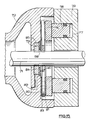
- the self-energising disc brake illustrated in Figures 1 and 2 of the accompanying drawings is of the conventional spreading type in which two friction discs 1, 2 each provided on opposite sides with linings of friction material and splined on a shaft 3 are adapted to be brought into engagement with spaced opposed braking surfaces 6, 7 in a housing 4 by an actuating mechanism 5.
- the actuating mechanism 5 comprises a pair of pressure plates 8, 9 located between the discs 1, 2 and centred by angularly spaced pilot lugs (not shown) projecting inwardly from the housing 4, and balls or rollers 10 located in co-operating oppositely inclined recesses in adjacent faces of the pressure plates 8, 9.
- the application of the brake is initiated by moving the pressure plates 8, 9 angularly in opposite directions. This, in turn, urges the friction discs 1, 2 into engagement with braking surfaces 6, 7 in the housing 4.
- the pressure plates 8, 9 are then carried round with the discs 1, 2 until one is arrested by the engagement of a lug on a respective plate 8, 9 with a drag-taking abutment in the housing 4, whereafter continued angular movement of the other plate provides a servo action.
- the application of the brake can be initiated for normal service braking by means of an hydraulic actuator acting between a pair of radial lugs 11, 12 on the pressure plates, and for parking or emergency braking by moving the coupled inner ends of a pair of toggle links 13, 14 in a radially outwards direction, the toggle links at their inner ends in turn being coupled to the pressure plates 8, 9.
- a rotatable vane pump 20 is installed in the actuating mechanism 5.
- the pump comprises an annular rotor 21 which is keyed to the shaft, and is rotatable in an eccentric bore 22 in the pressure plate 8 which defines the pump chamber and is arranged with its portion of greatest radial dimension uppermost.
- the rotor 21 is provided with three angularly spaced radial vanes 23 which are radially movable in slots in the rotor 21, and are spring loaded into engagement with the wall of the bore 22.
- the bore 22 is machined into the pressure plate 8 from its inner face so that a wall 24 defines the outer end of the pump chamber, and the opposite, inner end, is defined by a cover plate 25.
- the lower part of the housing 4 defines a sump 30 for liquid.
- An inlet passage 26 in the plate 8 has an inlet port 27 located at the lowest point of the pressure plate 8, and the inlet port is immersed in the sump.
- the passage 26 extends circumferentially to a position above a horizontal plane passing through the axis of the shaft 3, and a circumferentially extending slot 28 is provided in the cover plate 25.
- the rotor 21 rotates with the shaft 3 and draws liquid from the sump 30.
- the liquid is pumped from the inlet port 27 for discharge to a space above the shaft 3 for cooling the braking surfaces, and liquid is also discharged through the slot 28 so that a flow of liquid takes place in both directions from the actuator mechanism 5.
- vanes 23 are tangentially arranged within the rotor 21. This enables us to provide a relatively smaller rotor 21 and hence increases the swept volume and the quantity of liquid displaced for a given number of rotations.
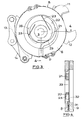
- valves 31 and 32 are mounted on opposite sides of the cover plate 25, suitably by welding.
- Each valve comprises a metal strip.
- the valve 31 controls flow through the inlet passage from the sump 30, and the valve 32 controls the flow from the passage 26 through a port 33 in the cover plate 25.
- valve 32 When the shaft is rotating in the opposite reverse direction, the valve 32 is open, and the pressure in the passage 26 above the reed valve 31 is above ambient so that the reed valve 31 closes to prevent liquid being pumped back to the sump. This might otherwise cause aeration of the liquid which would reduce its effectiveness as a coolant.
- the pump rotor 21 is provided with a pair of diametrically arranged vanes 23, and the inlet port 27 communicates with the sump 30 through a dip tube 45.
- each friction disc 1, 2 is adapted to form a pump impellor.
- the disc 1, 2 is provided on one side with an annular dish shaped member 50 comprising a cylindrical body part 51 which is secured to the disc 1, 2 surrounding its central opening, and a radial flange 52 which extends outwardly from the outer end of the body part 51.
- An annular chamber 53 which opens outwardly, is defined between the flange 52 and the braking member 1, 2.
- a plurality of angularly spaced vanes or scoops 54 of arcuate outline extend between the body part 51, the flange 52 and the braking member 1, 2 to raise liquid from the sump 30 when the disc 1, 2 is rotating in a normal forward direction.
- a plurality of openings 55 are provided in the disc adjacent to the body part 51. Each opening 55 is disposed adjacent to the inner end of the concave side of each vane 54.
- the opposite side of the disc 1, 2 carries an annular member 56 substantially of U or channel outline which is superimposed at its inner end over the member 50.
- the member 56 has a cylindrical body part 57, from the outer end of which a radial flange 58 extends in an outwards direction, and the flange 58 is cranked at intermediate point in its length to form a circumferentially extending axial extension 59 which is spaced at its free end from the friction disc 1, 2 to define an annular gap 60 for the escape of liquid.
- the liquid When the disc is rotating in a normal forward direction, the liquid is raised from the sump 30 at the level 61 by the vanes 54, and passes through the openings 55 into the interior of the member 56 which defines a reservoir 62, and from which it can escape to the braking surfaces through the gap 60.
- the vanes 54 raise the liquid from the level 61 to an effective level 63 in the reservoir 62.
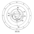
- an axially movable friction disc 70 slidably mounted on a shaft 71 to be braked and located in a housing 72 is adapted to be clamped between a braking face 73 on the housing 72 and an annular pressure plate 74.
- the pressure plate 74 is guided for axial sliding movement in the housing and is adapted to be urged into engagement with the friction disc 70 to apply the brake by the operation of an annular hydraulic piston 76 which works in an annular cylinder 77 in the adjacent end wall 78 of the housing 72.
- a pump mechanism 79 is incorporated in the end wall 78 of the housing to pump cooling liquid to the friction linings 80, 81 carried by opposite faces of a core plate 83, and which together with the linings, constitutes the friction disc 70.
- the pump mechanism 79 comprises an annular rotor 84 which is keyed to the shaft 71, and is rotatable in an eccentric bore 85 in the end wall 78 which defines a pump chamber and which is arranged with its portion of greatest radial dimension uppermost.
- the rotor is provided with three angularly spaced radial vanes 86, which are radially movable in slots 87 in the rotor, and are spring-loaded into engagement with the wall of the bore 85.
- the bore 85 is machined into the inner end face of the end wall 78, with the outer end closed by a cover plate 88 defining the outer end of the pump chamber.
- the rotor 84 rotates with the shaft 71 and draws liquid from an inlet passage 89 for discharge to a space above the inner peripheral edge of the linings 80, 81 through a circumferentially extending outlet port 90 in the cover plate 88.
- the pump mechanism 79 is installed in the wall of the housing 72 which incorporates the braking face 73, in a position disposed radially inwardly of the inner radial edges of the friction lining 80 and 81.
- the pressure plate 74 is increased inwardly in a radial direction and the pump mechanism 79 is incorporated in the pressure plate 74 itself.
- the brake illustrated in Figure 17 is similar to Figure 16. In this construction however the outlet 90 from the pump mechanism 79 is positioned radially outwards and within the projected area of the friction linings 80, 81. This provides a direct feed of cooling liquid to the linings.
- the brake illustrated in Figure 18 is similar to Figure 16.
- the housing 72 incorporates an additional outwardly directed outlet passage 91 through which liquid is fed directly to the linings by the pump in a manner similar to Figure 17.
- annular piston 76 may be replaced by angularly spaced pistons working in complementary bores.
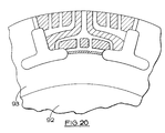
- the pump mechanism 79 comprises a turbo-disc assembly of annular outline which is separate from and outside the brake stack of which a single braking member is shown at 80, 81, 83.
- the disc assembly is illustrated in detail in Figure 20 and comprises a metal core 92 provided on opposite faces with linings of friction material.
- the disc assembly is slotted and grooved to raise liquid and discharge it to the braking members.
- the disc assembly 79 need not be described further herein since it forms the subject of our co-pending Patent Application 8 722 295.
- the disc assembly 79 is driven by the shaft or axle 71 to which it is slidably keyed.
- the disc assembly is of greater maximum diameter than the braking member, and therefore extends beyond the braking path. This allows greater peripheral speed in comparison with that of the braking member, larger annular volume, and much lower oil feed level, that is to say better use can therefore be made for cooling purposes of the relatively lower level of oil in the axle housing.
- the outer-disc assembly is urged by a Belleville or other spring washer 95 relatively towards the stack and into engagement at its peripheral edge with an annular seal 96.
- Liquid is drawn through the slots in the disc assembly and discharged to the brake through an inwardly directed liquid discharge passage 97 between the disc assembly and an adjacent face of the housing 72.
- the turbo-disc assembly 79 may be installed as shown in Figure 21 at the entrance to an axle differential 100 to pump liquid to each of two liquid cooled brakes 101, 102, each adapted to brake one respective axle or half shaft 103, 104, each driven from the differential.
- a turbo-disc assembly 79 is associated with each brake 101, 102.
Landscapes
- Engineering & Computer Science (AREA)
- General Engineering & Computer Science (AREA)
- Mechanical Engineering (AREA)
- Braking Arrangements (AREA)
Claims (14)
- Fahrzeugscheibenbremse der flüssigkeits-gekühlten Bauart, bei welcher zumindest ein drehbares Reibbremselement (1,2) verschiebbar auf eine zu bremsende Welle (3) verkeilt ist und in einem Gehäuse (4) drehbar ist, welches eine Kühlflüssigkeit zur Kühlung des Bremselements (1,2) enthält, und bei welcher Betätigungsmittel (5) vorgesehen sind, um das Bremselement (1,2) in Eingriff mit einer relativ stationären Bremsfläche (6,7) zur Betätigung der Bremse zu bringen, wobei die Bremse einen Sammelbehälter (30) für die Flüssigkeit und einen Mechanismus (20) zum Pumpen der Flüssigkeit von einem Sammelbehälter (30) zu dem Bremselement (1,2) umfaßt, um die Bremsflächen zu kühlen, wobei der Pumpmechanismus (20) einen Einlaß- oder Aufnahmepunkt (27) unter dem Niveau der Flüssigkeit hat, sowie einen Auslaß- oder Abgabepunkt, welcher innerhalb des vorspringenden Bereichs des Bremselements (1,2) angeordnet ist, dadurch gekennzeichnet, daß ein Bereich an der Basis des Gehäuses (4) den Sammelbehälter (30) definiert und daß ein drehbares Pumpenelement (21) von der Welle (3) zur Übertragung der Flüssigkeit von dem Einlaß- oder Aufnahmepunkt (27) zu dem Auslaß- oder Abgabepunkt angetrieben wird.
- Fahrzeugscheibenbremse nach Anspruch 1, dadurch gekennzeichnet, daß das Pumpenelement selbst ein Bremselement (1,2) umfaßt.
- Fahrzeugscheibenbremse nach Anspruch 2, dadurch gekennzeichnet, daß das Bremselement (1,2) mit Mitteln (50) versehen ist, welche an zumindest einer Seite des Elements eine ringförmige Kammer definieren, welche sich in einer radial nach außen gerichteten Richtung öffnet, sowie mehrere winkelmäßig beabstandete Flügel (54), welche sich zwischen axial beabstandeten Endwandungen der Kammer erstrecken und als Schaufeln zum Anheben der Flüssigkeit von dem Sammelbehälter zu dem Abgabepunkt wirken.
- Fahrzeugscheibenbremse nach Anspruch 3, dadurch gekennzeichnet, daß die ringförmige Kammer (50) nur an einer Seite des Bremselements vorgesehen ist, und daß eine Öffnung (55), welche in dem Element an dem inneren Ende jedes Flügels (54) angeordnet ist, als Überleitungskanal für Flüssigkeit zu der gegenüberliegenden Seite des Elements wirkt, von welcher die Flüssigkeit wegen der Zentrifugalkraft über diese Seite des Bremselements fließen kann.
- Fahrzeugscheibenbremse nach Anspruch 4, dadurch gekennzeichnet, daß die Öffnungen (55) in Umfangsrichtung länglich sind und in eine ringförmige Verteilungskammer (56) an der gegenüberliegenden Seite des Bremselements führen, wobei die Verteilungskammer an ihrer radial äußersten Kante mit einer sich in Umfangsrichtung erstreckenden Mündung (60) mit reduzierter axialer Dicke versehen ist, welche benachbart zu der gegenüberliegenden Seite angeordnet ist.
- Fahrzeugscheibenbremse nach Anspruch 1, dadurch gekennzeichnet, daß das Pumpenelement einen separaten Rotor (21) zusätzlich zu einem oder mehreren Bremselementen (1,2) umfaßt.
- Fahrzeugscheibenbremse nach Anspruch 6, dadurch gekennzeichnet, daß das Pumpenelement (21) benachbart zu den Reibbremselementen (1,2) inkorporiert ist.
- Fahrzeugscheibenbremse nach Anspruch 6, dadurch gekennzeichnet, daß das Pumpenelement (79) von den Bremselementen (1,2) separiert und außerhalb der Bremse angeordnet ist.
- Fahrzeugscheibenbremse nach Anspruch 7, bei welcher die Betätigungsmittel ein Paar von ringförmigen Druckplatten (8,9) umfassen, welche zwischen einem Paar von axial beabstandeten Reibbremselementen (1,2) angeordnet sind und durch stationäre Führungsansätze an dem Gehäuse zentriert sind, und wobei Kugeln oder Walzen (10) in zusammenwirkenden, entgegengesetzt geneigten Ausnehmungen in den benachbarten Flächen der Druckplatten so angeordnet sind, daß bei Beginn der Betätigung der Bremse durch schräge Bewegung der Druckplatten in entgegengesetzte Richtungen die Druckplatten sich daraufhin auseinanderbewegen, um die Reibelemente in Eingriff mit relativ stationären Bremsflächen wegen der Bestrebung der Kugeln oder Walzen, Rampen hinauf zu rollen, welche durch die Kante der Ausnehmungen definiert sind, zu drängen, wobei die Druckplatten dann mit den Bremselementen herumgetragen werden, bis eine durch den Eingriff eines Ansatzes an der Platte mit einem einen Widerstand aufnehmenden Sperr-Widerlager in dem Gehäuse gesperrt ist, und die fortdauernde Winkelbewegung der anderen Druckplatte eine Unterstützungswirkung hervorruft, dadurch gekennzeichnet, daß der Rotor (21) auf die Welle (3) aufgekeilt ist und mit einer inneren Ausnehmung (22) zumindest einer der Druckplatten (8,9) zusammenwirkt.
- Fahrzeugscheibenbremse nach Anspruch 9, dadurch gekennzeichnet, daß die innere Ausnehmung (22) exzentrisch ist und der Rotor (21) mit zumindest zwei Flügeln (23) versehen ist, welche mit der Wandung der Ausnehmung zusammenwirken, um Flüssigkeit von dem Einlaß zu dem Auslaß zu leiten, wobei der Einlaß und der Auslaß durch Öffnungen (26,28) in der Wandung der Druckplatten (8,9) definiert sind.
- Fahrzeugscheibenbremse nach Anspruch 10, dadurch gekennzeichnet, daß zwei diametral gegenüberliegende Flügel (23) vorgesehen sind.
- Fahrzeugscheibenbremse nach Anspruch 10, dadurch gekennzeichnet, daß die Flügel winkelmäßig gleich beabstandet sind.
- Fahrzeugscheibenbremse nach einem der Ansprüche 9 bis 12, dadurch gekennzeichnet, daß der Rotor (21) in der Ausnehmung (22) nur in einer Druckplatte (8) drehbar ist, wobei die innere Ausnehmung (22) eine Bohrung einer gegengebohrten Ausnehmung umfaßt, und wobei eine Pumpraum in der inneren Ausnehmung zwischen der Basis (24) der Ausnehmung und einer Deckplatte (25), welche an dem gegenüberliegenden inneren Ende der Ausnehmung befestigt ist, definiert ist.
- Fahrzeugscheibenbremse nach Anspruch 13, dadurch gekennzeichnet, daß zwei entgegengesetzt angeordnete und wirkende Blattventile (31,32) an gegenüberliegenden Seiten der Deckplatte (25) gelagert sind.
Applications Claiming Priority (4)
| Application Number | Priority Date | Filing Date | Title |
|---|---|---|---|
| GB878717876A GB8717876D0 (en) | 1987-07-28 | 1987-07-28 | Vehicle disc brakes |
| GB8717876 | 1987-07-28 | ||
| GB8722294 | 1987-09-21 | ||
| GB878722294A GB8722294D0 (en) | 1987-07-28 | 1987-09-21 | Vehicle disc brakes |
Publications (2)
| Publication Number | Publication Date |
|---|---|
| EP0307080A1 EP0307080A1 (de) | 1989-03-15 |
| EP0307080B1 true EP0307080B1 (de) | 1992-06-03 |
Family
ID=26292545
Family Applications (1)
| Application Number | Title | Priority Date | Filing Date |
|---|---|---|---|
| EP88306734A Expired - Lifetime EP0307080B1 (de) | 1987-07-28 | 1988-07-22 | Fahrzeugscheibenbremse mit Flüssigkeitskühlung |
Country Status (3)
| Country | Link |
|---|---|
| US (1) | US4865168A (de) |
| EP (1) | EP0307080B1 (de) |
| DE (1) | DE3871669T2 (de) |
Families Citing this family (7)
| Publication number | Priority date | Publication date | Assignee | Title |
|---|---|---|---|---|
| US5394963A (en) * | 1993-06-18 | 1995-03-07 | The Budd Company | Composite cast brake caliper |
| DE19537475A1 (de) * | 1995-10-07 | 1997-04-10 | Schuler Pressen Gmbh & Co | Nutenstanzmaschine |
| US6491139B1 (en) | 2000-11-15 | 2002-12-10 | Lauro Budica | Fluid-cooled brake system |
| GB0914235D0 (en) * | 2009-08-14 | 2009-09-30 | Valtra Oy Ab | Oil cooled brakes |
| CN102338180A (zh) * | 2011-09-22 | 2012-02-01 | 芜湖恒坤汽车部件有限公司 | 制动轮缸的活塞行程调整装置 |
| CN102338173A (zh) * | 2011-09-22 | 2012-02-01 | 芜湖恒坤汽车部件有限公司 | 制动轮缸的活塞行程调整和保护装置 |
| CN102338178A (zh) * | 2011-09-22 | 2012-02-01 | 芜湖恒坤汽车部件有限公司 | 制动轮缸的排油装置 |
Citations (1)
| Publication number | Priority date | Publication date | Assignee | Title |
|---|---|---|---|---|
| EP0143898A1 (de) * | 1983-09-05 | 1985-06-12 | ZF FRIEDRICHSHAFEN Aktiengesellschaft | Reibungsbremse bzw. -kupplung mit einer Zwangskühlung |
Family Cites Families (7)
| Publication number | Priority date | Publication date | Assignee | Title |
|---|---|---|---|---|
| US3071211A (en) * | 1960-04-06 | 1963-01-01 | Gen Motors Corp | Brake cooling fluid systems |
| US3061048A (en) * | 1960-06-27 | 1962-10-30 | Gen Motors Corp | Brake cooling fluid pump |
| CH534318A (de) * | 1971-06-07 | 1973-02-28 | Saurer Ag Adolph | Vorrichtung zum kraftschlüssigen Verbinden zweier Bauteile |
| GB1445105A (en) * | 1972-10-12 | 1976-08-04 | Girling Ltd | Multi-plate disc brakers for vehicles |
| GB1440120A (en) * | 1973-09-29 | 1976-06-23 | Ferodo Ltd | Hydraulically operated friction brakes |
| US4207969A (en) * | 1974-01-14 | 1980-06-17 | Robert Howell Industries | Wet disc friction device |
| CA1189001A (en) * | 1981-10-02 | 1985-06-18 | Meritor Heavy Vehicle Technology, Llc | Fluid cooled friction brake |
-
1988
- 1988-07-22 DE DE3871669T patent/DE3871669T2/de not_active Expired - Fee Related
- 1988-07-22 EP EP88306734A patent/EP0307080B1/de not_active Expired - Lifetime
- 1988-07-28 US US07/225,308 patent/US4865168A/en not_active Expired - Fee Related
Patent Citations (1)
| Publication number | Priority date | Publication date | Assignee | Title |
|---|---|---|---|---|
| EP0143898A1 (de) * | 1983-09-05 | 1985-06-12 | ZF FRIEDRICHSHAFEN Aktiengesellschaft | Reibungsbremse bzw. -kupplung mit einer Zwangskühlung |
Also Published As
| Publication number | Publication date |
|---|---|
| US4865168A (en) | 1989-09-12 |
| DE3871669T2 (de) | 1995-03-23 |
| DE3871669D1 (de) | 1992-07-09 |
| EP0307080A1 (de) | 1989-03-15 |
Similar Documents
| Publication | Publication Date | Title |
|---|---|---|
| US4624353A (en) | Friction device | |
| US5012901A (en) | Self-energizing disc brakes | |
| US4667527A (en) | Spring-loaded brake with pressure-medium-operable lifting set | |
| US4913267A (en) | Vehicle disc brakes of the liquid cooled type | |
| CA1093981A (en) | Wet brake or clutch | |
| EP0136434B1 (de) | Scheibenbremse | |
| US5205382A (en) | Aircraft brake | |
| US3249061A (en) | Pump or motor device | |
| US4653614A (en) | Self-energizing disc brakes | |
| US5788024A (en) | Actuator for a vehicle brake, especially a disc brake | |
| US3059730A (en) | Disc brake | |
| US4458792A (en) | Automotive retarder | |
| US5291973A (en) | Disk brake for a wheel | |
| GB2296540A (en) | Wet clutch assembly | |
| US2290542A (en) | Clutch | |
| EP0307080B1 (de) | Fahrzeugscheibenbremse mit Flüssigkeitskühlung | |
| EP1058024A2 (de) | Mehrstufige nasslaufende Scheibenbremse | |
| EP0307079B1 (de) | Fahrzeugscheibenbremse mit Flüssigkeitskühlung | |
| JPS58118423A (ja) | 駆動アクスル組立体 | |
| US4346796A (en) | Drive mechanism with clutch and brake assemblies | |
| US4470485A (en) | Disc brake assembly | |
| US3303911A (en) | Fluid cooled brake mechanism | |
| US3580369A (en) | Liquid-cooled disc brake assembly | |
| EP0480358A1 (de) | Flugzeugbremse | |
| US4646889A (en) | Compressor drive with oil distribution sleeve |
Legal Events
| Date | Code | Title | Description |
|---|---|---|---|
| PUAI | Public reference made under article 153(3) epc to a published international application that has entered the european phase |
Free format text: ORIGINAL CODE: 0009012 |
|
| AK | Designated contracting states |
Kind code of ref document: A1 Designated state(s): DE ES FR GB IT |
|
| 17P | Request for examination filed |
Effective date: 19890818 |
|
| 17Q | First examination report despatched |
Effective date: 19901010 |
|
| GRAA | (expected) grant |
Free format text: ORIGINAL CODE: 0009210 |
|
| AK | Designated contracting states |
Kind code of ref document: B1 Designated state(s): DE ES FR GB IT |
|
| PG25 | Lapsed in a contracting state [announced via postgrant information from national office to epo] |
Ref country code: ES Free format text: THE PATENT HAS BEEN ANNULLED BY A DECISION OF A NATIONAL AUTHORITY Effective date: 19920603 |
|
| ITF | It: translation for a ep patent filed | ||
| REF | Corresponds to: |
Ref document number: 3871669 Country of ref document: DE Date of ref document: 19920709 |
|
| ET | Fr: translation filed | ||
| PLBE | No opposition filed within time limit |
Free format text: ORIGINAL CODE: 0009261 |
|
| STAA | Information on the status of an ep patent application or granted ep patent |
Free format text: STATUS: NO OPPOSITION FILED WITHIN TIME LIMIT |
|
| 26N | No opposition filed | ||
| PGFP | Annual fee paid to national office [announced via postgrant information from national office to epo] |
Ref country code: GB Payment date: 19930609 Year of fee payment: 6 |
|
| PGFP | Annual fee paid to national office [announced via postgrant information from national office to epo] |
Ref country code: FR Payment date: 19930611 Year of fee payment: 6 |
|
| PGFP | Annual fee paid to national office [announced via postgrant information from national office to epo] |
Ref country code: DE Payment date: 19930908 Year of fee payment: 6 |
|
| PG25 | Lapsed in a contracting state [announced via postgrant information from national office to epo] |
Ref country code: GB Effective date: 19940722 |
|
| GBPC | Gb: european patent ceased through non-payment of renewal fee |
Effective date: 19940722 |
|
| PG25 | Lapsed in a contracting state [announced via postgrant information from national office to epo] |
Ref country code: FR Effective date: 19950331 |
|
| PG25 | Lapsed in a contracting state [announced via postgrant information from national office to epo] |
Ref country code: DE Effective date: 19950401 |
|
| REG | Reference to a national code |
Ref country code: FR Ref legal event code: ST |
|
| PG25 | Lapsed in a contracting state [announced via postgrant information from national office to epo] |
Ref country code: IT Free format text: LAPSE BECAUSE OF NON-PAYMENT OF DUE FEES;WARNING: LAPSES OF ITALIAN PATENTS WITH EFFECTIVE DATE BEFORE 2007 MAY HAVE OCCURRED AT ANY TIME BEFORE 2007. THE CORRECT EFFECTIVE DATE MAY BE DIFFERENT FROM THE ONE RECORDED. Effective date: 20050722 |