EP0307169A1 - Fermeture inviolable - Google Patents
Fermeture inviolable Download PDFInfo
- Publication number
- EP0307169A1 EP0307169A1 EP88308236A EP88308236A EP0307169A1 EP 0307169 A1 EP0307169 A1 EP 0307169A1 EP 88308236 A EP88308236 A EP 88308236A EP 88308236 A EP88308236 A EP 88308236A EP 0307169 A1 EP0307169 A1 EP 0307169A1
- Authority
- EP
- European Patent Office
- Prior art keywords
- closure
- band
- skirt
- tabs
- finish
- Prior art date
- Legal status (The legal status is an assumption and is not a legal conclusion. Google has not performed a legal analysis and makes no representation as to the accuracy of the status listed.)
- Withdrawn
Links
- 238000010276 construction Methods 0.000 claims abstract description 6
- 230000001419 dependent effect Effects 0.000 claims abstract description 5
- 238000007789 sealing Methods 0.000 claims abstract description 4
- 238000009434 installation Methods 0.000 claims description 18
- 230000002028 premature Effects 0.000 claims description 4
- 241000711981 Sais Species 0.000 claims 1
- 239000011521 glass Substances 0.000 description 4
- 239000000463 material Substances 0.000 description 2
- 238000000465 moulding Methods 0.000 description 2
- 238000000926 separation method Methods 0.000 description 2
- 239000004743 Polypropylene Substances 0.000 description 1
- 230000006870 function Effects 0.000 description 1
- 230000014759 maintenance of location Effects 0.000 description 1
- 238000004519 manufacturing process Methods 0.000 description 1
- 238000000034 method Methods 0.000 description 1
- 239000004033 plastic Substances 0.000 description 1
- -1 polypropylene Polymers 0.000 description 1
- 229920001155 polypropylene Polymers 0.000 description 1
- 238000005096 rolling process Methods 0.000 description 1
- 239000007787 solid Substances 0.000 description 1
- 229920001169 thermoplastic Polymers 0.000 description 1
- 239000004416 thermosoftening plastic Substances 0.000 description 1
Images
Classifications
-
- B—PERFORMING OPERATIONS; TRANSPORTING
- B65—CONVEYING; PACKING; STORING; HANDLING THIN OR FILAMENTARY MATERIAL
- B65D—CONTAINERS FOR STORAGE OR TRANSPORT OF ARTICLES OR MATERIALS, e.g. BAGS, BARRELS, BOTTLES, BOXES, CANS, CARTONS, CRATES, DRUMS, JARS, TANKS, HOPPERS, FORWARDING CONTAINERS; ACCESSORIES, CLOSURES, OR FITTINGS THEREFOR; PACKAGING ELEMENTS; PACKAGES
- B65D41/00—Caps, e.g. crown caps or crown seals, i.e. members having parts arranged for engagement with the external periphery of a neck or wall defining a pouring opening or discharge aperture; Protective cap-like covers for closure members, e.g. decorative covers of metal foil or paper
- B65D41/32—Caps or cap-like covers with lines of weakness, tearing-strips, tags, or like opening or removal devices, e.g. to facilitate formation of pouring openings
- B65D41/34—Threaded or like caps or cap-like covers provided with tamper elements formed in, or attached to, the closure skirt
- B65D41/3423—Threaded or like caps or cap-like covers provided with tamper elements formed in, or attached to, the closure skirt with flexible tabs, or elements rotated from a non-engaging to an engaging position, formed on the tamper element or in the closure skirt
- B65D41/3428—Threaded or like caps or cap-like covers provided with tamper elements formed in, or attached to, the closure skirt with flexible tabs, or elements rotated from a non-engaging to an engaging position, formed on the tamper element or in the closure skirt the tamper element being integrally connected to the closure by means of bridges
- B65D41/3433—Threaded or like caps or cap-like covers provided with tamper elements formed in, or attached to, the closure skirt with flexible tabs, or elements rotated from a non-engaging to an engaging position, formed on the tamper element or in the closure skirt the tamper element being integrally connected to the closure by means of bridges with drive means between closure and tamper element
Definitions
- This invention relates to closures for containers and, more specifically, to a closure having a tamper-evident assembly including abutment tabs on a band connected to the cap by breakable bridges.
- closures which provide an indication that a container has been opened.
- Such closures typically have a frangible band assembly which breaks away from the cap (to which it is connected by a number of thin frangible bridges) and remains on the container finish upon the first opening of the container.
- Certain closures include a large number of tabs extending upwardly and inwardly from the base of the band and abut a large annular shoulder projection or breaker ledge on the container finish beneath the screw thread to cause separation of the tamper-evident band assembly upon the first opening of the container.
- Such closures work satisfactory with relatively narrow-mouth closures.
- Closures have been proposed which include annular inwardly folded ring which extends upwardly and inwardly from the tamper-evident band for abutting the finish breaker ledge.
- the requirement to stretch a full ring results in the need to apply excessive force to install the closure.
- the glass tolerance may be, e.g., plus 0.030 and minus 0.035 cms (plus 0.012 and minus 0.013 inch).
- the closure of the present invention has relatively low installation force and reduces the possibility of tab inversion and interlocking even when manufactured in wide diameter sizes. Furthermore, the frangible bridges are protected from premature rupture during installation of the cap. Additionally, the closure of the present invention is reliable in use with glass containers of large sizes having considerable variations in diameter and is easy and economical to manufacture.
- a closure embodying various aspects of the present invention is of one-piece molded construction and includes a cap including a top wall extending across the opening of the finish and an annular skirt dependent from the top wall with the top wall and skirt being substantially coaxial and with the skirt having an internal thread.
- the closure further includes a tamper-indicating assembly made up of a band positioned below and spaced from the skirt with a plurality of spaced frangible bridges detachably connecting the upper end of the band to the lower end of the skirt.
- a segmented ring is connected to the bottom of the band and extends upwardly and inwardly therefrom with the ring being made up of a number of segments, adjacent ones of which are separated by a slot providing more flexibility than a solid, annular flange in passing over maximum tolerance diameters on containers.
- the assembly further includes a plurality of resilient tabs connected to each segment and extending upwardly and inwardly therefrom with distal tab ends engaging the breaker ledge abutment surface upon attempted removal of the closure after its installation on the finish.
- the tabs are sufficiently resiliently outwardly deflectable by the breaker ledge cam surface during installation of the closure on the finish so that upon removal of an installed closure, and, on the other hand, the tabs are sufficiently stiff that the free ends of the tabs bearing on the ledge will cause the bridges to break resulting in an indication of tampering.
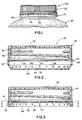
- a tamper-evident closure embodying various aspects of the present invention is generally indicated by reference numeral 20.
- the closure 20 is preferably of one-piece molded thermoplastic construction with a preferred material being polypropylene, and includes a cap 22 and a tamper-evident assembly 24 joined to the cap by a number of regularly spaced frangible bridges 26.
- Closure 20 is useful for sealing an open-topped contained 28, portions of which are shown in FIGS. 1 and 4, including a neck or finish 30 having an external screw thread 32 and an annular projecting shoulder or breaker ledge 34 disposed beneath the level of the thread 32.
- the ledge 34 is provided with an upper cam surface 36 facing the thread and a lower abutment surface 38 remote from the thread.
- the tamper-evident assembly is, in essence, a one-way device which cooperates with the cam surface to permit relatively low force movement of the assembly beneath the level of the ledge during installation of the closure, but which cooperates with ledge abutment surface to break the bridges when the cap is first removed from the container.
- the cap 22 includes an annular top wall 40 for extending across the opening of the finish 30.
- An annular sidewall or skirt 42 is dependent from the top wall 40 and is joined thereto about the periphery of the top wall so that the top wall and the skirt are substantially coaxial.
- the skirt 42 has an internal screw thread 44 configured to cooperate with the thread of the finish to enable the cap 22 to be installed on the removed from the container 28 by screwing and unscrewing, respectively.
- the skirt 42 is preferably provided with an internal retention rib adjacent the top of the internal screw thread 44 for retaining a disc of resiliently compressible material which is compressed between the top wall 40 and the open-end of the finish to seal the open end.
- the exterior surface of the skirt preferably has a large number of regularly spaced axially extending ribs to enhance the user's grip on the cap.
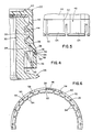
- the tamper-indicating assembly 24 is best shown in its ready-for-application condition in FIGS. 3 and 6 and comprises a band 46 of relatively thick cross section connected to the outwardly flaring bottom of the skirt by the thin bridges 26.
- the tamper-evident band has increased rigidity over the tabs on the closure of U.S. Patent No. 4,511,054 because of a segmented ring 48 and has greater flexibility for large diameter tolerances than the full annular ring of U.S. Patent No. 4,653,657 because of tabs 54 projecting from the ring segments to engage the breaker ledge.
- the segmented ring 48 is connected to the base of the band and extends upwardly and inwardly therefrom.
- the ring 48 is made up by three to five segments 50, four being preferable, with adjacent segments separated by a slot 52 extending substantially to the band.
- a plurality of resilient tabs 54 is connected to the distal end of each segment for engaging the abutment surface 38 of the breaker ledge 34. There are preferably six to ten tabs carried by each segment with eight per segment being most preferable.
- the ring and tabs extend downwardly because this configuration permits simplification in the molding process and equipment.
- the segment ring and the tabs are reoriented by rolling or any other suitable means, as well known by those of skill in the art, to extend upwardly. Heat may be applied to destroy the plastic memory at the hinge area, if desired.
- the components will remain in ready-for-installation position depicted in FIGS. 3 and 6.
- the tabs increase in thickness with distance from their connected ends and, as shown in FIG. 5, have a slight decrease in width from their connected ends.
- the segments 50 also increase in thickness with distance from the band with the segments and tabs having substnatially equal thickness at their juncture.
- the increase in thickness provides some increase in stiffness but also aids in preventing the tabs from being bent over the breaker ledge without breaking the bridges. This is termed “tiring off” in the manner that a tire is canted and inclined and peeled about the tire rim.
- the internal diameter at the base of the skirt and the internal diameter of the band 46 are substantially equal.
- the tabs 54 have their greatest thickness at their free ends to take up tolerances and prevent tiring off of the tamper-evident band with the cap during cap removal.
- installation of the closure 20 of the finish 30 causes substantially full outward deflection of the tabs 54 but does not result in substantial deformation as would break the bridges 26.
- Adjacent bridges 26 are spaced by abutment blocks 58 which function to limit movement of the band 46 toward the bottom 56 of the skirt during installation of the closure to protect against premature breakage of the bridges. More specifically, the blocks 58, which may be of rectangular cross section, extend from the top surface 60 of the band 46 about halfway toward the bottom surface 62 of the skirt.
- the relatively thin bridges as shown in FIG. 4, are positioned at the inside of the band whereas the relatively thick blocks 58 have the same thickness as the band and skirt bottom and are alinged therewith. Accordingly, the blocks have much greater column strength than the bridges.
- the thin bridges 26 may buckle and permit the bottom surface of the skirt to abut the top surface of the blocks 58 and prevent further buckling of the bridges to the extent that the bridges are damaged or broken.
- each of the segments is folded upwardly and inwardly when put into a feeding hopper for an automatic capping machine.
- the ring segment Because the long arcuate ring segment is much stiffer than would be a narrow long tab (if the ring segment were not used in patent 4,511,054) the ring segment will not be inadvertently inverted as it would, with its relatively high stiffness, have to be pulled over center and then to a reversely bowed configuration. Even if one of the tabs were acted upon by a force trying to invert it or its attached ring segment, the ring is sufficiently stiff that it should not invert. Still the closure provides acceptably low installation force because the relatively flexible tabs can be easily deflected by the downwardly sloping cam surface 36 of the breaker ledge 34. The segmented ring can also be deflected without excessive force because no full hoop kind of stretching is required (as would be required for installation of a full ring).
- Operation of the closure 20 of the subject invention is as follows: Upon placing the closure over the open end of the container finish 30 and engaging the cooperating screw threads 32 and 44, screwing of the closure results in the segmented ring 48 engaging the cam surface 36 of the breaker ledge 34. Continued screwing of the closure onto the container causes the cam surface to deflect the ring segments 50 and then deflect the tabs 54 carried by the segments. As shown in phantom in FIG. 4, when the tabs are fully deflected they are disposed adjacent or against the inside surfaces of the band 46, the bridges 26 and the lower portion of the skirt 42. When the free ends of the tabs 54 pass the greatest diameter portion of the breaker ledge, the tabs, due to their resiliency, will return toward their undeflected position and engage the finish exterior surface beneath the level of the breaker ledge 34.
- the bridges may undergo some slight buckling or bowing as the cap 22 moves toward tamper-evident assembly 24 due to the drag of the segments 50 and/or tabs 54 on the breaker ledge.
- This bowing is limited by the presence of the blocks 58 which engage the bottom surface 62 of the skirt 42 to limit movement of the band toward the skirt thereby protecting the bridges from breakage or other premature damage during closure installation.
- the free ends of the tabs are brought into engagement with the abutment surface 38 of the breaker ledge 34. Continued unscrewing causes the tabs to more forcefully bear upon this surface.
- the resistive strength of the tabs 54 is greater than the rupture strength of the bridges 26 so that upon continued application of unscrewing forces the bridges rupture allowing the cap to be removed, with the tamper-evident assembly 24 remaining captured on the finish beneath the level of the breaker ledge thereby providing positive indication that the container has been opened.
Landscapes
- Engineering & Computer Science (AREA)
- Mechanical Engineering (AREA)
- Closures For Containers (AREA)
Applications Claiming Priority (2)
| Application Number | Priority Date | Filing Date | Title |
|---|---|---|---|
| US07/095,547 US4807771A (en) | 1987-09-11 | 1987-09-11 | Tamper-evident closure |
| US95547 | 1987-09-11 |
Publications (1)
| Publication Number | Publication Date |
|---|---|
| EP0307169A1 true EP0307169A1 (fr) | 1989-03-15 |
Family
ID=22252512
Family Applications (1)
| Application Number | Title | Priority Date | Filing Date |
|---|---|---|---|
| EP88308236A Withdrawn EP0307169A1 (fr) | 1987-09-11 | 1988-09-06 | Fermeture inviolable |
Country Status (3)
| Country | Link |
|---|---|
| US (1) | US4807771A (fr) |
| EP (1) | EP0307169A1 (fr) |
| CA (1) | CA1316492C (fr) |
Cited By (4)
| Publication number | Priority date | Publication date | Assignee | Title |
|---|---|---|---|---|
| EP0410059A1 (fr) * | 1989-07-27 | 1991-01-30 | Owens-Illinois Closure Inc., | Emballage indicateur de violation, méthode et dispositif de fabrication de sa fermeture |
| WO1991001924A1 (fr) * | 1989-08-02 | 1991-02-21 | Cmb Foodcan Plc | Fermeture de securite |
| EP0766975A1 (fr) * | 1995-10-06 | 1997-04-09 | Arzneimittel GmbH Apotheker Vetter & Co. Ravensburg | Seringue pour application médicale |
| US10315808B2 (en) | 2015-10-28 | 2019-06-11 | Greif International Holding Bv | Container closure cap and container closure |
Families Citing this family (41)
| Publication number | Priority date | Publication date | Assignee | Title |
|---|---|---|---|---|
| US4938370B1 (en) * | 1989-04-26 | 2000-10-17 | Hc Ind | Tamper-indicating plastic closure |
| US5755347A (en) * | 1989-07-27 | 1998-05-26 | Owens-Illinois Closure Inc. | Tamper indicating package |
| US5219507A (en) * | 1989-07-27 | 1993-06-15 | Owens-Illinois Closure Inc. | Method of making a tamper indicating package |
| US5058755A (en) * | 1989-09-01 | 1991-10-22 | Anchor Hocking Packaging Company | Tamper indicating closure having retaining hoop with relief windows |
| US5080246A (en) * | 1989-09-01 | 1992-01-14 | Anchor Hocking Packaging Company | Closure having a spring open tamper evidencing band |
| US4971212A (en) * | 1989-10-06 | 1990-11-20 | Owens-Illinois Closure Inc. | Tamper indicating packages |
| US4981230A (en) * | 1990-03-15 | 1991-01-01 | Continental White Cap, Inc. | Composite cap including tamper indicating band |
| US5145078A (en) * | 1990-06-14 | 1992-09-08 | Charles Hannon | Pilfer-proof bottle cap |
| US5135123A (en) * | 1990-09-20 | 1992-08-04 | Phoenix Closures, Inc. | Tamper-evident closure with a separately formed break away band |
| IT1242923B (it) * | 1990-10-17 | 1994-05-18 | Bormioli Metalplast Spa | Capsula in plastica in due pezzi, per bottiglie |
| US5137163A (en) * | 1991-10-04 | 1992-08-11 | Phoenix Closures, Inc. | Tamper evident closure with ramped contact |
| ES1021753U (es) * | 1992-05-29 | 1993-01-16 | Novembal, S.A. | Dispositivo de obturacion a rosca perfeccionado. |
| US5271512A (en) * | 1992-11-06 | 1993-12-21 | Phoenix Closures, Inc. | Tamper-evident closure with reinforced band |
| US5443171A (en) * | 1993-03-26 | 1995-08-22 | Owens-Illinois Closure Inc. | Tamper indicating package |
| JP3256344B2 (ja) | 1993-07-21 | 2002-02-12 | 日本山村硝子株式会社 | ピルファープルーフキャップ |
| US5450972A (en) * | 1994-03-03 | 1995-09-19 | Phoenix Closures, Inc. | Tamper-evident band for closures |
| US5413235A (en) * | 1994-09-28 | 1995-05-09 | Decelles; Gilles | Tamper-evident closure |
| US5540342A (en) * | 1994-12-22 | 1996-07-30 | Rathbun Family Real Estate Group | Tamper resistant lid |
| US5813553A (en) * | 1995-06-07 | 1998-09-29 | Kerr Group, Inc. | Snap-band tamper evident |
| US5755346A (en) * | 1996-11-04 | 1998-05-26 | Phoenix Closures, Inc. | Tamper indicating closure with dual-camming projection band |
| US5950849A (en) * | 1997-05-12 | 1999-09-14 | Phoenix Closures, Inc. | Container closure with ribbed enlarged grasping region |
| US5967351A (en) * | 1997-07-10 | 1999-10-19 | Phoenix Closures, Inc. | Tamper-indicating closure with tapered connectors |
| US5853097A (en) * | 1997-07-10 | 1998-12-29 | Phoenix Closures, Inc. | Ribbed container closure |
| US6085921A (en) * | 1998-02-26 | 2000-07-11 | Crown Cork & Seal Technologies Corporation | Tamper evident band with undercut |
| US6053344A (en) * | 1998-07-02 | 2000-04-25 | Owens-Illinois Closure Inc. | Tamper-indicating closure and method of manufacture |
| US7344039B2 (en) * | 1998-08-07 | 2008-03-18 | Berry Plastics Corporation | Tamper indicating band having foldable tabs including tab extensions, tamper indicating closure including such tamper indicating band, and tamper indicating closure including such tamper indicating band and container |
| US6371317B1 (en) | 1998-08-07 | 2002-04-16 | Kerr Group, Inc. | Tamper indicating closure with foldable tab |
| US6253939B1 (en) | 1999-01-04 | 2001-07-03 | Crown Cork & Seal Technologies Corporation | Tamper-evident closure having improved drainage |
| US6405886B1 (en) * | 2001-02-08 | 2002-06-18 | Rexam Medical Packaging Inc. | Closure having a tamper indicating band |
| US7300633B2 (en) * | 2001-07-25 | 2007-11-27 | Oakville Hong Kong Company Limited | Specimen collection container |
| US7270959B2 (en) | 2001-07-25 | 2007-09-18 | Oakville Hong Kong Company Limited | Specimen collection container |
| US6877624B2 (en) * | 2002-01-02 | 2005-04-12 | Erie County Plastics | Method of injection molding closure with continuous internal rigid rib, closure made thereby having a lead-in structure and mold for forming same |
| US7560272B2 (en) | 2003-01-04 | 2009-07-14 | Inverness Medical Switzerland Gmbh | Specimen collection and assay container |
| US7517495B2 (en) * | 2003-08-25 | 2009-04-14 | Inverness Medical Switzerland Gmbh | Biological specimen collection and analysis system |
| US20080112847A1 (en) * | 2006-11-15 | 2008-05-15 | Nancy Yu Chen | Collecting and testing device and method of use |
| US8353413B2 (en) * | 2007-01-05 | 2013-01-15 | Phoenix Closures, Inc. | Tamper-evident closure and container combination |
| US10532858B2 (en) * | 2017-09-06 | 2020-01-14 | Creanova Universal Closures Ltd. | Closure for container neck finishes |
| US11059633B2 (en) | 2019-10-31 | 2021-07-13 | Cheer Pack North America | Flip-top closure for container |
| US12054318B2 (en) * | 2019-11-15 | 2024-08-06 | Novembal Usa Inc. | Stopper having a tamper-evident band |
| US12280921B2 (en) * | 2020-08-20 | 2025-04-22 | Sidel Participations Sas | Hinged closure |
| US20220097935A1 (en) * | 2020-09-28 | 2022-03-31 | Closure Systems International Inc. | Package and closure with tamper-evident band |
Citations (3)
| Publication number | Priority date | Publication date | Assignee | Title |
|---|---|---|---|---|
| EP0214711A1 (fr) * | 1985-08-29 | 1987-03-18 | Kerr Glass Manufacturing Corporation | Fermeture de protection à l'épreuve des enfants avec moyens pour indiquer l'ouverture |
| US4653657A (en) * | 1986-01-21 | 1987-03-31 | Owens-Illinois, Inc. | Tamper indicating package |
| US4657153A (en) * | 1985-11-18 | 1987-04-14 | Anchor Hocking Corporation | Tamper-evident closure |
Family Cites Families (2)
| Publication number | Priority date | Publication date | Assignee | Title |
|---|---|---|---|---|
| US4478343A (en) * | 1982-09-23 | 1984-10-23 | Ethyl Molded Products Company | Tamper-indicating closure |
| US4572388A (en) * | 1985-03-18 | 1986-02-25 | Sunbeam Plastics Corporation | Tamper indicating screw cap |
-
1987
- 1987-09-11 US US07/095,547 patent/US4807771A/en not_active Expired - Fee Related
-
1988
- 1988-09-06 EP EP88308236A patent/EP0307169A1/fr not_active Withdrawn
- 1988-09-08 CA CA000576773A patent/CA1316492C/fr not_active Expired - Lifetime
Patent Citations (3)
| Publication number | Priority date | Publication date | Assignee | Title |
|---|---|---|---|---|
| EP0214711A1 (fr) * | 1985-08-29 | 1987-03-18 | Kerr Glass Manufacturing Corporation | Fermeture de protection à l'épreuve des enfants avec moyens pour indiquer l'ouverture |
| US4657153A (en) * | 1985-11-18 | 1987-04-14 | Anchor Hocking Corporation | Tamper-evident closure |
| US4653657A (en) * | 1986-01-21 | 1987-03-31 | Owens-Illinois, Inc. | Tamper indicating package |
Cited By (4)
| Publication number | Priority date | Publication date | Assignee | Title |
|---|---|---|---|---|
| EP0410059A1 (fr) * | 1989-07-27 | 1991-01-30 | Owens-Illinois Closure Inc., | Emballage indicateur de violation, méthode et dispositif de fabrication de sa fermeture |
| WO1991001924A1 (fr) * | 1989-08-02 | 1991-02-21 | Cmb Foodcan Plc | Fermeture de securite |
| EP0766975A1 (fr) * | 1995-10-06 | 1997-04-09 | Arzneimittel GmbH Apotheker Vetter & Co. Ravensburg | Seringue pour application médicale |
| US10315808B2 (en) | 2015-10-28 | 2019-06-11 | Greif International Holding Bv | Container closure cap and container closure |
Also Published As
| Publication number | Publication date |
|---|---|
| US4807771A (en) | 1989-02-28 |
| CA1316492C (fr) | 1993-04-20 |
Similar Documents
| Publication | Publication Date | Title |
|---|---|---|
| US4807771A (en) | Tamper-evident closure | |
| US4741447A (en) | Linerless cap closure | |
| US4878589A (en) | Linerless cap closure | |
| RU2139230C1 (ru) | Крышка с присоединенной полоской индикации вскрытия | |
| US4479586A (en) | Tamper-evident container with drop down skirt | |
| EP0214711B1 (fr) | Fermeture de protection à l'épreuve des enfants avec moyens pour indiquer l'ouverture | |
| US5007545A (en) | Removal resistant member | |
| US4966292A (en) | Cap and neck finish for a wide mouth container | |
| EP0166572B1 (fr) | Fermeture inviolable munie d'une bande d'arrachage | |
| EP1256523B1 (fr) | Moule pour former des capuchons de fermeture anti-fraude | |
| US4938370A (en) | Tamper-indicating plastic closure | |
| US4470513A (en) | Tamper-indicating closure | |
| US4387818A (en) | Snap-on tamper-proof closure | |
| US4664278A (en) | Tamper indicating package | |
| US4653657A (en) | Tamper indicating package | |
| EP0616951B1 (fr) | Emballage à témoin de spoliation | |
| US4458822A (en) | Tamper-indicating closure | |
| US4529096A (en) | Pilferproof cap | |
| US5137163A (en) | Tamper evident closure with ramped contact | |
| US20050145629A1 (en) | Closure and container system and method for sealing a closure on a container | |
| JPH0353181B2 (fr) | ||
| US4732293A (en) | Tear strip closure for a container with a security ring | |
| US4667838A (en) | Tamper-evident closure with ribbed skirt | |
| GB2143512A (en) | Container closure | |
| EP0262868B1 (fr) | Bande de garantie pour une fermeture de réceptacle |
Legal Events
| Date | Code | Title | Description |
|---|---|---|---|
| PUAI | Public reference made under article 153(3) epc to a published international application that has entered the european phase |
Free format text: ORIGINAL CODE: 0009012 |
|
| AK | Designated contracting states |
Kind code of ref document: A1 Designated state(s): BE DE FR GB IT |
|
| 17P | Request for examination filed |
Effective date: 19890505 |
|
| 17Q | First examination report despatched |
Effective date: 19901031 |
|
| STAA | Information on the status of an ep patent application or granted ep patent |
Free format text: STATUS: THE APPLICATION IS DEEMED TO BE WITHDRAWN |
|
| 18D | Application deemed to be withdrawn |
Effective date: 19911015 |