EP0307432B1 - Permanentmagnetsystem zur erzeugung eines intensiven magnetfeldes - Google Patents
Permanentmagnetsystem zur erzeugung eines intensiven magnetfeldes Download PDFInfo
- Publication number
- EP0307432B1 EP0307432B1 EP88902491A EP88902491A EP0307432B1 EP 0307432 B1 EP0307432 B1 EP 0307432B1 EP 88902491 A EP88902491 A EP 88902491A EP 88902491 A EP88902491 A EP 88902491A EP 0307432 B1 EP0307432 B1 EP 0307432B1
- Authority
- EP
- European Patent Office
- Prior art keywords
- permanent magnets
- lateral
- air gap
- main
- magnets
- Prior art date
- Legal status (The legal status is an assumption and is not a legal conclusion. Google has not performed a legal analysis and makes no representation as to the accuracy of the status listed.)
- Expired - Lifetime
Links
Images

Classifications
-
- H—ELECTRICITY
- H01—ELECTRIC ELEMENTS
- H01F—MAGNETS; INDUCTANCES; TRANSFORMERS; SELECTION OF MATERIALS FOR THEIR MAGNETIC PROPERTIES
- H01F7/00—Magnets
- H01F7/02—Permanent magnets [PM]
- H01F7/0273—Magnetic circuits with PM for magnetic field generation
- H01F7/0278—Magnetic circuits with PM for magnetic field generation for generating uniform fields, focusing, deflecting electrically charged particles
- H01F7/0284—Magnetic circuits with PM for magnetic field generation for generating uniform fields, focusing, deflecting electrically charged particles using a trimmable or adjustable magnetic circuit, e.g. for a symmetric dipole or quadrupole magnetic field
-
- G—PHYSICS
- G01—MEASURING; TESTING
- G01R—MEASURING ELECTRIC VARIABLES; MEASURING MAGNETIC VARIABLES
- G01R33/00—Arrangements or instruments for measuring magnetic variables
- G01R33/20—Arrangements or instruments for measuring magnetic variables involving magnetic resonance
- G01R33/28—Details of apparatus provided for in groups G01R33/44 - G01R33/64
- G01R33/38—Systems for generation, homogenisation or stabilisation of the main or gradient magnetic field
- G01R33/383—Systems for generation, homogenisation or stabilisation of the main or gradient magnetic field using permanent magnets
Definitions
- the present invention relates to a permanent magnet system for creating an intense magnetic field necessary for example in magnetic resonance imaging.
- Resistive magnets have the disadvantage of releasing large amounts of heat (several tens of kilowatts for fields of a few tenths of teslas) and are currently practically abandoned for this reason.
- Superconducting magnets which are widely used, however, require expensive equipment that consumes large amounts of liquid helium.
- European patent EP-A-0 161 782 proposes to combine in particular two main magnets on either side of an air gap and whose opposite faces are of opposite polarities, two pole pieces made of magnetic material on these faces, and a magnetic yoke surrounding the assembly.
- the magnetic field lines pass through the two main magnets, pass through the air gap and close by passing through the yoke which thus prevents the loss of magnetic energy in the external environment.
- European patent EP-A-0 170 318 mentions the use additional lateral magnets which close the air gap and whose magnetization directions are opposite to those of the main permanent magnets.
- the invention described here makes it possible to satisfy the requirement of an intense magnetic field with a magnetic circuit comprising a moderate quantity of material and also makes it possible to obtain good homogeneity of the magnetic field inside the air gap.
- the additional permanent magnets on either side of the air gap, extend at least partially opposite the main permanent magnets and the pole pieces which cover them.
- the homogeneity of the magnetic field in the air gap can be reinforced if the position of the additional magnets can be adjusted so as to modify their spacing or their distance from the pole pieces.
- the invention relates to a permanent magnet system
- a permanent magnet system comprising a magnetic permeable yoke formed by two opposite support walls and connected by two connecting walls, two main permanent magnets of the same direction of magnetization arranged on the support walls to the interior of the cylinder head and whose facing surfaces carry opposite poles, two magnetic permeable plates on the facing surfaces and which delimit an air gap, two magnets lateral permanent magnets opposite to that of the main permanent magnets, which also delimit the air gap and which are arranged opposite the connecting walls and inside the cylinder head, characterized in that the lateral permanent magnets are extend laterally between the magnetic permeable plates so as to come opposite the lateral edges of the main permanent magnets and the magnetic permeable plates, and in that the main permanent magnets project beyond the plates.
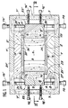
- FIG. 1 firstly shows components already used in the prior art: two main permanent magnets 1 and 1 ′ placed face to face, on either side of an air gap 5, and with the same direction of magnetization , so that the magnetic field lines run through the air gap 5 from one main permanent magnet 1 to the other 1 '.
- the uniformity of the magnetic field inside the air gap 5 is ensured by two pole pieces 2 and 2 ′ of magnetic permeable material and disposed respectively on the faces 20 and 20 ′, of opposite polarities, the main permanent magnets 1 and 1 'overlooking the air gap 5.
- the pole pieces 2 and 2' entirely cover the faces 20 and 20 'along the contour 4.
- the pole pieces are on the contrary narrower than the main permanent magnets 1 and 1 'which they cover and have the outline 4'.
- the device also comprises a yoke 3 of magnetic permeable material which ensures the closing of the magnetic field lines from the permanent magnet 1 'to the permanent magnet main 1. It consists of two support walls 21 and 21 'on the inner surface of which the main permanent magnets 1 and 1' are arranged and which are connected by two connecting walls 22 and 22 '.
- the cylinder head 3 of rectangular section, the main permanent magnets 1 and 1 'parallelepiped and the pole pieces 2 and 2' of constant thickness; the air gap 5 therefore also has a parallelepiped shape.
- the lateral permanent magnets 6 and 6 ' are introduced between the pole pieces 2 and 2' and the main permanent magnets 1 and 1 'so as to come opposite side edges referenced 25, 26 and 25 ', 26' for the pole pieces 2 and 2 'and 27, 28 and 27', 28 'for the main permanent magnets 1 and 1'.
- the height of the lateral permanent magnets 6 and 6 ' is less than the width of the air gap 5, which makes it possible to introduce them there with reduced play and possibly adjust their lateral or vertical position relative to the pole pieces 2 and 2' .
- the lateral permanent magnets 6 and 6 ′ first of all contribute to isolating the air gap 5 from the yoke 3: the magnetic field lines 8 coming from the main permanent magnets 1 and 1 ′ are now curved towards the center of the air gap 5 It can therefore be deduced therefrom that the magnetic energy lost due to the proximity of the connecting walls 22 and 22 ′ is reduced. It is even more so if the main permanent magnets 1 and 1 ′ and / or the lateral magnets 6 and 6 ′ extend beyond the pole pieces 2 and 2 ′ in the direction of the connecting walls 22 and 22 ′.
- the lateral permanent magnets 6 and 6 'contribute by themselves to the strengthening of the magnetic field in the air gap 5 by their field lines 9.
- the adjusting screws 15, 15 ′, 16 and 16 ′ preferably made of non-magnetic material: the vertical screws 15 and 15 ′ fit in threads passing right through the support walls 21 and 21 'respectively, the lateral screws 16 and 16' fit into threads passing right through the connecting walls 22 and 22 'respectively.
- the heads of all these screws are on the outside of the cylinder head 3.
- the side magnets 6 and 6 ' are wedged between opposite vertical screws 15 and 15' which therefore make it possible to vary the clearances between the permanent side magnets 6 and 6 'and the pole pieces 2 and 2 '.
- Their lateral position that is to say the width of the air gap 5, can be modified by acting on the lateral screws 16 and 16 'respectively.
- Figure 2 gives a complementary view of the device according to the invention. It shows that it is not necessary to close the cylinder head 3 by adding magnetic material at its two ends 23 and 23 'to limit the loss of magnetic energy to the outside, which is the case with known devices in medical imaging where only a narrow opening is left to allow the patient to pass into the air gap 5: here a magnetic field of sufficient intensity is available, which makes it possible to adopt a lighter design .
- the total weight in tonnes of the permanent magnets of the ferrite type, of the pole pieces and of the cylinder head of an installation is plotted on the abscissa, and the ordinate the magnetic field in teslas generated in the air gap.
- Curve 30 corresponds to various configurations of an installation without lateral permanent magnets 6 and 6 '; the curve 31 corresponds to the same configurations of an installation further comprising these permanent side magnets 6 and 6 '. It is clear that the weighting involved is more than compensated for by the increase in the magnetic field that is recorded.
- Table I provides some examples of possible embodiments with ferrite type material. The symbols used are found in Figures 1 and 2. TABLE 1 Air gap height (h, in m) 0.5 0.5 0.5 Air gap width (l, in m) 0.75 0.75 0.75 Width of pole pieces (a, in m) 1.25 1.25 1.25 Length of pole pieces (b, in m) 1.375 1.40 1.25 Length of cylinder head (L, in m) 1.62 1.62 2.00 Cylinder head volume (m3) 5.8 6.2 8.6 Installation weight (t) 20 25 35 Magnetic field (T) 0.25 0.275 0.3 Volume of permanent magnets (m3) 2.2 2.8 4.2 Weight of permanent magnets (t) 11 14 21
- the relative variation of the magnetic field is around 10 ⁇ 4 over the width of the air gap 5 (between the lateral permanent magnets 6 and 6 ') and 3.10 ⁇ 4 over its length and height.
- the invention therefore provides an interesting solution for the construction of generators of strong magnetic fields necessary in particular in magnetic resonance imaging; better use of magnetic material can result either in an increase in the intensity of the field, or in a lighter installation.
Landscapes
- Physics & Mathematics (AREA)
- Electromagnetism (AREA)
- Engineering & Computer Science (AREA)
- Power Engineering (AREA)
- Condensed Matter Physics & Semiconductors (AREA)
- General Physics & Mathematics (AREA)
- Magnetic Resonance Imaging Apparatus (AREA)
Claims (4)
- Permanentmagnetsystem, enthaltend ein permeables Magnetjoch (3), das aus zwei Tragwänden (21, 21') gebildet ist, die einander gegenüberstehen und durch zwei Bindungswände (22, 22') miteinander verbunden sind, zwei Hauptpermanentmagnete (1, 1') gleicher Magnetisierungsrichtung, die auf den Tragwänden (21, 21') im Innern des Jochs (3) angeordnet sind und deren einander gegenüberstehende Flächen (20, 20') entgegengesetzte Pole tragen, zwei permeable Magnetplatten (2, 2') auf den einander gegenüberliegenden Flächen (20, 20'), die einen Zwischenraum (5) begrenzen, zwei seitliche Permanentmagnete (6, 6') einer Magnetisierung, die entgegengesetzt zu der der Hauptpermanentmagnete (1, 1') ist und die ebenfalls den Zwischenraum (5) begrenzen und die den Verbindungswänden (22, 22') gegenüberliegend und im Innern des Jochs (3) angeordnet sind, dadurch gekennzeichnet, daß die seitlichen Permanentmagnete (6, 6') sich seitlich zwischen den permeablen Magnetplatten (2, 2') derart erstrecken, daß sie den seitlichen Begrenzungen der Hauptpermanentmagnete (1, 1') und der permeablen Magnetplatten (2,2') gegenüberstehen und daß die Hauptpermanentmagnete (1, 1') über die Platten (2, 2') hinausragen.
- Permanentmagnetsystem nach Anspruch 1, dadurch gekennzeichnet, daß die Tragwände horizontal sind, die Verbindungswände vertikal sind, die Hauptpermanentmagnete und die seitlichen Permanentmagnete quaderförmig sind und der Zwischenraum eine quaderförmige Gestalt hat und an zwei gegenüberliegenden Seiten (23, 23') offen ist.
- Permanentmagnetsystem nach einem der Ansprüche 1 oder 2, dadurch gekennzeichnet, daß die seitlichen Permanentmagnete (6, 6') über die Platten (2, 2') hinausragen.
- Permanentmagnetsystem nach einem der Ansprüche 1 bis 3, dadurch gekennzeichnet, daß es mechanische Einrichtungen (15, 16) aufweist, um die Position der seitlichen Permanentmagnete (6, 6') gegenüber den Platten (2, 2') zu verändern.
Applications Claiming Priority (2)
| Application Number | Priority Date | Filing Date | Title |
|---|---|---|---|
| FR8702851 | 1987-03-03 | ||
| FR8702851A FR2611975B1 (fr) | 1987-03-03 | 1987-03-03 | Systeme d'aimants permanents pour un champ magnetique intense |
Publications (2)
| Publication Number | Publication Date |
|---|---|
| EP0307432A1 EP0307432A1 (de) | 1989-03-22 |
| EP0307432B1 true EP0307432B1 (de) | 1992-10-21 |
Family
ID=9348540
Family Applications (1)
| Application Number | Title | Priority Date | Filing Date |
|---|---|---|---|
| EP88902491A Expired - Lifetime EP0307432B1 (de) | 1987-03-03 | 1988-03-02 | Permanentmagnetsystem zur erzeugung eines intensiven magnetfeldes |
Country Status (5)
| Country | Link |
|---|---|
| US (1) | US4937545A (de) |
| EP (1) | EP0307432B1 (de) |
| JP (1) | JPH01502632A (de) |
| FR (1) | FR2611975B1 (de) |
| WO (1) | WO1988006798A1 (de) |
Families Citing this family (43)
| Publication number | Priority date | Publication date | Assignee | Title |
|---|---|---|---|---|
| US5320103A (en) * | 1987-10-07 | 1994-06-14 | Advanced Techtronics, Inc. | Permanent magnet arrangement |
| US5063934A (en) * | 1987-10-07 | 1991-11-12 | Advanced Techtronics, Inc. | Permanent magnet arrangement |
| US5097240A (en) * | 1989-06-16 | 1992-03-17 | Sumitomo Special Metal Co., Ltd. | Magnetic field generating device for esr system |
| JPH03131234A (ja) * | 1989-07-07 | 1991-06-04 | Sumitomo Special Metals Co Ltd | Mri用磁界発生装置 |
| US5001448A (en) * | 1989-12-18 | 1991-03-19 | General Electric Company | Shield for a magnet |
| US5124651A (en) * | 1990-10-24 | 1992-06-23 | Fonar Corporation | Nuclear magnetic resonance scanners with composite pole facings |
| EP0525246A1 (de) * | 1991-08-01 | 1993-02-03 | Siemens Aktiengesellschaft | Magneteinrichtung mit einem ein magnetisches Streufeld erzeugenden Jochkörper |
| US5278534A (en) * | 1992-09-01 | 1994-01-11 | New York University | Magnetic structure having a mirror |
| JP3123731B2 (ja) * | 1993-02-19 | 2001-01-15 | 株式会社日立メディコ | 磁気共鳴イメージング装置の磁界発生装置 |
| FI933834A7 (fi) * | 1993-09-01 | 1995-03-02 | Picker Nordstar Oy | Magneettikuvauslaitteen napakenkä |
| US5528212A (en) * | 1995-03-09 | 1996-06-18 | Sti Optronics, Inc. | Method and apparatus for control of a magnetic structure |
| US6163154A (en) * | 1997-12-23 | 2000-12-19 | Magnetic Diagnostics, Inc. | Small scale NMR spectroscopic apparatus and method |
| US6835545B2 (en) | 2000-05-08 | 2004-12-28 | President And Fellows Of Harvard College | Methods, products and treatments for diabetes |
| US7271689B1 (en) | 2000-11-22 | 2007-09-18 | Fonar Corporation | Magnet structure |
| US6982620B1 (en) | 2000-11-22 | 2006-01-03 | Fonar Corporation | Magnet structure |
| US7463129B1 (en) | 2000-11-22 | 2008-12-09 | Fonar Corporation | Magnet structure |
| US7248137B1 (en) | 2000-11-22 | 2007-07-24 | Fonar Corporation | Magnet structure |
| US6573817B2 (en) * | 2001-03-30 | 2003-06-03 | Sti Optronics, Inc. | Variable-strength multipole beamline magnet |
| US6686595B2 (en) * | 2002-06-26 | 2004-02-03 | Semequip Inc. | Electron impact ion source |
| KR100827670B1 (ko) * | 2002-06-26 | 2008-05-07 | 세미이큅, 인코포레이티드 | 이온 소스 |
| US6835048B2 (en) * | 2002-12-18 | 2004-12-28 | Varian, Inc. | Ion pump having secondary magnetic field |
| US6859123B2 (en) * | 2003-04-03 | 2005-02-22 | Ge Medical Systems Global Technology Company, Llc | Methods and apparatus for positioning permanent magnetic blocks |
| CN100434038C (zh) * | 2004-03-05 | 2008-11-19 | 西门子(中国)有限公司 | 磁共振成像设备磁场的调节装置 |
| CN100350522C (zh) * | 2004-05-18 | 2007-11-21 | 北京泰杰磁电研究所 | 一种磁共振成像磁体及构成方法 |
| US7319326B2 (en) * | 2004-09-23 | 2008-01-15 | University Of New Brunswick | Sensor and magnetic field apparatus suitable for use in for unilateral nuclear magnetic resonance and method for making same |
| US7833725B2 (en) | 2005-01-06 | 2010-11-16 | President And Fellows Of Harvard College | Mass spectrometric methods and products |
| WO2007117335A2 (en) * | 2006-01-04 | 2007-10-18 | University Of Utah Research Foundation | High field strength magnetic field generation system and associated methods |
| DE602006002264D1 (de) * | 2006-06-01 | 2008-09-25 | Varian Spa | Magnetanordnung für eine Sputter-Ionenpumpe |
| CH697642B1 (de) * | 2007-05-15 | 2008-12-31 | Philippe Saint Ger Ag | Verfahren zur Beeinflussung der magnetischen Kopplung zwischen zwei voneinander beabstandeten Körpern sowie Vorrichtung zur Durchführung des Verfahrens. |
| WO2008145167A1 (de) | 2007-05-31 | 2008-12-04 | Fraunhofer-Gesellschaft zur Förderung der angewandten Forschung e.V. | Magnetanordnung zur erzeugung eines nmr-fähigen homogenen permanentmagnetfeldes |
| JP5012572B2 (ja) * | 2008-02-29 | 2012-08-29 | 富士通株式会社 | マグネトロンスパッタ装置用磁石ユニット |
| US8179220B2 (en) * | 2008-05-28 | 2012-05-15 | Otto Voegeli | Confined field magnet system and method |
| EP2151849B1 (de) * | 2008-08-08 | 2011-12-14 | Agilent Technologies Italia S.p.A. | Vakuum-Pumpsystem, welches mehrere Zerstäubungsionenpumpen enthält |
| GR20090100276A (el) * | 2009-05-15 | 2010-12-21 | Αθανασιος Ανδρεας Νασικας | Μαγνητικη προωθηση με χρηση υπεραγωγων παγιδευσης πεδιου |
| US9068006B2 (en) | 2010-08-25 | 2015-06-30 | President And Fellows Of Harvard College | Glycated CD59 peptides, their preparation, and uses thereof |
| US20130147582A1 (en) * | 2011-11-14 | 2013-06-13 | Nassikas A. Athanassios | Propulsion means using magnetic field trapping superconductors |
| JP5785886B2 (ja) * | 2012-02-27 | 2015-09-30 | アズビル株式会社 | 磁気バネ装置 |
| FR3012263B1 (fr) * | 2013-10-23 | 2015-12-18 | Schneider Electric Ind Sas | Ensemble de prises electriques |
| RU2603348C2 (ru) * | 2015-03-26 | 2016-11-27 | Закрытое акционерное общество "Научно - техническое объединение ПРИБОРСЕРВИС" (ЗАО "НТО ПРИБОРСЕРВИС") | Магниторазрядный насос |
| US11287497B2 (en) | 2016-08-08 | 2022-03-29 | Aspect Imaging Ltd. | Device, system and method for obtaining a magnetic measurement with permanent magnets |
| US11988730B2 (en) | 2016-08-08 | 2024-05-21 | Aspect Imaging Ltd. | Device, system and method for obtaining a magnetic measurement with permanent magnets |
| JP7041122B2 (ja) * | 2016-08-08 | 2022-03-23 | アスペクト イメージング リミテッド | 永久磁石を用いて磁気測定結果を得るためのデバイス、システムおよび方法 |
| DE102023004594B4 (de) * | 2023-11-01 | 2025-05-22 | Helmholtz-Zentrum Berlin für Materialien und Energie Gesellschaft mit beschränkter Haftung | Magnetanordnung zur Beeinflussung eines Strahls geladener Teilchen |
Family Cites Families (7)
| Publication number | Priority date | Publication date | Assignee | Title |
|---|---|---|---|---|
| NL287237A (de) * | 1961-12-27 | |||
| US3437963A (en) * | 1967-06-12 | 1969-04-08 | Varian Associates | Permanent magnet having an enclosing yoke structure with pole aligning means |
| GB1360080A (en) * | 1971-12-22 | 1974-07-17 | Melnikov J A | Magnetic system |
| DE3566185D1 (en) * | 1984-04-11 | 1988-12-15 | Sumitomo Spec Metals | Magnetic field generating device for nmr-ct |
| NL8402250A (nl) * | 1984-07-17 | 1986-02-17 | Philips Nv | Kernspin resonantie apparaat met een rechthoekig permanent magnetische magneet. |
| DE3779715T2 (de) * | 1986-09-27 | 1993-01-28 | Sumitomo Spec Metals | Vorrichtung zur erzeugung eines magnetfeldes fuer rechnergesteuerte tomographie mittels magnetischer kernresonanz. |
| EP1464656A1 (de) * | 2003-04-04 | 2004-10-06 | Ucb S.A. | Emulsionszusammensetzung |
-
1987
- 1987-03-03 FR FR8702851A patent/FR2611975B1/fr not_active Expired - Fee Related
-
1988
- 1988-03-02 US US07/295,218 patent/US4937545A/en not_active Expired - Fee Related
- 1988-03-02 WO PCT/FR1988/000116 patent/WO1988006798A1/fr not_active Ceased
- 1988-03-02 EP EP88902491A patent/EP0307432B1/de not_active Expired - Lifetime
- 1988-03-02 JP JP63502444A patent/JPH01502632A/ja active Pending
Also Published As
| Publication number | Publication date |
|---|---|
| FR2611975A1 (fr) | 1988-09-09 |
| JPH01502632A (ja) | 1989-09-07 |
| EP0307432A1 (de) | 1989-03-22 |
| FR2611975B1 (fr) | 1995-02-17 |
| WO1988006798A1 (fr) | 1988-09-07 |
| US4937545A (en) | 1990-06-26 |
Similar Documents
| Publication | Publication Date | Title |
|---|---|---|
| WO1988006798A1 (fr) | Systeme d'aimants permanents pour un champ magnetique intense | |
| FR2533361A1 (fr) | Aimant permanent multipolaire a intensite de champ reglable | |
| EP2438453A2 (de) | Magnetfeldgenerator und magnetokalorische vorrichtung mit diesem magnetfeldgenerator | |
| WO2015121507A2 (fr) | Cryostat, véhicule de transport à sustentation magnétique et système de transport à sustentation magnétique associés | |
| EP0623939A1 (de) | Davermagnetstruktur zur Herstellung einer stabilen und homogenen magnetischen Induktion in einem bestimmten Raum | |
| FR2987433A1 (fr) | Generateur de champ magnetique pour appareil thermique magnetocalorique | |
| FR2492620A1 (fr) | Dispositif pour le montage de composants electriques et electroniques | |
| FR2562785A1 (fr) | Systeme a aimants permanents destine a l'imagerie par resonance magnetique nucleaire, notamment pour l'examen du corps humain | |
| CH635921A5 (fr) | Four de rechauffage a induction a champ glissant. | |
| FR2649959A1 (fr) | Conditionnement pour produits susceptibles de se degrader lors de leur conservation; procede de preparation sans conservateur de tels produits | |
| FR2568440A1 (fr) | Dispositif a chauffage inductif | |
| EP0688462B1 (de) | Dauermagnetanordnung mit hoher effektivität und mit niedriger streuung | |
| FR3106844A3 (fr) | Profilé métallique pour portail | |
| FR2498497A1 (fr) | Dispositif pour la coulee continue de metaux | |
| FR2566958A1 (fr) | Dispositif generateur de champ magnetique uniforme | |
| FR2489620A1 (fr) | Moteur electrique dont le stator comporte des pieces polaires agencees de facon a empecher le decalage des lignes de force du flux magnetique | |
| FR2583470A1 (fr) | Ecrou | |
| FR2554959A1 (fr) | Electro-aimant comportant un aimant permanent a mouvement de translation | |
| WO2023242647A1 (fr) | Machine électrique à mouvement linéaire | |
| BE456386A (de) | ||
| BE378815A (de) | ||
| BE742111A (de) | ||
| FR2688295A1 (fr) | Profile en u comportant deux elements de raidissement a l'extremite de ses branches et une decoupe dans sa base, et bati comportant un tel profile. | |
| FR2489283A1 (fr) | Aimant de soulevement de charges | |
| EP2553693A1 (de) | Magnetokalorische thermische vorrichtung mit einem magnetfeldgenerator |
Legal Events
| Date | Code | Title | Description |
|---|---|---|---|
| PUAI | Public reference made under article 153(3) epc to a published international application that has entered the european phase |
Free format text: ORIGINAL CODE: 0009012 |
|
| 17P | Request for examination filed |
Effective date: 19881013 |
|
| AK | Designated contracting states |
Kind code of ref document: A1 Designated state(s): DE GB IT NL |
|
| 17Q | First examination report despatched |
Effective date: 19920115 |
|
| GRAA | (expected) grant |
Free format text: ORIGINAL CODE: 0009210 |
|
| AK | Designated contracting states |
Kind code of ref document: B1 Designated state(s): DE GB IT NL |
|
| REF | Corresponds to: |
Ref document number: 3875435 Country of ref document: DE Date of ref document: 19921126 |
|
| ITF | It: translation for a ep patent filed | ||
| GBT | Gb: translation of ep patent filed (gb section 77(6)(a)/1977) |
Effective date: 19930106 |
|
| PLBE | No opposition filed within time limit |
Free format text: ORIGINAL CODE: 0009261 |
|
| STAA | Information on the status of an ep patent application or granted ep patent |
Free format text: STATUS: NO OPPOSITION FILED WITHIN TIME LIMIT |
|
| 26N | No opposition filed | ||
| PGFP | Annual fee paid to national office [announced via postgrant information from national office to epo] |
Ref country code: GB Payment date: 19940301 Year of fee payment: 7 |
|
| PGFP | Annual fee paid to national office [announced via postgrant information from national office to epo] |
Ref country code: DE Payment date: 19940314 Year of fee payment: 7 |
|
| PGFP | Annual fee paid to national office [announced via postgrant information from national office to epo] |
Ref country code: NL Payment date: 19940331 Year of fee payment: 7 |
|
| PG25 | Lapsed in a contracting state [announced via postgrant information from national office to epo] |
Ref country code: GB Effective date: 19950302 |
|
| PG25 | Lapsed in a contracting state [announced via postgrant information from national office to epo] |
Ref country code: NL Effective date: 19951001 |
|
| GBPC | Gb: european patent ceased through non-payment of renewal fee |
Effective date: 19950302 |
|
| NLV4 | Nl: lapsed or anulled due to non-payment of the annual fee |
Effective date: 19951001 |
|
| PG25 | Lapsed in a contracting state [announced via postgrant information from national office to epo] |
Ref country code: DE Effective date: 19951201 |
|
| PG25 | Lapsed in a contracting state [announced via postgrant information from national office to epo] |
Ref country code: IT Free format text: LAPSE BECAUSE OF NON-PAYMENT OF DUE FEES;WARNING: LAPSES OF ITALIAN PATENTS WITH EFFECTIVE DATE BEFORE 2007 MAY HAVE OCCURRED AT ANY TIME BEFORE 2007. THE CORRECT EFFECTIVE DATE MAY BE DIFFERENT FROM THE ONE RECORDED. Effective date: 20050302 |