EP0307617B1 - Richtungsanzeiger für zahnärztliche Röntgenaufnahmen - Google Patents
Richtungsanzeiger für zahnärztliche Röntgenaufnahmen Download PDFInfo
- Publication number
- EP0307617B1 EP0307617B1 EP88112943A EP88112943A EP0307617B1 EP 0307617 B1 EP0307617 B1 EP 0307617B1 EP 88112943 A EP88112943 A EP 88112943A EP 88112943 A EP88112943 A EP 88112943A EP 0307617 B1 EP0307617 B1 EP 0307617B1
- Authority
- EP
- European Patent Office
- Prior art keywords
- indicating
- ray
- supporting member
- film package
- face
- Prior art date
- Legal status (The legal status is an assumption and is not a legal conclusion. Google has not performed a legal analysis and makes no representation as to the accuracy of the status listed.)
- Expired - Lifetime
Links
- 239000007767 bonding agent Substances 0.000 claims description 19
- 210000000214 mouth Anatomy 0.000 claims description 19
- 230000001678 irradiating effect Effects 0.000 claims description 6
- 230000008878 coupling Effects 0.000 description 36
- 238000010168 coupling process Methods 0.000 description 36
- 238000005859 coupling reaction Methods 0.000 description 36
- 230000000694 effects Effects 0.000 description 11
- 210000000887 face Anatomy 0.000 description 7
- 239000000463 material Substances 0.000 description 5
- 101500027295 Homo sapiens Sperm histone HP3 Proteins 0.000 description 4
- 102400000926 Sperm histone HP3 Human genes 0.000 description 4
- 230000003466 anti-cipated effect Effects 0.000 description 2
- 238000010276 construction Methods 0.000 description 2
- 238000003745 diagnosis Methods 0.000 description 2
- 238000007373 indentation Methods 0.000 description 2
- 230000000717 retained effect Effects 0.000 description 2
- 210000003296 saliva Anatomy 0.000 description 2
- 239000007779 soft material Substances 0.000 description 2
- 229920003002 synthetic resin Polymers 0.000 description 2
- 239000000057 synthetic resin Substances 0.000 description 2
- 239000004698 Polyethylene Substances 0.000 description 1
- 238000006073 displacement reaction Methods 0.000 description 1
- 230000002452 interceptive effect Effects 0.000 description 1
- 239000002184 metal Substances 0.000 description 1
- 238000000034 method Methods 0.000 description 1
- 238000012986 modification Methods 0.000 description 1
- 230000004048 modification Effects 0.000 description 1
- -1 polyethylene Polymers 0.000 description 1
- 229920000573 polyethylene Polymers 0.000 description 1
- 239000000126 substance Substances 0.000 description 1
Images


Classifications
-
- G—PHYSICS
- G03—PHOTOGRAPHY; CINEMATOGRAPHY; ANALOGOUS TECHNIQUES USING WAVES OTHER THAN OPTICAL WAVES; ELECTROGRAPHY; HOLOGRAPHY
- G03B—APPARATUS OR ARRANGEMENTS FOR TAKING PHOTOGRAPHS OR FOR PROJECTING OR VIEWING THEM; APPARATUS OR ARRANGEMENTS EMPLOYING ANALOGOUS TECHNIQUES USING WAVES OTHER THAN OPTICAL WAVES; ACCESSORIES THEREFOR
- G03B42/00—Obtaining records using waves other than optical waves; Visualisation of such records by using optical means
- G03B42/02—Obtaining records using waves other than optical waves; Visualisation of such records by using optical means using X-rays
- G03B42/04—Holders for X-ray films
- G03B42/042—Holders for X-ray films for dental applications
-
- A—HUMAN NECESSITIES
- A61—MEDICAL OR VETERINARY SCIENCE; HYGIENE
- A61B—DIAGNOSIS; SURGERY; IDENTIFICATION
- A61B6/00—Apparatus or devices for radiation diagnosis; Apparatus or devices for radiation diagnosis combined with radiation therapy equipment
- A61B6/44—Constructional features of apparatus for radiation diagnosis
- A61B6/4429—Constructional features of apparatus for radiation diagnosis related to the mounting of source units and detector units
- A61B6/4435—Constructional features of apparatus for radiation diagnosis related to the mounting of source units and detector units the source unit and the detector unit being coupled by a rigid structure
-
- A—HUMAN NECESSITIES
- A61—MEDICAL OR VETERINARY SCIENCE; HYGIENE
- A61B—DIAGNOSIS; SURGERY; IDENTIFICATION
- A61B6/00—Apparatus or devices for radiation diagnosis; Apparatus or devices for radiation diagnosis combined with radiation therapy equipment
- A61B6/50—Apparatus or devices for radiation diagnosis; Apparatus or devices for radiation diagnosis combined with radiation therapy equipment specially adapted for specific body parts; specially adapted for specific clinical applications
- A61B6/51—Apparatus or devices for radiation diagnosis; Apparatus or devices for radiation diagnosis combined with radiation therapy equipment specially adapted for specific body parts; specially adapted for specific clinical applications for dentistry
- A61B6/512—Intraoral means
Definitions
- This invention relates to a dental X-ray irradiation indicating device according to the preamble of claim 1.
- a dental or intra-oral X-ray film package (hereinafter referred to only as film package) is positioned inside of the tooth (on the side adjacent the tongue) for an object of photographing, and an X-ray is irradiated upon the tooth from the outside.
- film package a dental or intra-oral X-ray film package
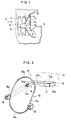
- FIG. 1 is a sectional view of an oral cavity in which the supporting device is used.
- reference symbol 1a and 1b denote each a tooth
- 1a1 and 1b1 denote each an occlusal surface
- 2 denote gums
- 3 a tongue
- 4 a cheek
- Reference numeral 5 denotes a supporting device adapted to be bitten between the teeth 1a and 1b
- the supporting device 5 is made of a comparatively soft or flexible substance and has a shape of a parallelepiped having a rectangular cross section.
- Reference numeral 6 denotes a film package adhered to an end face of the supporting device 5, and 7 an X-ray film enclosed in the film package 6.
- the supporting device 5 and the film package 6 are initially prepared independently of each other. In preparation for X-ray photographing, the supporting device 5 is adhered to a predetermined location of the film package 6, and then the film package 6 is inserted into the oral cavity and positioned at such a position as to allow an X-ray photograph of the tooth 1a to be taken. Then, the supporting device 5 is bitten between the teeth 1a and 1b so as to hold the film package 6 at the position. An X-ray is subsequently irradiated from the outside of the cheek 4 toward the tooth 1a as indicated by an arrow mark X. Consequently, an X-ray image (latent image) of the tooth 1a is produced on the X-ray film 7.
- the film package 6 is then taken out of the oral cavity, and the envelope or cover of the film package 6 is torn away to take out the X-ray film 7.
- the X-ray film 7 is then developed and fixed to produce a visible X-ray image of the tooth 1a on the X-ray film 7.
- EP-A-0 119 300 to wich the preamble of claim 1 refers, describes a dental aiming device provided with a film holding means having a projection formed thereon, a film holder having plural indentations which are selectively fitted on the projection and an alignment ring having three bores which are selectively fitted on an aligning arm.
- This known dental aiming device is also complex in construction and insofar rather expensive. Moreover, it is necessary to choose one of the plural indentations, one of the three bores and the direction of the alignment ring in accordance with the tooth to be X-rayed.
- DE-A-30 06 608 discloses an X-ray source having a conical free end like a cone. Such an X-ray source was used several years ago. In recent years, however, a cylindrical X-ray source having a flat front face has been used predominantly.
- An aiming bar has aiming guides in the form of short lugs. These aiming guides are suited for an old X-ray source, but are not suitable for a cylindrical X-ray source. With the latter X-ray source, the flat front face of the X-ray source must be positioned at a right angle with respect to the lugs. However, this positioning is difficult and requires both time and labour.
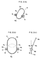
- the dental X-ray irradiation indicating device is generally denoted at 10 and includes a supporting member 11 in the form of a parallelepiped having a rectangular cross section and made of a comparatively soft material such as, for example, foamed polyethylene, sponge or rubber.
- the supporting member 11 has an adhering portion or face 12 for adhering a film package thereto.
- a bonding agent is applied to the adhering portion 12 of the supporting member 11 in advance, and when an X-ray photograph is to be taken, a film package 6 is adhered to the adhering portion 12 as shown in phantom in FIGS. 2 and 4.
- the supporting member 11 further has a pair of upper and lower bite faces or portions 13a and 13b adapted to be bitten by upper and lower opposing teeth when an X-ray photograph is to be taken.
- An arm 14 having a substantially L-shape in plan extends from the supporting member 11.
- the arm 14 has a portion 14a extending laterally from an end of the supporting member 11 and having a face in the common plane with a face of the supporting member 11 opposite the adhering face or portion 12, another portion 14b contiguous to the portion 14a and extending in a direction substantially perpendicular to the portion 14a, and a mounting portion 14c at the other end of the portion 14b.
- An indicating member 15 is removably mounted on the mounting portion 14c of the arm 14.
- the indicating member 15 has a generally ring-like configuration as seen in FIGS. 3(a) to 3(c).
- the indicating member 15 has a first indicating portion or element 15a providing a lower half of a circle, the other upper half of which is shown by a broken line in FIG. 3(b).
- the indicating member 15 further has a second indicating portion or element 15b providing an upper half of another circle, the other lower half of which is shown by a broken line in FIG. 3(b).
- a pair of parallel connecting portions or elements 15c connect the opposite ends of the first and second indicating portions 15a and 15b to each other to complete the indicating member 15.
- a pair of mounting members 16 are securely mounted at or near connecting portions of the indicating member 15 between the first indicating portion 15a and the connecting portions 15c and each has a rectangular through-hole 17 formed therein.
- the indicating member 15 is mounted on the arm 14 with the mounting portion 14c of the latter fitted in the through-hole 17 of one of the mounting members 16 thereon.
- Each of the mounting members 16 has a pair of opposite mounting faces 16a and 16b or 16c and 16d. It is to be noted that the mounting face 16b is opposite the mounting face 16a though not shown in any of FIGS. 2 to 4 but shown in FIG. 5(a).
- the first and second indicating portions 15a and 15b of the indicating member 15 are connected in an inclined relationship to each other by a predetermined angle denoted at ⁇ in FIG. 3(c).
- the plane defined by the second indicating portion 15b is inclined by an angle ⁇ with respect to the plane defined by the first indicating portion 15a (that is, the plane of FIG. 3(b)).
- the angle ⁇ which will be hereinafter described, is shown in a rather exaggerated manner in FIG. 3(c).
- the axes of the through-holes 17 in the mounting members 16 extend perpendicularly to the plane defined by the first indicating portion 15a of the indicating member 15.
- a method of taking an X-ray photograph using the dental X-ray irradiation indicating device 10 of the present invention will be described subsequently with reference to FIGS. 5(a) and 5(b).
- a film package 6 is mounted on the adhering portion 12 of the supporting member 11 as shown in phantom in FIG. 2 by means of a bonding agent applied to the adhering portion 12. Then, one of the mounting members 16 is selected depending upon at which location a tooth for an object of photographing is in a pair of rows of teeth, and the mounting portion 14c of the arm 14 is fitted into the through-hole 17 of the selected mounting member 16 to mount the indicating member 15 on the supporting member 11. In the case shown in FIGS. 5(a) and 5(b), the indicating member 15 is mounted such that the mounting face 16b of the upper mounting member 16 in FIG.
- the film package 6 is inserted into an oral cavity of a patient together with the supporting member 11.
- the film package 6 is positioned inside the tooth 1a (on the side adjacent the tongue) such that a substantially central portion thereof may coincide with the tooth 1a as seen in FIGS.
- the bite portions 13a and 13b of the supporting member 11 are bitten by the teeth 1a and 1b, respectively, so that the film package 6 may be held at the location.
- the film package 6 is held with a certain inclination with respect to a line interconnecting the teeth 1a and 1b, that is, to a vertical line D shown in a long and short dash line in FIG. 5(b) (perpendicular line to the bite portions 13a and 13b).
- the inclination is substantially fixed for each of a tooth for an object of photographing. It is to be noted that, though not specifically shown, the bitten portions 13a and 13b of the supporting member 11 are actually distorted a little because the supporting member 11 is made of a comparatively soft material.
- the portion 14a of the arm 14 extends forwardly outwardly of the oral cavity and then laterally sidewardly farther than the thickness of the cheek 4.
- the second indicating portion 15b of the indicating member 15 is thus positioned in an opposing relationship to a substantially central portion of the film package 6 with a predetermined inclination ⁇ (about one half to the inclination of the film package 6).
- the arm 14 has such a configuration as to attain such positioning of the second indicating portion 15b of the indicating member 15.
- an X-ray irradiating device not shown is positioned such that an irradiating end face thereof may coincide with the plane defined by the second indicating portion 15b of the indicating member 15, and then an X-ray is emitted from the X-ray irradiating device.
- the X-ray is irradiated perpendicularly to the plane of the second indicating member 15b as indicated by a long and short dash line X in FIG. 5(b). Accordingly, an X-ray image (latent image) of the tooth 1a is produced with the substantially same size as the exact size on the X-ray film 7. The reason will be hereinafter described.
- the film package 6 After completion of X-ray irradiation, the film package 6 is taken out of the oral cavity together with the dental X-ray irradiation indicating device 10, and then the indicating member 15 is removed from the arm 14. Then, either after removal of or without removing the film package 6 from the supporting member 11, the X-ray film 7 is taken out of the film package 6, and predetermined developing and fixing operations are made for the X-ray film 7.
- the distance between the points P2' and P3' is given by L/cos ⁇ , and the dimension L/cos ⁇ is greater than the dimension L because cos ⁇ is smaller than 1.
- L/cos ⁇ the dimension of the X-ray film
- the points P2 and P3 are projected at points P2'' and P3'', respectively, on the X-ray film.
- the distance between the points P2'' and P3'' is given by L ⁇ cos ⁇ , and the dimension L ⁇ cos ⁇ is smaller than the dimension L because cos ⁇ is smaller than 1.
- a line E which has an inclination angle equal to one half of the inclination angle ⁇ of the film package 6 as shown in FIG. 6(b).
- An X-ray is thus irradiated in a direction perpendicular to the line E. Consequently, the points P2 and P3 are projected at points P2''' and P3''' on the X-ray film.
- the triangle P1, P3, P3''' defined by a point of intersection between the vertical line D and an extension line of the film package 6 and the points P3 and P3''' is an isosceles triangle.
- the dimension between the points P2''' and P3'' is equal to the dimension L between the points P2 and P3.
- the film package 6 is described held in an inclined position in the foregoing description. Actually, however, the dimensions of various portions of an oral cavity and configurations of rows of teeth and gums are different to some degree among individuals so that the film package 6 may not be inclined but remain in a vertical position. In this instance, if the mounting member 16 is selectively mounted at the mounting portion 14c of the arm 14 such that the first indicating portion 15a may oppose the film package 6, then the plane thereof is parallel to the plane of the film package 6.
- the inclination of the film package 6 substantially depends upon a location of a tooth for an object of photographing in a pair of rows of teeth. Description is given here of mounting of the film package 6 at the mounting portion 14c of the arm 14 when X-ray photographing of teeth at various locations in the rows of the teeth is to be effected. Selections of the mounting faces 16a to 16d of the mounting members 16 and the first and second indicating portions 15a and 15b are given below.
- the indicating member is mounted at the end of the arm extending from the supporting member in an opposing relationship to a film package by way of a selected one of combinations of the first and second indicating portions and the four mounting faces of the two mounting members.
- the indicating member when the film package is in a vertical plane, the indicating member is disposed in parallel to the vertical plane of the film package, but when the film package is in an inclined plane, the indicating member is disposed with an inclination equal to one half of the inclination of the plane of the film package. Accordingly, irradiation of an X-ray can be made readily and accurately and an X-ray image of a tooth can be obtained with the exact size, which will assure an accurate diagnosis and treatment.
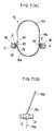
- FIGS. 7(a) and 7(b) there are shown an indicating member and a mounting structure for the same of a dental X-ray irradiation indicating device according to a second embodiment of the present invention.
- like parts or elements are denoted by like reference symbols to those of the first embodiment shown in FIGS. 2 to 4, and overlapping description thereof is omitted herein to avoid redundancy (this also applies to the following description of various embodiments and modifications of the present invention).
- the indicating member denoted at 15 of the dental X-ray irradiation indicating device shown has a pair of projections 20 mounted thereon at or near connecting portions between a first indicating portion 15a and a pair of connecting members 15c thereof.
- a guide plate 21 in the form of a flat plate is secured to an end of each of the projections 20 and extends with substantially equal spans in the opposite directions from the end of the projection 20.
- each of a pair of mounting members 16 has a pair of L-shaped holding pieces 22 formed at a pair of upper and lower ends of a side face thereof, and a slot 23 is thus defined by the side face and the holding pieces 22 of the mounting member 16.
- the mounting plate 16 can thus be mounted readily on the indicating member 15 by fitting one of the guide plates 21 into the slot 23 thereof and can be adjusted relative to the indicating member 15 by slidably moving the guide plate 21 in the slot 23 thereof.
- the conditions of the gums, rows of teeth, lips, cheeks and so on are different to some degree among individuals as described hereinabove. Due to such differences, the position of the mounting portion 14c of the arm 14 (refer to FIGS. 2 to 4) when the supporting member 11 is held in a bitten condition in an oral cavity in order to effect X-ray photographing is different more or less among individuals. Further, even with a same person, the position of the mounting portion 14c of the arm 14 may be different more or less depending upon a tooth for an object of photographing. There is the possibility, therefore, that, when a mounting member 16 is mounted on the mounting portion 14c of the arm 14, the indicating member 15 may be contacted with and distorted by an outer face of a cheek.
- the mounting member 16 can be slidably moved back and forth on the guide plate 21 relative to the indicating member 15, where there is the possibility that the indicating member 15 may be contacted with a cheek, the indicating member 15 can be positioned in a spaced relationship from the cheek by slidably displacing the mounting member 16 toward the cheek and mounting the thus adjusted mounting member 16 at the mounting portion 14c of the arm 14.
- the distance between the indicating member 15 and the cheek can also be adjusted suitably by such sliding displacement of the mounting member 16 on the guide plate 21.
- the mounting members 16 may be secured reversely to ends of guide plates while guide slots or guide holes for receiving the guide plates therein are formed in the indicating member 15.
- the mounting members can be displaced in the forward and backward directions with respect to the indicating member, not only similar effects to those of the preceding first embodiment can be anticipated, but also the indicating member can be held in a suitably spaced relationship from an outer face of a cheek.
- FIGS. 8(a) to 8(d) there are shown an indicating member and a mounting structure for the same of a dental X-ray irradiation indicating device according to a third embodiment of the present invention.
- the indicating member 15 of the dental X-ray irradiation indicating device shown has a pair of mounting plates 25 mounted thereon at or near connecting portions between a first indicating portion 15a and a pair of connecting portions 15c thereof.
- a pin 26 is implanted on each of the mounting plates 25, and a pivotal member 27 is mounted for pivotal motion on the pin 27.
- the pivotal member 26 has a mounting member 16 secured to an end thereof.
- FIG. 8(a) the left-hand side pivotal member 27 is shown in its horizontal position while the right-hand side pivotal member 27 is shown in its upwardly pivoted position.
- Each of the mounting plates 25 has, as particularly seen in FIGS. 8(c) and 8(d), up to four grooves 29a, 29b, 29c and 29d formed in vertical and horizontal directions in an angularly spaced relationship by 90 degrees in a wall thereof.
- the pin 26 is provided at a crossing location of the grooves 29a to 29d on the mounting plate 25 and has an enlarged head portion 26a formed at an end thereof and a diametrical slit 26b formed therein.
- each of the pivotal plates 27 has a projection 28 provided at a location thereon near a hole in which the pin 26 is fitted.
- the pivotal member 27 In order to fit a pivotal member 27 onto a pin 26, the pivotal member 27 is pressed at the hole thereof strongly against the pin 26. Consequently, the pin 26 is distorted to reduce the slit 26b thereof so that the diameter of the enlarged head portion 26a is reduced to allow the pin 26 to be fitted into the hole of the pivotal member 27. After the pivotal member 27 is fitted onto the pin 26, the pin 26 is restored to its original shape expanding the slit 26b to expand the enlarged head portion 26a. Consequently, the pivotal member 27 is thereafter prevented from coming off from the pin 26.
- the projection 28 thereon will slidably move on a surface of the mounting plate 25 until it is fitted into one of the grooves 29a to 29d in the mounting plate 25, but if the pivotal member 27 is pivoted further, the projection 28 thereon will be removed from the one groove and then fitted into an adjacent next one of the grooves 29a to 29d. With the projection 28 thus fitted in one of the grooves 29a to 29d, the pivotal member 27 is retained at the position.
- the dental X-ray irradiation indicating device of the present embodiment can prevent possible contact of the indicating member 15 with a cheek similarly as in the preceding embodiment.
- one of the pivotal members 27 to which the mounting member 16 to be mounted at the mounting portion 14c of the arm 14 is secured is pivoted until the projection 28 thereon is fitted into the groove 29a or 29d of the mounting plate 25 to retain the pivotal member 27 at its horizontal position.
- the mounting member 16 is then mounted onto the mounting portion 14c of the arm 14.
- the indicating member 15 can be held at a position spaced from an outer face of a cheek.
- the pivotal members are mounted for pivotal motion on the indicating member and the mounting members are secured to ends of the pivotal members, not only similar effects to those of the second embodiment can be attained, but also the pivotal members and the mounting members can be prevented from interfering with some other elements upon photographing or upon storage of the indicating member if an unnecessary one of the pivotal members is retained at the upwardly pivoted position.
- FIGS. 9(a) to 9(d) there are shown an indicating member and a mounting structure for the same of a dental X-ray irradiation indicating device according to a fourth embodiment of the present invention.
- the indicating member denoted at 15' of the dental X-ray irradiation indicating device shown corresponds to the indicating member 15 of the first to third embodiments described hereinabove.
- the indicating member 15' of the present embodiment is different from the indicating member 15 of the preceding embodiments in that a first indicating portion 15a and a pair of connecting members 15c thereof are coupled to each other by a pair of pivotally connecting means 31 and 32.
- the pivotally connecting means 31 includes, as shown in FIG. 9(b), a plate-formed member 31c secured to or molded in an integral relationship with one of the connecting members 15c, another plate-formed member 31a secured to or molded in an integral relationship with one end of the first indicating portion 15a, and a pin 31p for connecting the plate-formed members 31c and 31a for pivotal motion relative to to each other.
- the other pivotally connecting means 32 includes, as shown in FIG.
- a plate-formed member 32c secured to or molded in an integral relationship on the other connecting member 15c, another plate-formed member 32a secured to or molded in an integral relationship on the other end of the first indicating portion 15a, and a screw 32b for securing the plate-formed members 32c and 32a to each other.
- a nut 32n is secured to the end of the screw 32b.
- the plate-formed member 32c has a mark 33a applied at an end portion thereof while several graduations 33b are applied to the other plate-formed member 32a of the pivotally connecting means 32 in an opposing relationship to the mark 33a as shown in FIG. 9(d).
- the plane defined by the first and second indicating portions 15a and 15b may not always be inclined by an angle equal to one half of such an inclination angle ⁇ of the film package 6 as shown in FIG. 6(b).
- a desired degree of accuracy may not always be attained in X-ray photographing.
- the inclination of the indicating member 15 can be adjusted readily in such an instance.
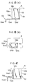
- FIGS. 10(a) and 10(b) there is shown a example of coupling structure between a supporting member and an arm.
- the coupling structure shown includes a supporting member 131 composed of a single member 132.
- the member 132 has a pair of bitten portions or faces 132a and 132b, and an adhering face 132c for a film package 6.
- the member 132 further has a bonding agent layer 132d applied to a face thereof opposite the adhering face 132c.
- the coupling structure further includes an arm 134 formed as a unitary member composed of a portion 134a extending from the supporting member 131, another portion 134b contiguous to the portion 134a and extending substantially in a direction perpendicular to the portion 134a, and a plate-formed portion 134d adhered to the bonding agent layer 132d of the member 132 of the supporting member 131. It is to be noted that a portion of the arm 134 at which an indicating member is to be mounted on the arm 134 is omitted in FIGS. 10(a) and 10(b) (this also applies to the following examples of coupling structure).
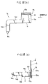
- FIG. 11 shows an example of coupling structure between a supporting member and an arm.
- the coupling structure shown includes a supporting member 141 composed of a single member 142.
- the member 142 has a bitten portion or face 142a and another bitten portion or face not shown, and an adhering face 142c for a film package 6.
- the member 142 further has a bonding agent layer 142d applied to a face thereof perpendicular to the adhering face 142c.
- the coupling structure further includes an arm 144 formed as a unitary member composed of a portion 144a extending from the supporting member 141, another portion 144b contiguous to the portion 144a and extending substantially in a direction perpendicular to the portion 144a, and a plate-formed portion 144d adhered to the bonding agent layer 142d of the member 142 of the supporting member 141. Comparing with the coupling structure shown in FIGS. 10(a) and 10(b), the present coupling structure is different in location of the face of the member 142 of the supporting member 141 to which the plate-formed portion 144d of the arm 144 is adhered. The present coupling structure thus presents similar effects to those of the seventh coupling structure.
- the coupling structure shown includes a supporting member 151 composed of a single member 152.
- the member 152 has a bitten portion or face 152a and another bitten portion or face not shown, and an adhering face 152c for a film package 6.
- the member 152 further has a bonding agent layer 152d applied to a face thereof perpendicular to the adhering face 152c.
- the coupling structure further includes an arm 154 formed as a unitary member composed of a portion 154a extending from the supporting member 151, another portion 154b contiguous to the portion 154a and extending substantially in a direction perpendicular to the portion 154a, and a plate-formed portion 154d adhered to the bonding agent layer 152d of the member 152 of the supporting member 151.
- the present coupling structure is different in that the face of the member 152 of the supporting member 151 to which the plate-formed portion 154d of the arm 154 is secured is located at the opposite position to that in the coupling structure of Fig. 11 and the portion 154a of the arm 154 extends on and across a face of the member 152 of the supporting member 151 opposite the adhering face 152c.
- the present coupling structure thus presents similar effects to those of the eighth coupling structure.
- the coupling structure shown includes a supporting member 151' composed of a single member 152.
- the supporting member 151' is different from the supporting member 151 of the coupling structure shown in FIG. 12 in that it has an additional second bonding agent layer 152d' applied to a face thereof opposing an adhering face 152c thereof.
- An arm 154' of the present coupling structure is also different from the arm 154 of the coupling structure shown in FIG. 12 in that it has a second plate-formed portion 154d' contiguous to a first plate-formed portion 154d thereof and extending substantially in a direction perpendicular to the first plate-formed portion 154d.
- the second plate-formed portion 154d' of the arm 154' is adhered to the bonding agent layer 152d of the member 152 of the supporting member 151'.
- the coupling structure shown includes a supporting member 161 composed of a single member 162 having a bitten portion or face 162a.
- the member 162 further has a bonding agent layer 162d applied to a side face thereof.
- An arm 164 of the coupling structure is composed of a portion 164a extending from the supporting member 161, another portion 164b contiguous to the portion 164a and extending substantially in a direction perpendicular to the portion 164a, a plate-formed portion 164d adhered to the bonding agent layer 162d of the supporting member 161, and a bonding agent layer 164e applied to the plate-formed portion 164d.
- a film package 6 is adapted to be applied to the bonding agent layer 164e of the arm 164.
- the present coupling structure also presents similar effects to those of the coupling structure shown in FIGS. 10(a) and 10(b).
- the material of the arm is not limited to a synthetic resin and may otherwise be a metal or some other suitable material.
- a film package 6 is enclosed in an envelope 6'.
- the envelope 6' is made of a softer material than that of an outer package member or cover of the film package 6.
- Such an outer package member of the film package 6 is limited in flexibility due to the necessity for interruption of light and also for protection of an X-ray film. Therefore, when the film package 6 is inserted into an oral cavity, it will in most cases give a disagreeable feeling to the patient due to lack in flexibility. Besides, upon X-ray photographing, saliva will always apply to the film package 6.
- the saliva on the film package 6 may apply to the dentist, which will give a disagreeable feeling to the dentist and besides is not preferable for sanitation. From those reasons, in most cases a film package 6 is enclosed in an envelope 6' made of a very flexible material and inserted in this condition into an oral cavity of a patient.
- a bonding agent layer 170 is applied to an adhering portion or face 12 of a supporting member 11.
- a supporting element 171 for supporting an envelope 6' and a film package 6 in the envelope 6' thereon is formed separately from the supporting member 11 and applied to the bonding agent layer 170 of the supporting member 11.
- the supporting element 171 is composed of a U-shaped member 171a made of a synthetic resin having a suitable elasticity.
- the U-shaped member 171a has a wall 171b adapted to be applied to the bonding agent layer 170 of the supporting member 11, and a supporting portion 171c for cooperating with the wall 171b to hold therebetween an envelope 6' and a film package 6 in the envelope 6'.
- the wall 171b of the supporting element 171 is applied to the adhering portion 12 of the arm 11 to which the film package 6 is to be primarily adhered. Consequently, the supporting element 171 is secured to the supporting member 11.
- the envelope 6' in which the film package 6 is enclosed is subsequently inserted into the supporting portion 171c of the supporting element 171. Since the U-shaped member 171a of the supporting element 171 has a suitable elasticity, the envelope 6' inserted in this manner is held firmly by the supporting portion 171c of the supporting element 171 so that the film package 6 is supported with certainty on the supporting element 171.
- the supporting element is described composed of a U-shaped member, it may have any other configuration only if a film package or an envelope enclosed in an envelope can be fixed firmly thereto.
- the supporting member and the arm are shown formed as a unitary member, they may otherwise be formed as separate members. Meanwhile, naturally a film package 6 may otherwise be adhered directly to the supporting element 171.
- an indicating member is described formed either as a ring or as a substantially circular plate member, it is not limited to the specific members and may be a member of any other configuration only if it is made of a material which transmits an X-ray therethrough.
- plate members of various configurations, plate members in which openings of various shapes are formed and cross-shaped bar members may be used for the indicating member.
- a dental X-ray irradiation indicating device comprises a supporting member, an arm means extending from the supporting member, and an indicating member mounted on the arm means by way of a mounting member, whereby the indicating member is positioned in an opposing relationship to an intra-oral X-ray film package which is held in a predetermined angular position in an oral cavity of a patient. Therefore, it is only necessary to irradiate an X-ray with reference to the indicating member. Accordingly, irradiation of an X-ray can be effected readily and accurately with a simple construction. Besides, an X-ray image of an object of photographing can be obtained with a substantially same size on an X-ray film.
Landscapes
- Health & Medical Sciences (AREA)
- Life Sciences & Earth Sciences (AREA)
- Engineering & Computer Science (AREA)
- Medical Informatics (AREA)
- General Health & Medical Sciences (AREA)
- Physics & Mathematics (AREA)
- Nuclear Medicine, Radiotherapy & Molecular Imaging (AREA)
- Heart & Thoracic Surgery (AREA)
- High Energy & Nuclear Physics (AREA)
- Veterinary Medicine (AREA)
- Oral & Maxillofacial Surgery (AREA)
- Optics & Photonics (AREA)
- Pathology (AREA)
- Radiology & Medical Imaging (AREA)
- Biomedical Technology (AREA)
- Biophysics (AREA)
- Molecular Biology (AREA)
- Surgery (AREA)
- Animal Behavior & Ethology (AREA)
- Public Health (AREA)
- General Physics & Mathematics (AREA)
- Dentistry (AREA)
- Apparatus For Radiation Diagnosis (AREA)
Claims (5)
- Vorrichtung (10) zum Halten einer intra-oralen Röntgenfilm-Packung in einer Mundhöhle eines Patienten, umfassend
ein Tragelement (11, 161, 171) mit einem Filmbefestigungsabschnitt (12), an dem eine intra-orale Röntgenfilm-Packung (6) zu befestigen ist und einem Beißabschnitt (13, 162), der durch die Zähne des Patienten gehalten wird,
ein im wesentlichen L-förmiges Armelement (14, 164), das sich von dem Tragelement (11, 161, 171) aus erstreckt und nach außen aus der Mundhöhle gerichtet ist, wenn der Beißabschnitt (13, 162) durch die Zähne gehalten wird,
ein Anzeigeelement (15) mit einem ersten Anzeigeabschnitt (15a), der eine erste Ebene vorgibt, senkrecht zu der die Röntgenstrahlen zu richten sind, einen Verbindungsabschnitt (15c) und zwei Befestigungsteile (16), die am oder nahe an dem Verbindungsabschnitt (15c) und am oder nahe an dem Anzeigeabschnitt (15a) angebracht sind, wobei diese Befestigungsteile (16) so ausgestaltet sind, daß das Anzeigeelement (15) an dem Armelement (14) selektiv in einer vorbestimmten ersten Ausrichtung oder in einer zweiten Ausrichtung entsprechend einem Spiegelbild bezüglich der ersten Ausrichtung abnehmbar angebracht werden kann, wodurch sich die erste Ebene parallel zu der Ebene der Filmpackung (6) erstreckt, die an dem Filmbefestigungsabschnitt (12) des Tragelementes (11) angebracht wird, wenn das Anzeigeelement (15) an dem Armelement (14, 164) in der vorbestimmten ersten Ausrichtung oder in der zweiten Ausrichtung durch diese Befestigungsteile (16) angebracht ist,
dadurch gekennzeichnet,
daß das Anzeigeelement (15) weiterhin einen zweiten Anzeigeabschnitt (15b) umfaßt, der eine zweite Ebene vorgibt, wobei die senkrechte auf dieser eine alternative Richtung für das Anlegen von Röntgenstrahlen wiedergibt, die zweite Ebene sich in einem vorbestimmten Winkel (α) bezüglich der ersten Ebene erstreckt und wobei die Filmpackung (6) bezüglich des Tragelementes (11) geneigt werden kann, so daß sie im wesentlichen parallel zu der zweiten Ebene liegt, damit ein zu erstellendes Röntgenbild auch auf den Abschnitten der Mundhöhle möglich ist, auf denen das Zahnfleisch dazwischenliegt, wenn sich die Filmpackung (6) in einer nicht geneigten Stellung befindet. - Vorrichtung nach Anspruch 1,
wobei das Armelement (14) integral mit dem Tragelement (11) ausgebildet ist. - Vorrichtung nach Anspruch 1,
wobei das Armelement (164) eine erste Fläche (164d) zum Befestigen an einem Befestigungsabschnitt (162d) des Tragelementes (161), eine zweite Fläche (164e), an der eine intra-orale Röntgenfilm-Packung (6) zu befestigen ist, und
einen Armabschnitt (164b) aufweist, der sich nach außen aus der Mundhöhle erstreckt, wenn die erste Seite des Armelementes an dem Befestigungsabschnitt (162d) des Tragelementes befestigt ist und der Beißabschnitt (162a) des Tragelementes durch die Zähne des Patienten gehalten wird. - Vorrichtung nach Anspruch 1 oder 2,
wobei das Tragelement (11) einen Haftabschnitt (12) aufweist, an dem eine Schicht eines Bindemittels (170) aufgebracht ist, und ein Halteelement (171) vorgesehen ist, das eine Haftfläche (171b) zum Anbringen durch Haften an dem Haftabschnitt (12) des Tragelementes (11) und einen Halteabschnitt (171c) zum Halten der intra-oralen Röntgenfilm-Packung (6) daran aufweist. - Vorrichtung nach Anspruch 4,
wobei das Halteelement (171) ein Halter (171a) mit einem U-förmigen Querschnitt ist.
Applications Claiming Priority (14)
| Application Number | Priority Date | Filing Date | Title |
|---|---|---|---|
| JP140137/87U | 1987-09-16 | ||
| JP14013787 | 1987-09-16 | ||
| JP148207/87U | 1987-09-30 | ||
| JP14820787 | 1987-09-30 | ||
| JP1988002561U JPH0451777Y2 (de) | 1987-09-16 | 1988-01-14 | |
| JP2561/88U | 1988-01-14 | ||
| JP1988007130U JPH01112808U (de) | 1987-09-30 | 1988-01-25 | |
| JP7130/88U | 1988-01-25 | ||
| JP2812588 | 1988-03-04 | ||
| JP28125/88U | 1988-03-04 | ||
| JP40441/88U | 1988-03-29 | ||
| JP1988040441U JPH0217114U (de) | 1988-03-04 | 1988-03-29 | |
| JP1988042917U JPH0440648Y2 (de) | 1988-04-01 | 1988-04-01 | |
| JP42917/88U | 1988-04-01 |
Publications (3)
| Publication Number | Publication Date |
|---|---|
| EP0307617A2 EP0307617A2 (de) | 1989-03-22 |
| EP0307617A3 EP0307617A3 (en) | 1989-12-06 |
| EP0307617B1 true EP0307617B1 (de) | 1994-10-26 |
Family
ID=27563193
Family Applications (1)
| Application Number | Title | Priority Date | Filing Date |
|---|---|---|---|
| EP88112943A Expired - Lifetime EP0307617B1 (de) | 1987-09-16 | 1988-08-09 | Richtungsanzeiger für zahnärztliche Röntgenaufnahmen |
Country Status (4)
| Country | Link |
|---|---|
| US (1) | US4949370A (de) |
| EP (1) | EP0307617B1 (de) |
| CA (1) | CA1295429C (de) |
| DE (1) | DE3851929T2 (de) |
Cited By (1)
| Publication number | Priority date | Publication date | Assignee | Title |
|---|---|---|---|---|
| CN1650228B (zh) * | 2002-04-01 | 2012-03-07 | 珍妮弗·A·迪德里希 | 牙科所用的射线定位装置 |
Families Citing this family (27)
| Publication number | Priority date | Publication date | Assignee | Title |
|---|---|---|---|---|
| US5001738A (en) * | 1989-04-07 | 1991-03-19 | Brooks Jack D | Dental X-ray film holding tab and alignment method |
| EP0397599B1 (de) * | 1989-05-10 | 1994-03-09 | Rolf M. Dr. Klauser | Röntgenfilmhalter-Satz für die Aufnahme von Röntgenbildern eines ganzen Zahnes |
| US5113424A (en) * | 1991-02-04 | 1992-05-12 | University Of Medicine & Dentistry Of New Jersey | Apparatus for taking radiographs used in performing dental subtraction radiography with a sensorized dental mouthpiece and a robotic system |
| US5327477A (en) * | 1992-12-29 | 1994-07-05 | Paul Levy | Film positioning system for dental X-ray procedures |
| US5629972A (en) * | 1993-05-18 | 1997-05-13 | Research Foundation Of State University Of New York | Intraoral radiograph alignment device |
| US5513240A (en) * | 1993-05-18 | 1996-04-30 | The Research Foundation Of Suny | Intraoral radiograph alignment device |
| US5416822A (en) * | 1994-08-29 | 1995-05-16 | Kunik; Randall L. | Device for registering a dental radiograph having distortion measuring capability and method for using the same |
| DE29508129U1 (de) * | 1995-05-17 | 1995-08-31 | Kentzler-Kaschner Dental GmbH, 73479 Ellwangen | Filmhalter für ein zahnmedizinisches Röntgengerät |
| ES2120883B1 (es) * | 1996-02-23 | 1999-06-01 | Cueto Suarez Manuel | Nuevo fondo para la fotografia intraoral aplicable en odontoestomatologia. |
| EP1117330A4 (de) * | 1998-09-29 | 2003-09-24 | Univ Texas | Dentale röntgenzielvorrichtung für longitudinale radiographische analyse |
| US6343875B1 (en) | 1999-06-30 | 2002-02-05 | Dentsply Research & Development Corp. | Modular bite block and sensor holder apparatus for dental x-ray procedures |
| DE60041069D1 (de) | 1999-10-08 | 2009-01-22 | Gendex Corp | Positioniervorrichtung zur transversalen zahnärztlichen röntgentomographie |
| US7008104B2 (en) * | 2003-07-18 | 2006-03-07 | Cochran Phillip E | Dental x-ray film positioning instrument |
| US7311440B2 (en) * | 2004-03-31 | 2007-12-25 | Cyber Medical Imaging, Inc. | Anatomically conforming intraoral dental radiographic sensor |
| US6974253B2 (en) * | 2004-04-12 | 2005-12-13 | Instrumentarium Corp. | Connection between X-ray sensor and holder |
| US7261463B2 (en) * | 2004-07-16 | 2007-08-28 | Becht Darrell A | Method and apparatus for supporting a dental X-ray sensor |
| US7226208B2 (en) * | 2004-11-11 | 2007-06-05 | Schmulenson Harold K | Holder for an x-ray sensing device |
| US7382860B2 (en) * | 2005-02-23 | 2008-06-03 | Interactive Diagnostic Imaging, Inc. | Image capture device and methods |
| US20080298543A1 (en) * | 2005-02-23 | 2008-12-04 | Razzano Michael R | Image capture device and methods |
| US7194064B2 (en) * | 2005-02-23 | 2007-03-20 | Interactive Diagnostic Imaging, Inc. | Image capture device and methods |
| US7425095B2 (en) * | 2005-08-23 | 2008-09-16 | Harold K. Schmulenson | Instrument for holding and aligning an x-ray sensing device |
| US7819579B2 (en) * | 2007-11-26 | 2010-10-26 | Schmulenson Harold K | Radiation sensing device and holder |
| US8142074B2 (en) | 2007-11-26 | 2012-03-27 | Schmulenson Harold K | Radiation sensing device and holder |
| US8333507B2 (en) * | 2008-12-29 | 2012-12-18 | Schmulenson Harold K | Holder for radiation sensing device |
| US20140270068A1 (en) * | 2013-03-15 | 2014-09-18 | Zuma Dental, LLC | Imaging system and method |
| CN106466190A (zh) * | 2015-08-18 | 2017-03-01 | 万得福牙材有限公司 | 咬合持片装置 |
| US20180014799A1 (en) * | 2016-07-18 | 2018-01-18 | Harold K. Schmulenson | System configured to hold a radiation sensing device in a variety of positions |
Family Cites Families (10)
| Publication number | Priority date | Publication date | Assignee | Title |
|---|---|---|---|---|
| US2034049A (en) * | 1936-03-17 | Indicative apparatus for obtaining | ||
| US1923669A (en) * | 1932-08-22 | 1933-08-22 | Henry H Harrison | Dental X-ray focusing instrument |
| US2090933A (en) * | 1933-05-05 | 1937-08-24 | Leonard M Bolin | Device for positioning dental X-ray films |
| US2127502A (en) * | 1936-08-27 | 1938-08-23 | Weal Andre De | Dental film holder |
| US4057732A (en) * | 1976-02-04 | 1977-11-08 | Rolf Marcus Klauser | Film holder for bite-wing radiographs |
| CH639263A5 (de) * | 1979-03-09 | 1983-11-15 | Identoflex Ag | Vorrichtung zur halterung roentgenstrahlenempfindlicher filme bei odontologischen roentgenaufnahmen. |
| SE453047B (sv) * | 1981-11-04 | 1988-01-11 | Trollhetteplast Forseljnings A | Hjelpmedel for utforande av tandrontgenundersokningar |
| US4554676A (en) * | 1983-03-16 | 1985-11-19 | The S. S. White Company | Dental aiming device |
| NL8302144A (nl) * | 1983-06-15 | 1985-01-02 | Cuykse Medische Centrale B V | Inrichting voor het maken van een beeld van een kaakdeel. |
| US4815117A (en) * | 1987-09-02 | 1989-03-21 | Waldo Patricia J | Cushioning bite plate adapter for x-ray film holder |
-
1988
- 1988-08-09 EP EP88112943A patent/EP0307617B1/de not_active Expired - Lifetime
- 1988-08-09 DE DE3851929T patent/DE3851929T2/de not_active Expired - Fee Related
- 1988-08-10 CA CA000574309A patent/CA1295429C/en not_active Expired - Fee Related
- 1988-08-10 US US07/230,513 patent/US4949370A/en not_active Expired - Fee Related
Cited By (1)
| Publication number | Priority date | Publication date | Assignee | Title |
|---|---|---|---|---|
| CN1650228B (zh) * | 2002-04-01 | 2012-03-07 | 珍妮弗·A·迪德里希 | 牙科所用的射线定位装置 |
Also Published As
| Publication number | Publication date |
|---|---|
| DE3851929D1 (de) | 1994-12-01 |
| EP0307617A2 (de) | 1989-03-22 |
| DE3851929T2 (de) | 1995-02-23 |
| CA1295429C (en) | 1992-02-04 |
| US4949370A (en) | 1990-08-14 |
| EP0307617A3 (en) | 1989-12-06 |
Similar Documents
| Publication | Publication Date | Title |
|---|---|---|
| EP0307617B1 (de) | Richtungsanzeiger für zahnärztliche Röntgenaufnahmen | |
| US3473026A (en) | Dental instruments for standardizing the bisecting-angle technique for periapical radiography | |
| US5289522A (en) | Dental X-ray aiming device | |
| US4507798A (en) | Device for performing X-ray examinations of the teeth | |
| US5327477A (en) | Film positioning system for dental X-ray procedures | |
| US6190042B1 (en) | Dental x-ray aiming device for longitudinal radiographic analysis | |
| EP1194811B1 (de) | Positioniervorrichtung für verschiedene dentale Röntgenaufnahmeverfahren mit einer Sensorhalterung und unterschiedlichen Bi blöcken modularen Designs | |
| US5001738A (en) | Dental X-ray film holding tab and alignment method | |
| US5119410A (en) | Rotating poisitioning instrument for intra oral radiography | |
| US4295050A (en) | Instrument for positioning an X-ray camera in dental X-ray photography | |
| EP0151587B1 (de) | Vorrichtung zum aufnehmen eines bildes eines kinnbackenteils | |
| US5629972A (en) | Intraoral radiograph alignment device | |
| US7056015B2 (en) | Intraoral dental radiology positioning device | |
| US4075494A (en) | Orally receptive holder for a dental x-ray film paquette | |
| US7172339B2 (en) | Intraoral dental radiology positioning device for use with aiming ring | |
| US4633493A (en) | Dental instrument for optimal positioning of an X-ray film support, especially for use in the X-raying of front teeth | |
| JPH0614735Y2 (ja) | 上顎臼歯用のx線撮影具 | |
| US20050190889A1 (en) | X-ray film holder | |
| US20030185347A1 (en) | Intraoral dental radiology positioning device | |
| JPH0117297Y2 (de) | ||
| JPH0451777Y2 (de) | ||
| JPH10314165A (ja) | 歯科用x線断層撮影装置の歯列位置決め装置及び歯列 位置決め方法 | |
| WO1981002973A1 (en) | X-ray film holder for use in making dental radiographs | |
| JPH0440648Y2 (de) | ||
| JPH0415208Y2 (de) |
Legal Events
| Date | Code | Title | Description |
|---|---|---|---|
| PUAI | Public reference made under article 153(3) epc to a published international application that has entered the european phase |
Free format text: ORIGINAL CODE: 0009012 |
|
| AK | Designated contracting states |
Kind code of ref document: A2 Designated state(s): DE FR GB IT |
|
| PUAL | Search report despatched |
Free format text: ORIGINAL CODE: 0009013 |
|
| AK | Designated contracting states |
Kind code of ref document: A3 Designated state(s): DE FR GB IT |
|
| 17P | Request for examination filed |
Effective date: 19900518 |
|
| 17Q | First examination report despatched |
Effective date: 19920702 |
|
| GRAA | (expected) grant |
Free format text: ORIGINAL CODE: 0009210 |
|
| ITF | It: translation for a ep patent filed | ||
| AK | Designated contracting states |
Kind code of ref document: B1 Designated state(s): DE FR GB IT |
|
| REF | Corresponds to: |
Ref document number: 3851929 Country of ref document: DE Date of ref document: 19941201 |
|
| ET | Fr: translation filed | ||
| PLBE | No opposition filed within time limit |
Free format text: ORIGINAL CODE: 0009261 |
|
| STAA | Information on the status of an ep patent application or granted ep patent |
Free format text: STATUS: NO OPPOSITION FILED WITHIN TIME LIMIT |
|
| 26N | No opposition filed | ||
| PGFP | Annual fee paid to national office [announced via postgrant information from national office to epo] |
Ref country code: FR Payment date: 19980729 Year of fee payment: 11 |
|
| PGFP | Annual fee paid to national office [announced via postgrant information from national office to epo] |
Ref country code: GB Payment date: 19980806 Year of fee payment: 11 |
|
| PGFP | Annual fee paid to national office [announced via postgrant information from national office to epo] |
Ref country code: DE Payment date: 19980923 Year of fee payment: 11 |
|
| PG25 | Lapsed in a contracting state [announced via postgrant information from national office to epo] |
Ref country code: GB Free format text: LAPSE BECAUSE OF NON-PAYMENT OF DUE FEES Effective date: 19990809 |
|
| GBPC | Gb: european patent ceased through non-payment of renewal fee |
Effective date: 19990809 |
|
| PG25 | Lapsed in a contracting state [announced via postgrant information from national office to epo] |
Ref country code: FR Free format text: LAPSE BECAUSE OF NON-PAYMENT OF DUE FEES Effective date: 20000428 |
|
| PG25 | Lapsed in a contracting state [announced via postgrant information from national office to epo] |
Ref country code: DE Free format text: LAPSE BECAUSE OF NON-PAYMENT OF DUE FEES Effective date: 20000601 |
|
| REG | Reference to a national code |
Ref country code: FR Ref legal event code: ST |
|
| PG25 | Lapsed in a contracting state [announced via postgrant information from national office to epo] |
Ref country code: IT Free format text: LAPSE BECAUSE OF NON-PAYMENT OF DUE FEES;WARNING: LAPSES OF ITALIAN PATENTS WITH EFFECTIVE DATE BEFORE 2007 MAY HAVE OCCURRED AT ANY TIME BEFORE 2007. THE CORRECT EFFECTIVE DATE MAY BE DIFFERENT FROM THE ONE RECORDED. Effective date: 20050809 |